Table of Contents
Advertisement
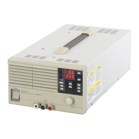
REGULATED DC POWER SUPPLY
PDS20-18/PDS36-10
PDS60-6
SERVICE MANUAL
Front Panel
(PDS20-18 ; A63-0309-03)
(PDS36-10 ; A63-0311-03)
(PDS60-6 ; A63-0315-03)
POWER
REGULATED DC POWER SUPPLY
Circuit Protector
(S79-0625-05)
Rubber Foot
(J02-0506-05)
Handle
(K01-0556-05)
PDS36-10
0
+36V (10A)
-
+
Terminal ; White
Terminal ; Red
(E21-0807-03)
(E21-0806-03)
0
+60V (6A)
GND
Terminal ; White
Terminal ; Red
(E21-0807-03)
(E21-0806-03)
Terminal ; Black
(E21-0808-03)
KENWOOD TMI CORPORATION
© 1998-4/B51-1132-00 (K/K)
Push Button
(K29-7204-04)
OUTPUT
CV
8.8.8.8.
CC
8.8.8.8.
CVP
PRESET
KEYLOCK/LOCAL
VOLTAGE
MEMCRY
CURRENT
FAST/SLOW
(K21-0911-04)
Advertisement
Table of Contents

Related Manuals for Kenwood pds20-18


Summary of Contents for Kenwood pds20-18
- Page 1 REGULATED DC POWER SUPPLY PDS20-18/PDS36-10 KENWOOD TMI CORPORATION PDS60-6 SERVICE MANUAL © 1998-4/B51-1132-00 (K/K) Front Panel (PDS20-18 ; A63-0309-03) (PDS36-10 ; A63-0311-03) Handle Push Button (PDS60-6 ; A63-0315-03) (K01-0556-05) (K29-7204-04) OUTPUT 8.8.8.8. 8.8.8.8. PRESET KEYLOCK/LOCAL VOLTAGE MEMCRY CURRENT FAST/SLOW POWER...
-
Page 2: Table Of Contents
PDS20-18/PDS36-10/PDS60-6 WARNING The following instructions are for use by qualified personnel only. To avoid electric shock, do not perform any servicing other than contained in the operating instructions unless you are qualified to do so. CONTENTS SPECIFICATIONS ......................3 CIRCUIT DESCRIPTION ....................6 BLOCK DIAGRAM ......................11... -
Page 3: Specifications
PDS20-18/PDS36-10/PDS60-6 SPECIFICATIONS Model name PDS20-18 PDS36-10 PDS60-6 Rated output voltage (V) Rated output current (A) Output Output voltage range (V) 0-20 0-36 0-60 Output current range (A) 0-18 0-10 Rated output power (W) Constant voltage characteristics Power regulation 0.005% +1 mV (for... - Page 4 PDS20-18/PDS36-10/PDS60-6 SPECIFICATIONS Model name PDS20-36 PDS36-20 PDS60-12 Output signals In constant voltage operation (option) Open collector, active Low In constant current operation (option) Open collector, active Low Alarm circuit operation Open collector, active Low Output voltage monitor (option) 0 to 10 V, F.S.accuracy: Output current monitor (option) 0 to 10 V, F.S.accuracy:...
- Page 5 PDS20-18/PDS36-10/PDS60-6 SPECIFICATIONS Model name PDS20-36 PDS36-20 PDS60-12 Dielectric strength Chassis to power input 1.5 kVac, 1minute Power input to output terminal 2.3 kVac 1 minute Source voltage 100 to 240 Vac, 50/60 Hz single-phase (this equipment is designed to operate...
-
Page 6: Circuit Description
PDS20-18/PDS36-10/PDS60-6 CIRCUIT DESCRIPTION is output as the current monitor signal (about +2.8 V CONTROL UNIT (X77-2120) at the full scale) by the monitor amplifier IC107-1/2. Digital-to Analog Converter Circuit The OVP signal set on the panel is output as OVP Various signals received from the CPU unit are set voltage monitor signal (about +2.8 V at the... - Page 7 PDS20-18/PDS36-10/PDS60-6 CIRCUIT DESCRIPTION POWER UNIT (X68-1970) Power Control Circuit Input side Switching Model Bleeder current Voltage Current Q12 uses the control signals from the control unit 20-18 About 1 A About 20 V About 3.5 A to control the current of the constant...
- Page 8 PDS20-18/PDS36-10/PDS60-6 CIRCUIT DESCRIPTION CPU UNIT (X77-2110) Strobe signals for controlling the D/A converter circuit IC7 (CPU) runs on 16 MHz clock pulses IC17 generated by the X1 quartz oscillator. Signals for the panel unit display driver (IC1and IC2) are output by IC17.
- Page 9 PDS20-18/PDS36-10/PDS60-6 CIRCUIT DESCRIPTION MOTHER UNIT (X67-1420) Internal 15 V Rectifier and Smoother Th i s c ir c u i t p r o d u ce s r e ct i f i e d a n d sm o o t h e d...
- Page 10 PDS20-18/PDS36-10/PDS60-6 CIRCUIT DESCRIPTION AC UNIT (X68-1980) Line Filter This line filte r fil trate s DC volta ge ha ving passe d Line Filter throug h the seco ndary side recti fier a nd sm oothe r This filter filtrates AC power and feeds filtrated circuit (G) before it is supplied to the power unit.
-
Page 11: Block Diagram
PDS BLOCK DIAGRAM POWER SUPPLY UNIT AC UNIT Shunt V OUT SENSE VCE Detection Sub Power Preset Primary Side Control Circuit CONTROL UNIT Shut Down Circuit CPU UNIT MOTHER UNIT V DISP Set Up I/O Control Switch I DISP I/O Option Board PANEL UNIT... - Page 12 BLOCK DIAGRAM PANEL UNIT (X66-1600-00) Switch LED CPU UNIT (X77-2110-00) D-DRU 7-Segment LED 7-Segment LED Driver IC1,2 Rotary Encoder P_SW Panel Switch Set Up Volume CONTROL UNIT OVP Volume (X77-2120-00)
-
Page 13: Block Diagram
BLOCK DIAGRAM MOTHER UNIT (X67-1420-0X) Control Unit Trip + PH2,D3.4 MAIN SWITCH Control IC1,D7.10 + 15V Main Power Rectifier & Control Smoother D100 Power & Rectifier & Control Unit Smoother Main Power Primary Side MAIN AC Rectifier & D11.12 Smoother Sub-Power Switching Power &... - Page 14 BLOCK DIAGRAM POWER SUPPLY UNIT (X68-1970-0X) Vce Voltage Power Control OUTPUT + (AC UNIT) Q1~10 Primary Input OUTPUT- (AC UNIT) Bleeder Circuit Bleeder Circuit Q14,16,17,19 IC3(1/2) Drive Circuit Control Primary Overvoltage Q11~13 (CONTROL UNIT) Detection IC4(1/2), Q18 MAX CC Error Amp IC4(2/2) CC Monitor (CONTROL UNIT)
- Page 15 BLOCK DIAGRAM AC UNIT (X68-1980-00,02,04) D18.19.20 Primary Side Current Detector Main Power MAIN AC Power Unit Secondary Side Line Main Power Line Rectifier & Filter Q4..7 Primary Side Filter Smoother Rectifier Main Power Switching Over Heart Protector Power Unit IC2,PH2.3 IC100,PH100 IC1,PH1.2.3 Primary Side...
- Page 16 BLOCK DIAGRAM CONTROL UNIT (X77-2120-0X) (CPU) External OUTPUT ON/OFF OUTPUT ON/OFF +5 GND Outpot Port DATA Reference DAC IC12 CLOCK Isolation + Sensing Compalator Mon. DAC Input Port - Sensing IC7,8 IC16 IC14 EEPROM Monitor Amp IC107 M/S Reference CC Status Error Amp IC105 Reference Amp...
- Page 17 BLOCK DIAGRAM CPU UNIT (X77-2110-00) CONTROL UNIT (X77-2120-0x) Rotary Encoder Panel Switch S1~S10 IC20 X66-1600-00 Interruption Input Port Processing IC9,14 IC21,22 IC1,2,4,5,7,13 OUTPUT:LED Latch Circuit IC6,8,12 OUTPUT PORT Switch IC15 Display Drive IC1,2 X77-2110-00 Option Board X72-1380-00 X72-1380-01 X72-1460-00...
-
Page 18: Adjustment
PDS20-18/PDS36-10/PDS60-6 ADJUSTMENT To obtain the best performance, periodically calibrate TEST EQUIPMENT R E Q U I R E D the unit. Sometimes, only one mode need be The following instrument or their equivalent should calibrated, while at other times, all modes should be be used for making adjustment. - Page 19 PDS20-18/PDS36-10/PDS60-6 ADJUSTMENT 1-5. Voltage Monitor Gain Press the VOLTAGE key. (The VOLTAGE LED goes on.) Press the KEYLOCK/LOCAL key. Wait until operation becomes stable (for about ten seconds.) Press the MEMORY key. (The PRESET 1 to PRESET 3 LEDs go on.) Press the KEYLOCK/LOCAL key.
- Page 20 PDS20-18/PDS36-10/PDS60-6 ADJUSTMENT 4. Press the MEMORY key. (The PRESET 1 to PRESET 3 LEDs goon.) 5. Press the PRESET 2key. (The PRESET 1 LED goes on.) 2-4. Current Monitor Offset 1. Press the CURRENT key. (The CURRENT LED goes on.) 2.
- Page 21 Ref. No 20-18 36-10 60-6 Parts No. Ref. No 20-18 36-10 60-6 Name & Description Name & Description N15-1040-41 PLAIN WASHER PDS20-18 (Y86-2680-00) / PDS36-10 (Y86-2700-00) / PDS60-6 (Y86-2730-00) N17-1040-41 TOOTHED LOCK WASHER N32-4010-41 SCREW, FLAT HD A01-4090-02 CASE N33-3006-41...
- Page 22 Teile ohne Parts No. werden nicht geliefert. Parts No. Ref. No 20-18 36-10 60-6 Parts No. Ref. No 20-18 36-10 60-6 Name & Description Name & Description MOTHER UNIT (X67-1420-0X) / PDS20-18(-02), PDS36-10(-00), PDS60-6(-04) PANEL UNIT (X66-1600-00) J30-0659-04 SPACER R12-3546-05 RES. SEMI FIXED 10KB...
- Page 23 * New Parts * New Parts Parts without Parts No. are not supplied. Parts without Parts No. are not supplied. Les articles non mentionnes dans le Parts No. ne sont pas fournis. Les articles non mentionnes dans le Parts No. ne sont pas fournis. Teile ohne Parts No.
- Page 24 C90-4575-05 CAP. ELECTRO 2200u L07-1546-15 POWER TRANSFORMER C90-4576-05 CAP. ELECTRO 1000u C90-4654-05 CAP. ELECTRO 470u 100V POWER SUPPLY UNIT (X68-1970-0X) / PDS20-18(-02), PDS36-10(-00), PDS60-6(-04) C91-2720-05 CAP. FILM 0.22u 630V F29-0537-05 INSULATOR WASHER C91-2720-05 CAP. FILM 0.22u 630V F20-3053-04 INSULATOR SHEET CF92V1H105J CAP.
- Page 25 * New Parts * New Parts Parts without Parts No. are not supplied. Parts without Parts No. are not supplied. Les articles non mentionnes dans le Parts No. ne sont pas fournis. Les articles non mentionnes dans le Parts No. ne sont pas fournis. Teile ohne Parts No.
- Page 26 RES. SEMI FIXED 10KB 1/2W C91-2701-05 CAP. FILM 0.022u 630V S76-0646-05 THERMAL SWITCH C91-2700-05 CAP. FILM 0.1u 630V AC UNIT (X68-1980-0X) / PDS20-18(-02), PDS36-10(-00), PDS60-6(-04) C91-2702-05 CAP. FILM 0.047u 630V C91-2700-05 CAP. FILM 0.1u 630V F01-2358-03 HEAT SINK C91-2702-05 CAP. FILM 0.047u...
- Page 27 * New Parts * New Parts Parts without Parts No. are not supplied. Parts without Parts No. are not supplied. Les articles non mentionnes dans le Parts No. ne sont pas fournis. Les articles non mentionnes dans le Parts No. ne sont pas fournis. Teile ohne Parts No.
- Page 28 * New Parts * New Parts Parts without Parts No. are not supplied. Parts without Parts No. are not supplied. Les articles non mentionnes dans le Parts No. ne sont pas fournis. Les articles non mentionnes dans le Parts No. ne sont pas fournis. Teile ohne Parts No.
- Page 29 * New Parts * New Parts Parts without Parts No. are not supplied. Parts without Parts No. are not supplied. Les articles non mentionnes dans le Parts No. ne sont pas fournis. Les articles non mentionnes dans le Parts No. ne sont pas fournis. Teile ohne Parts No.
- Page 30 RES. CHIP(2x1.25) 1/10W RK73FB2A103J RES. CHIP(2x1.25) 1/10W RK73FB2A103J RES. CHIP(2x1.25) 1/10W L77-2527-05 CRYSTAL RESONATOR RK73FB2A103J RES. CHIP(2x1.25) 1/10W CONTROL UNIT (X77-2120-0X) / PDS20-18(-02), PDS36-10(-00), PDS60-6(-04) RK73FB2A103J RES. CHIP(2x1.25) 1/10W RK73FB2A103J RES. CHIP(2x1.25) 1/10W J73-0524-02 PCB (UNMOUNTED) RK73FB2A103J RES. CHIP(2x1.25) 1/10W RK73FB2A103J RES.
- Page 31 * New Parts * New Parts Parts without Parts No. are not supplied. Parts without Parts No. are not supplied. Les articles non mentionnes dans le Parts No. ne sont pas fournis. Les articles non mentionnes dans le Parts No. ne sont pas fournis. Teile ohne Parts No.
- Page 32 * New Parts * New Parts Parts without Parts No. are not supplied. Parts without Parts No. are not supplied. ¡ ™ Les articles non mentionnes dans le Parts No. ne sont pas fournis. Les articles non mentionnes dans le Parts No. ne sont pas fournis. Teile ohne Parts No.
- Page 33 * New Parts * New Parts Parts without Parts No. are not supplied. Parts without Parts No. are not supplied. £ ¢ Les articles non mentionnes dans le Parts No. ne sont pas fournis. Les articles non mentionnes dans le Parts No. ne sont pas fournis. Teile ohne Parts No.
- Page 34 * New Parts Parts without Parts No. are not supplied. ∞ Les articles non mentionnes dans le Parts No. ne sont pas fournis. Teile ohne Parts No. werden nicht geliefert. Ref. No 20-18 36-10 60-6 Parts No. Name & Description R211 RN73FH2A153D RES.
-
Page 35: Schematic Diagram
PDS SCHEMATIC DIAGRAM Rear panel output ; 36V, 20V Front panel output : only PDS60-6 X68 - 1970 - 00 X68 - 1970 - 02 no used 20V 36V 20V 36V AC UNIT POWER UNIT OPTION BOARD MOTHER UNIT CPU UNIT CONTROL UNIT PANEL UNIT... -
Page 36: Schematic Diagram
SCHEMATIC DIAGRAM PANEL UNIT X66-1600-00 IC1,2 : TB62709F... - Page 37 SCHEMATIC DIAGRAM MOTHER UNIT X67-1420-02: PDS20-18 X67-1420-00: PDS36-10 X67-1420-04: PDS60-6 C105 0.1 u 630V C106 0.1 u 630V 250V 3.2W 470P 250V 470P 250V :TA7815S :TA76431S :2SK2056 :2SC2655(Y) Q100 :2SD2531 Q101 :2SC1815(Y) C109 C110 C111,C112 C113-C116 1500u 35V PDS20-18 6800u 35V...
- Page 38 SCHEMATIC DIAGRAM POWER UNIT X68-1970-02 : PDS20-18 X68-1970-00 : PDS36-10 X68-1970-04 : PDS60- 6 X68-1970-0x : NJM2114D : TA78L005AP IC3, 4 : NJM4558D Q1-10,17 : 2SC5198(O) : 2SA1941(O) Q12, 20 : 2SD1407(O) Q13,14, 18, : 2SC1815(Y) Q15,16 : 2SC1015(Y) : 2SC1815(Y)[PDS20-18]...
- Page 39 SCHEMATIC DIAGRAM AC UNIT X68-1980-02 : PDS20-18 X68-1980-00 : PDS36-10 X68-1980-04 : PDS60-6 250V 250V 220p 2.2u 180K 180K 100K 1/2W 4700P 250V 100K 0.01 u 2.2M 1/4W PH2 b/2 1.5k : FA5331P D1,9,105 : MTZ5.6JB C41,42 C44,45 C46,47 C52,53,55,121-123...
- Page 40 SCHEMATIC DIAGRAM CPU UNIT X77-2110-00 :HD74HC245FP IC2,3,9,10,14 :HD74HC244FP :HD74HC688FP IC5,13 :HD74HC138FP :HD74HC221FP :70325GJ-10-5BG IC8,11 :HD74HC74FP IC12,28 :HD74HC08FP IC15 :W24258S-70LE IC16-19 :HD74HC574FP IC20 :AT29C010A-12J1 IC21,22 :HD74HC05FP IC23 :HD74HC14FP IC24 :HD74HC04FP IC25 :HD74HC86FP IC26 :HD74HC32FP IC27 :MAX809MEUR-T 6.3V...
- Page 41 30K 1/10W 1.6K 1/10W 270K 1/10W R225 R226 R231 R232 R241 R502 TH103 TH108 PDS20-18 15K 1/10W 43K 1/10W 33K 1/10W 1.8K 1/10W 1.5K 1/10W 1.0K 1/10W used used PDS36-10 62K 1/10W 91K 1/10W – – 1.0K 1/10W – used 1.0K 1/10W...
-
Page 42: P.c. Board
PC BOARD (Component side view) PANEL UNIT (X66-1600-00) GREEN X66-1600-00/A J73-0520-23/A Refer to the schematic diagram for the values of resistors and capacitors. - Page 43 PC BOARD (Component side view) MOTHER UNIT (X67-1420-0X) Refer to the schematic diagram for the values of resistors and capacitors.
- Page 44 PC BOARD (Component side view) POWER SUPPLY UNIT (X68-1970-0X) A/3 Refer to the schematic diagram for the values of resistors and capacitors.
- Page 45 PC BOARD (Component side view) AC UNIT (X68-1980-0X) Refer to the schematic diagram for the values of resistors and capacitors.
- Page 46 PC BOARD (Component side view) CPU UNIT (X77-2110-00) Refer to the schematic diagram for the values of resistors and capacitors.
- Page 47 PC BOARD (Component side view) CONTROL UNIT (X77-2120-0X) Refer to the schematic diagram for the values of resistors and capacitors.
- Page 48 PDS20-18/PDS36-10/PDS60-6 A product of KENWOOD TMI CORPORATION 1-16-2, HAKUSAN, MIDORI-KU, YOKOHAMA CITY 226, JAPAN...