Advertisement
Table of Contents
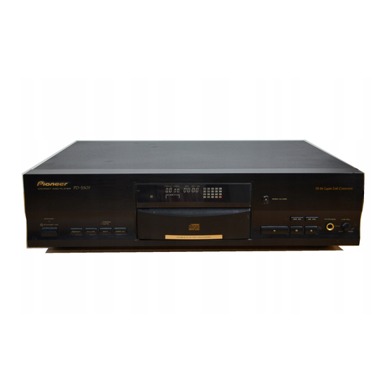
COMPACT DISC PLAYER
PD-S507
THIS MANUAL IS APPLICABLE TO THE FOLLOWING MODEL ( S ) AND TYPE ( S ) .
Model
Type
PD-S507
‡
MYXK
‡
MVXK
CONTENTS
1. SAFETY INFORMATION .................................... 2
2. EXPLODED VIEWS AND PARTS LIST ............. 3
3. SCHEMATIC DIAGRAM ................................... 10
4. PCB CONNECTION DIAGRAM ....................... 17
5. PCB PARTS LIST ............................................. 24
6. ADJUSTMENT .................................................. 27
PIONEER ELECTRONIC CORPORATION
PIONEER ELECTRONICS SERVICE, INC. P.O. Box 1760, Long Beach, CA 90801-1760, U.S.A.
PIONEER ELECTRONIC (EUROPE) N.V. Haven 1087, Keetberglaan 1, 9120 Melsele, Belgium
PIONEER ELECTRONICS ASIACENTRE PTE. LTD. 501 Orchard Road, #10-00 Wheelock Place, Singapore 238880
PIONEER ELECTRONIC CORPORATION 1998
Power Requirement
AC220-230V
AC220-230V
4-1, Meguro 1-Chome, Meguro-ku, Tokyo 153-8654, Japan
7. GENERAL INFORMATION .............................. 35
7.1 IC ................................................................ 35
7.2 DISPLAY .................................................... 36
7.3 BLOCK DIAGRAM ..................................... 37
................................................................... 38
T-ZZR OCT. 1998 Printed in Japan
ORDER NO.
RRV2034
Remarks
Advertisement
Table of Contents

Related Manuals for Pioneer PD-S507


Summary of Contents for Pioneer PD-S507
-
Page 1: Table Of Contents
PIONEER ELECTRONICS SERVICE, INC. P.O. Box 1760, Long Beach, CA 90801-1760, U.S.A. PIONEER ELECTRONIC (EUROPE) N.V. Haven 1087, Keetberglaan 1, 9120 Melsele, Belgium PIONEER ELECTRONICS ASIACENTRE PTE. LTD. 501 Orchard Road, #10-00 Wheelock Place, Singapore 238880 PIONEER ELECTRONIC CORPORATION 1998... -
Page 2: Safety Information
If you are not qualified to perform the repair of this product properly and safely, you should not risk trying to do so and refer the repair to a qualified service technician. IMPORTANT THIS PIONEER APPARATUS CONTAINS LASER OF CLASS 1. SERVICING OPERATION OF THE APPARATUS S H O U L D B E D O N E B Y A S P E C I A L L Y INSTRUCTED PERSON. -
Page 3: Exploded Views And Parts List
See Contrast table (2) Polyethylene Bag See Contrast table (2) (115 × 270 × 0.05) Warranty Card ARY7022 (2) CONTRAST TABLE PD-S507/MYXK and MVXK are constructed the same except for the following: Part No. Mark Symbol and Description Remarks MYXK type MVXK type... - Page 4 PD-S507 2.2 EXTERIOR For MVXK type Fuse Holder Refer to "2.4 LOADING MECHANISM ASSY T 96". : MVXK type Only Removal of the Tray Panel Refer to "2.3 FRONT PANEL SECTION".
- Page 5 Disc Guard REC1305 Loading Mechanism Assy T96 PXA1604 Caution Label HE See Contrast table (2) (2) CONTRAST TABLE PD-S507/MYXK and MVXK are constructed the same except for the following: Part No. Mark Symbol and Description Remarks MYXK type MVXK type...
-
Page 6: Front Panel Section
PD-S507 2.3 FRONT PANEL SECTION FRONT PANEL SECTION PARTS LIST Mark No. Description Part No. Mark No. Description Part No. SWITCH BOARD ASSY PWZ3766 LED Lens PNW2019 MODE BOARD ASSY PWZ3768 Function Panel PNW2807 HEADPHONE BOARD ASSY PWZ3773 PLAY Button B... - Page 7 PD-S507 2.4 LOADING MECHANISM ASSY T96 Refer to " 2.5 SERVO MECHANISM ASSY T96". Spacer...
- Page 8 PD-S507 LOADING MECHANISM ASSY T96 PARTS LIST Mark No. Description Parts No. Mark No. Description Parts No. Lever Switch (S601) DSK1003 Turn Table PNR1044 Float Screw PBA1027 Servo Mechanism Assy T96 PXA1606 Rubber Belt PEB1186 E Ring YE20FUC Motor Pulley...
- Page 9 PD-S507 2.5 SERVO MECHANISM ASSY T96 SERVO MECHANISM ASSY T96 PARTS LIST Mark No. Description Parts No. Carriage D.C. Motor (0.3W) PXM1027 Pinion Gear PNW2055 Spindle Motor Assy PEA1236 (SPINDLE, with Oil) Carriage Base PNW2699 Disc Table PNW1067 Screw JFZ20P030FNI...
-
Page 10: Schematic Diagram
PD-S507 3. SCHEMATIC DIAGRAM Note: When ordering service parts, be sure to refer to "EXPLODED VIEWS AND PARTS LIST" or "PCB PARTS LIST". 3.1 OVERALL SCHEMATIC DIAGRAM CN201 LOADING MECHANISM ASSY T 96 (PXA1604) CN11 KPD7 PICK UP ASSY PEA1335... - Page 11 POWER BOARD AC220-230V 50/60Hz PDG1055: MVXK ASSY (PWZ3770: MYXK/MVXK) AC220-230V 50Hz Power Transformer (PTT1236: MYXK/MVXK) PHONE BOARD ASSY (PWZ3773:MYXK /MVXK) J501 D20PDY0406B PD-S507/MVXK Only V+5D COAXIAL OUTPUT DOUT ASSY (PWZ3775: /MVXK) Only CN701 HLEM26R-1 SWITCH BOARD ASSY (PWZ3766:MYXK/MVXK) CN751 52151-0410...
- Page 12 PD-S507 3.2 MAIN BOARD ASSY, PHONE BOARD ASSY and COAXIAL OUTPUT ASSY MAIN BOARD ASSY (PWZ3762: MYXK) (PWZ3763: MVXK) 220/25 (PCH1128) 1000/16 (PCH1122) 4.7/50 (PCH1127) MA 0.15 4.7/50 (PCH1127)
- Page 13 PD-S507 MVXK ONLY COAXIAL OUTPUT ASSY (PWZ3775) MYXK MVXK 47/50 (PCH1124) 150 µH 1000/16 (PCH1122) 47/50 (PCH1124) 100/50 (PCH1126) 220/25 (PCH1128) PHONE BOARD ASSY (PWZ3773) SIGNAL ROUTE : AUDIO SIGNAL ROUTE 4.7/50 (PCH1127) CAUTION: FOR CONTINUED PROTECTION AGAINST RISK OF FIRE.
- Page 14 PD-S507 3.3 POWER BOARD ASSY, SWITCH BOARD ASSY and MODE BOARD ASSY SWITCH BOARD ASSY MODE BOARD ASSY (PWZ3766) (PWZ3768) SWITCHES S751: REPEAT S752: TIME S753: EDIT S754: DISPLAY S755: STANDBY SWITCHES S701: 7 S702: S703: 3 S704: OPEN/CLOSE S710: 4 1 S711: ¡...
- Page 15 PD-S507 CN351...
- Page 16 PD-S507 MAIN BOARD ASSY Waveforms ∗1 50T-JUMP: After switching to the pause mode, press the manual search key. Note: The encircled numbers denote measuring point in the schematic diagram. ∗2 FOCUS-IN: Press the play key without loading a disc. IC301- Pin 3 :...
-
Page 17: Pcb Connection Diagram
PD-S507 4. PCB CONNECTION DIAGRAM NOTE FOR PCB DIAGRAMS: 1. Part numbers in PCB diagrams match those in the schematic diagrams. 2. A comparison between the main parts of PCB and schematic Symbol in PCB Symbol in Schematic diagrams is shown below. - Page 18 SIDE A MAIN BOARD ASSY Q391 IC406 Q403 Q404 IC20 IC341 IC405 IC33 IC34 COAXIAL OUTPUT ASSY Q151 VR153 VR154 IC202 VR155 VR151 VR152 (PD-S507/MVXK Only) VR156 To Pickup Assy IC201 CN610 To Loading Motor and S601 J501 CN701 (PNP1448–C)
- Page 19 PD-S507 SIDE B MAIN BOARD ASSY IC341 Q452 Q451 Q405 IC302 IC401 IC301 Q152 IC151 (PNP1448–C)
- Page 20 PD-S507 4.3 POWER BOARD ASSY SIDE A NEUTRAL POWER BOARD ASSY LIVE AC POWER CORD CN11 (PNP1448-C)
- Page 21 PD-S507 SIDE B POWER BOARD ASSY (PNP1448-C)
- Page 22 PD-S507 SIDE A 4.4 SWITCH BOARD ASSY and MODE BOARD ASSY SWITCH BOARD ASSY MODE BOARD ASSY IC702 IC701 CN351 (PNP1448-C)
- Page 23 PD-S507 SIDE B SWITCH BOARD ASSY MODE BOARD ASSY IC701 IC703 (PNP1448-C)
-
Page 24: Pcb Parts List
PD-S507 5. PCB PARTS LIST NOTES : ÷ Parts marked by “ NSP ” are generally unavailable because they are not in our Master Spare Parts List. ÷ The mark found on some component parts indicates the importance of the safety factor of the part. -
Page 25: Main Board Assy
PD-S507 PARTS LIST FOR PD-S507/MVXK Mark No. Description Part No. Mark No. Description Part No. MOTHER BOARD ASSY C152, C307 CKSQYB473K50 C151 CKSQYB682K50 OTHERS C157 CKSQYB823K25 PC Board (MOTHER) PNP1448 C172, C185, C205, C210, C215 CKSQYF103Z50 C219, C24, C305, C316, C325... - Page 26 PD-S507 Mark No. Description Part No. Mark No. Description Part No. COILS AND FILTERS RESISTORS L1110 (FERRITE BEADS) PTH1014 All Resistors RS1/10S&&&J L1108 (FERRITE BEADS) PTH1016 OTHERS CAPACITORS 4P CABLE HOLDER 51048-0400 CEGA4R7M50 J751 4P JUMPER WIRE D20PDY0410E C18, C19...
-
Page 27: Adjustment
PD-S507 6. ADJUSTMENT 6.1 PREPARATIONS 6.1.1 Jigs and Measuring Instruments 39 kΩ 0.001µF CD TEST DISC Low pass filter 1 screwdriver screwdriver screwdriver (YEDS-7) (small) (medium) (large) (39 kΩ + 0.001µF) 56 kΩ 0.001µF Dual-trace Precise Ball point hexagon wrench... - Page 28 PD-S507 6.2 ADJUSTMENT 6.2.1 How to Start/Cancel Test Mode TEST MODE : ON TEST MODE TEST MODE W384 W384 W385 W385 Short point Short point MAIN BOARD ASSY MAIN BOARD ASSY TEST MODE : PLAY TEST DISC: YEDS-7 ¡ EDIT...
- Page 29 PD-S507 6.2.3 Check and Adjustment 1. Focus Offset Adjustment Test mode DC voltage VR154 0±50mV None disc MAIN BOARD ASSY Oscilloscope DC Mode V: 5mV/div H: 10mSec/div Player START (CN201) Prove (10:1) MAIN BOARD ASSY 2. Grating Adjustment Turn counterclockwise from null.
- Page 30 PD-S507 3. Tracking Error Barance Adjustment Test mode SPDL servo CLOSE FOCUS servo CLOSE TRKG servo OPEN Innermost TEST DISC circumference VR155 (1 TRK) PLAY MAIN BOARD ASSY Oscilloscope DC Mode V: 10mV/div Player START H: 5mSec/div Low pass filter 1...
- Page 31 PD-S507 5. RF Level Adjustment Test mode SPDL servo CLOSE FOCUS servo CLOSE 1.2VP-P TRKG servo CLOSE ±0.1V Innermost TEST DISC circumference VR153 (1 TRK) PLAY MAIN BOARD ASSY Oscilloscope AC Mode V: 50mV/div H: 10mSec/div Player START (CN201) Prove (10:1) MAIN BOARD ASSY 6.
- Page 32 PD-S507 7. RF Level Adjustment Check Test mode CLOSE SPDL servo FOCUS servo CLOSE TRKG servo CLOSE 1.2VP-P ±0.1V Innermost TEST DISC circumference VR153 (1 TRK) PLAY MAIN BOARD ASSY Make adjustment if the value exceeds the specified range. Oscilloscope...
- Page 33 PD-S507 9. Focus Best Adjustment Test mode SPDL servo CLOSE FOCUS servo CLOSE TRKG servo CLOSE Innermost TEST DISC circumference VR156 (1 TRK) Adjust the RF level to maximum, with PLAY MAIN BOARD ASSY the focus error voltage within ±150mV.
- Page 34 PD-S507 11. Focus Best Adjustment Adjust this point only if adjustment was made in item 10. Test mode SPDL servo CLOSE FOCUS servo CLOSE TRKG servo CLOSE Innermost TEST DISC circumference VR156 (1 TRK) Adjust the RF level to maximum, with PLAY the focus error voltage within ±150mV.
-
Page 35: General Information
PD-S507 7. GENERAL INFORMATION 7.1 IC ¶ The information shown in the list is basic information and may not 7 PE8001A (IC401: MAIN BOARD ASSY) correspond exactly to that shown in the schematic diagrams. 7 D/A CONVERTER IC ¶ Pin Arrangement ¶... -
Page 36: Display
PD-S507 7.2 DISPLAY 7 PEL1085 (V701: SWITCH BOARD ASSY) 7 FL INDICATOR TUBE ¶ Pin Assignment ¶ Pin Connection ¶ Grid Assignment ¶ Anode Connection... -
Page 37: Block Diagram
PD-S507 7.3 BLOCK DIAGRAM •... -
Page 38: Panel Facilities And Specifications
PD-S507 8. PANEL FACILITIES AND SPECIFICATIONS 7 PANEL FACILITIES PD-S507 FRONT PANEL FRONT PANEL STANDBY/ON switch and STANDBY indicator 2 REPEAT button 3 HI-LITE button 4 COMPU/AUTO EDIT button (• COMPU/•• AUTO) 5 DISPLAY button 6 Remote sensor Receives the signal from the remote control unit. -
Page 39: Specifications
PD-S507 7 SPECIFICATIONS 1. General Type ......... Compact disc digital audio system Power requirements ........ AC 220 - 230 V, 50/60 Hz Power consumption ..............13 W Power consumption in standby mode ........3 W Operating temperature ..........+5˚C - +35˚C Weight ...................