Table of Contents
Advertisement
Advertisement
Table of Contents

Related Manuals for Honeywell r7284


Summary of Contents for Honeywell r7284
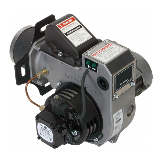
- Page 1 KNA-S Patent No. D665, 901 Oil Fired Burner KNA-M / L ® 9.801-300.0 rev. 8/13...
-
Page 3: Table Of Contents
Trained Service Technician's Regular Maintenance 17 Removing Nozzle Line for Service Nozzle Installation Nozzle Replacement 18-19 Check/Adjust Electrodes Blower Wheel Replacement ......19 Honeywell R7284U Electronic Oil Primary ...20-23 Replacement Parts ........24-27 Warranty ............28 KNA Burner Manual 9.801-300.0 rev. 8/13... -
Page 4: General Information
Section: General Information General Information Owner’s Responsibility WARNING Hazard Definitions Incorrect Installation, adjust- ment and use of this burner could result in severe personal Indicates a hazardous situation DANGER injury, death, or substantial which, if not avoided, will result property damage from fire, car- in serious injury of death. -
Page 5: Special Requirements
Section: General Information Special Requirements General Specification NOTICE TABLE 1: BURNER SPECIFICATIONS • The installation of a burner shall be in ac- Capacity Firing rate - 0.75-3.00 GPH "S" Models cordance with the regulation of authorities (Note 1) 1.00-7.00 GPH "M/L" Models having jurisdiction. -
Page 6: Inspect/Prepare Installation Site
Section: Inspect/Prepare Installation Site Inspect/Prepare Inspect Flue Pipe Equipment Site Location Fire, Smoke & WARNING Asphyxiation Hazard Professional Service DANGER • Carefully inspect the exhaust vent system Required • Make sure it is properly sized and in good working Incorrect installation, adjust- condition ment and use of this burner could result in severe personal... -
Page 7: Combustion Air Supply Information
Section: Inspect/Prepare Installation Site Schedule Maintenance Program Minimum Chamber Dimensions Verify that the equipment combustion chamber pro- The new design of flame retention oil burners is more vides at least the minimum dimensions given in Table 2. efficient. One result of increased efficiency, is lower flue gas temperatures. -
Page 8: Prepare The Burner
Section: Prepare the Burner Prepare the Burner Mount Burner on Equipment Verify that the air tube installed on the burner provides General the correct insertion depth. Refer to Figure 3. In most cases, the burner is ready to mount to the The end of the air tube should normally be 1/4"... -
Page 9: Connect Fuel Lines
Section: Prepare the Burner Connect Fuel Lines Fuel Line Valves and Filter Do Not Install By-pass WARNING WARNING Oil Leak and Fire Hazard Plug with 1-Pipe System Install the oil tank following applicable standards Failure to comply could cause immediate pump in the U.S. -
Page 10: Wiring The Burner
Section: Wiring the Burner Wiring the Burner Fuel Supply Below The Level Of The Burner When the fuel supply is below the level of the burner, a two-pipe supply system is required. Consult the fuel Electrical Shock Hazard DANGER pump manufacturer's specifications for lift and vacuum capability. -
Page 11: Wiring Connectiom Diagrams
Section: Wiring the Burner Wiring Connections Diagram Explosion, Fire, Scald and WARNING Burn Hazard All heating equipment must have HIGH LIMIT protection to interrupt electrical power and shutdown the burner if operat- ing or safety controls fail and cause a runaway condition. •... - Page 12 Section: Wiring the Burner Wiring Connection Diagrams FIGURE 7b - 115V WIRING DIAGRAM WITH 24V SOLENOID COIL IGN. LIGHT THERMOSTAT FUEL SOLENOID P1 1 FUEL T-STAT IGNITOR 115V LINE 2 POWER LIGHT 115V MOTOR LINE 1 115V 98013000-2 FIGURE 7c - 230V WIRING DIAGRAM WITH 230V SOLENOID COIL IGN.
- Page 13 IGNITOR POWER LIGHT MOTOR LINE 1 98013000-6 FIGURE 7g- 115V WIRING DIAGRAM WITH PRIMARY CONTROL 9.807-551.0 PRIMARY IGN. LIGHT CELL CONTROL 115V HONEYWELL R7184U FUEL THERMOSTAT SOLENOID 115V IGNITOR FUEL 115V MOTOR LINE 2 115V LINE 1 POWER LIGHT 115V...
-
Page 14: Start The Burner And Set Combustion
Section: Start the Burner and Set Combustion FIGURE 7h - 230V MOTOR WIRING DIAGRAM WITH 115V PRIMARY CONTROL 9.807-552.0 PRIMARY IGN. LIGHT CELL CONTROL 115V HONEYWELL R7184U FUEL THERMOSTAT SOLENOID 115V IGNITOR FUEL 115V MOTOR LINE 2 230V 115V LINE 1... -
Page 15: Burner Tube, Static Disk, Air Cone, Set-Up
Section: Start the Burner and Set Combustion TABLE 3a KNA BURNER WITH 1.0" AIR TUBE LENGTH KNA Air Tube, Air Cone & Static Disk Combinations Air Tube Length Air Cone GPH Rating .75 - 1.25 1.25 - 1.75 1.75 - 2.00 2.00 - 2.25 2.25 - 2.75 2.75 - 3.50... -
Page 16: Set Combustion With Test Instruments
Section: Start the Burner and Set Combustion Oil Burning Equipment shall be CAUTION connected to flues having suf- ficient draft at all times to ensure safe and proper operation of burner. Set Combustion with Test Instruments 1. Allow the burner to run for approximately 5 to 10 minutes. -
Page 17: Perform Regular Maintenance
Section: Perform Regular Maintenance Perform Regular Maintenance The following guidelines are provided for routine maintenance. It is good practice to keep a record of Regular Maintenance to be performed by trained the service performed and the combustion test results. service technicians q Replace the oil supply line filter. -
Page 18: Removing Nozzle Line For Service
Section: Perform Regular Maintenance Removing the Nozzle for Service Nozzle Installation (Reference the Replacement Parts Diagram) Perform the following steps when replacing a nozzle. Correct Nozzle and Flow Protect Nozzle from Damage CAUTION WARNING Rate Required A damaged nozzle could cause impaired combustion, sooting, puffback of hot Incorrect nozzles and flow gases, smoke, oil leakage and potential fire or... -
Page 19: Check/Adjust Electrodes
Section: Perform Regular Maintenance FIGURE 9. - GUN ASSEMBLY/STATIC DISK/AIR TUBE Electrode Assembly Electrode Extension Rods Air Cone Fuel Nozzle Fuel Line Connector 37° Flare Gun Holder Air Tube Assembly Check / Adjust Electrodes 4. Use a 5/8" open-end wrench to carefully remove the existing nozzle. -
Page 20: Honeywell R7284U Electronic Oil Primary
Valve: 120 Vac, 1A released. Igniter: 120 Vac, 3A Lockout Modes Low Voltage Shutdown: 80 Vac The R7284 has three types of lockout modes that are Environmental Ratings: entered when an error is encountered. Operating/Shipping Temperature: -40°F to Disable Function +150°F (-40°C to +66°C). - Page 21 RUNNING 255 OHMS Fig. 12. R7284 terminals, connectors, LED, reset button If at any point there is an event generating a lockout, one of the following screens will be displayed. Control is in Soft Lockout. Control...
- Page 22 R7284 Flame Strength (Basic Interface) From the home screen, press the up button to dis- play most recent error. During normal operation and when the R7284 is in the running state, the LED will show CAD cell resis- ERROR 1...
- Page 23 Section: Honeywell Electronic Oil Primary R7284 Error Codes (Basic Interface) Table 7. Error Codes No. of 1/4 sec Flashes Error Codes No Ignition / Late ignition Max flame losses / CAD Cell high while running Flame out of sequence Low Voltage / EnviraCOM ™...
-
Page 24: Replacement Parts
Section: Replacement Parts Replacement Parts KNA Burner "S" For best performance specify genuine KNA replacement parts Models 8.918-901.0 8.918-902.0 8.918-903.0 8.918-904.0 8.918-905.0 8.918-906.0 8.918-907.0 8.918-908.0 8.918-909.0 8.918-910.0 8.918-911.0 8.918-912.0 8.918-913.0 8.918-914.0 8.918-915.0 8.918-916.0 8.918-917.0 8.918-918.0 8.918-919.0 8.918-920.0 8.920-547.0 KNA Burner Manual 9.801-300.0 rev. 8/13... - Page 25 Section: Replacement Parts Replacement Parts KNA Burner "S" For best performance specify genuine KNA replacement parts KNA Burner Manual 9.801-300.0 rev. 8/13...
- Page 26 Section: Replacement Parts Replacement Parts KNA Burner "M/L" For best performance specify genuine KNA replacement parts Models 8.920-645.0 8.920-646.0 8.920-647.0 8.920-648.0 8.920-649.0 8.920-650.0 8.920-651.0 8.920-960.0 8.920-961.0 8.920-962.0 KNA Burner Manual 9.801-300.0 rev. 8/13...
- Page 27 Section: Replacement Parts Replacement Parts KNA Burner "M/L" For best performance specify genuine KNA replacement parts KNA Burner Manual 9.801-300.0 rev. 8/13...
-
Page 28: Warranty
Section: Waranty Information Limited Warranty Information The Karcher North America (KNA) corporation warrants to persons who purchase its "Products" from KNA for resale, or for incorporation in products for resale ("Customer") that its product is free from defects in material and workmanship for a period of 1 year from date of purchase. To qualify for warranty benefits, products must be installed by a qualified service technician in full compliance with all codes and authorities having jurisdiction and used within the tolerances of KNA defined product specifications. - Page 30 USA: 4275 NW Pacific Rim Blvd - Camas, WA 98607 Phone: 800-833-1600 FAX: 800-833-9200 Printed in USA • Revised 11/12...