Yamaha STAGEPAS 600i Service Manual
Hide thumbs
Also See for STAGEPAS 600i:
- Brochure & specs (8 pages) ,
- Owner's manual (2 pages) ,
- Owner's manual (2 pages)
Table of Contents
Advertisement
Quick Links
012071
PA
20121222-オープンプライス
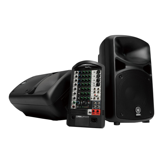
PORTABLE PA SYSTEM
SPEAKER
SERVICE MANUAL
MIXER
CONTENTS (目次)
Specifications (総合仕様) .................................. 3/4
Panel Layout (パネルレイアウト) ............................ 5
Circuit Board Layout (ユニッ トレイアウト) ......... 6
Dimensions (寸法図) ............................................... 7
Disassembly Procedure (分解手順) .................. 8
LSI PIN DESCRIPTION (LSI 端子機能表) ................. 22
Circuit Boards (シート基板図) ............................ 25
TEST PROGRAM (テスト プログラム) ......................... 34
INSPECTIONS (検査) ................................................ 52
UPDATING (アップデート) .......................................... 61
START-UP SEQUENCE (起動シーケンス) ............ 63/65
ENDING SEQUENCE (終了シーケンス) ................ 67/69
HOW TO USE EXT JIG CIRCUIT BOARD
(EXT JIG シートの使用法) ......................................... 71
BLOCK DIAGRAM (ブロックダイアグラム)
LEVEL DIAGRAM (レベルダイアグラム)
Circuit Diagram (回路図)
Copyright (c) Yamaha Corporation. All rights reserved. PDF
SPEAKER
HAMAMATSU, JAPAN
'13.02
Advertisement
Table of Contents

Related Manuals for Yamaha STAGEPAS 600i


Summary of Contents for Yamaha STAGEPAS 600i
- Page 1 ENDING SEQUENCE (終了シーケンス) ....67/69 HOW TO USE EXT JIG CIRCUIT BOARD (EXT JIG シートの使用法) ......... 71 PARTS LIST BLOCK DIAGRAM (ブロックダイアグラム) LEVEL DIAGRAM (レベルダイアグラム) CIRCUIT DIAGRAM (回路図) 012071 20121222-オープンプライス HAMAMATSU, JAPAN Copyright (c) Yamaha Corporation. All rights reserved. PDF ’13.02...
- Page 2 IMPORTANT NOTICE This manual has been provided for the use of authorized Yamaha Retailers and their service personnel. It has been assumed that basic service procedures inherent to the industry, and more specifically Yamaha Products, are already known and understood by the users, and have therefore not been restated.
-
Page 3: Specifications
25.4 kg (56 lbs) (Speaker 10.8 kg x 2 + Mixer 3.8 kg) Crossover Frequency Package Contents 2.8 kHz STAGEPAS 600i (includes two MODEL 600S Speakers and a Powered Mixer), Cover Panel, Power Cord (2m), two Speaker Frequency Range Cables (6m), 12 Non-Skid Pads, Owner’s Manual... - Page 4 STAGEPAS 600i 総合仕様 一般仕様 最大出力(SPEAKERS L/R) 消費電力 340 W + 340 W/4 Ω @ダイナミック at 1 kHz 35 W (Idle)、 100 W (1/8出力) 280 W + 280 W/4 Ω @10 % THD at 1 kHz 入力チャンネルイコライザー特性 ≧230 W + 230 W/4 Ω @1 % THD at 1 kHz 最大可変幅(±15 dB)
-
Page 5: Panel Layout (パネルレイアウト
STAGEPAS 600i PANEL LAYOUT(パネルレイアウト) • Mixer panel (ミキサーパネル) q Mic/Line input jacks (channels 1-4) q マイク / ライン入力端子(チャンネル 1 ∼ 4) w [MIC/LINE] switches (channels 1-4) w [MIC/LINE] スイッチ(チャンネル 1 ∼ 4) e [Hi-Z] switch (channel 4) e [Hi-Z] スイッチ(チャンネル 4)... -
Page 6: Circuit Board Layout (ユニッ トレイアウト
STAGEPAS 600i CIRCUIT BOARD LAYOUT(ユニットレイアウト) ● MIXER 600 ASSEMBLY (ミキサー600組立) DC FAN (DC ファン) AMPS SUB63 SUB61 SUB62 MIX62 MIX61... -
Page 7: Dimensions (寸法図
STAGEPAS 600i ● SP 6 OVERALL ASSEMBLY (SP6総組立) <Front view (正面)> <Right side view (右側面)> <Rear view (背面)> LOUD SPEAKER (TWEETER) (スピーカ (ツイーター) ) NET61 NET62 LOUD SPEAKER (WOOFER) (スピーカ (ウーファー) ) DIMENSIONS(寸法図) ● SP 6 OVERALL ASSEMBLY (SP6総組立) ● MIXER 600 ASSEMBLY (ミキサー600組立)... -
Page 8: Disassembly Procedure (分解手順
STAGEPAS 600i DISASSEMBLY PROCEDURE(分解手順) A. Disassembly of STAGEPAS 600i A. STAGEPAS 600i の分解 ※ インシュロックタイなどを外したときは必ず外す前と When you remove binding ties and such, always 同じように取付けてください。 install as before removal. A-1. Grille 6 Assembly A-1. グリル 6 組立 (Time required: About 1 minute) (所要時間... - Page 9 STAGEPAS 600i • Front view(前面) • Rear view(背面) NWINOUT6 CONNECTOR ASSEMBLY (RED +) (NWINOUT束線6 (赤 +) ) [340] NWINOUT6 CONNECTOR [340] ASSEMBLY (BLACK -) (NWINOUT束線6 (黒 −) ) [340] [340] : PRIORITY SCREW (優先ネジ) LOUD SPEAKER (スピーカ) LOUD SPEAKER (スピーカ)...
- Page 10 STAGEPAS 600i [370] NET62 NET62 HFSPOUT CONNECTOR ASSEMBLY (YELLOW/BLUE) (HFSPOUT束線 (黄/青) ) BAFFLE 6 ASSEMBLY (バッ フル6組立) [320] Fig. A-5 ( 図A-5) A-4. Speaker (Tweeter) A-4. スピーカ(ツイーター) (Time required: About 7 minutes) (所要時間:約 7 分) A-4-1 Remove the grille 6 assembly. (See procedure A-1.) A-4-1 グリル...
- Page 11 STAGEPAS 600i • Rear view(背面) “+” MARKING [60] LOUD SPEAKER (スピーカ) ( “+” マーク) (TWEETER) TW PLATE RED MARKING (TWプレート) (赤色マーク) HFSPOUT CONNECTOR ASSEMBLY (BLUE) (HFSPOUT束線 (青) ) : PRIORITY SCREW HFSPOUT CONNECTOR BAFFLE 6 ASSEMBLY ASSEMBLY (YELLOW) (優先ネジ) (バッ フル6組立)...
- Page 12 STAGEPAS 600i CABINET 6 ASSEMBLY (キャビネッ ト6組立) Plastic nut (プラスチックナッ ト) NET61 [130] [160] NET62 Fig. A-8 ( 図A-8) NET61 [130] [130] NET62 : PRIORITY SCREW (優先ネジ) CABINET 6 ASSEMBLY (キャビネッ ト6組立) [160] Fig. A-9 ( 図A-9)...
- Page 13 STAGEPAS 600i A-7. A-7. ミキサー 600 組立、ACCS 蓋 6 組立の外し方 Mixer 600 Assembly, ACCS Lid 6 Assembly (Time required: About 1 minute) (所要時間:約 1 分) A-7-1 Mixer 600 Assembly A-7-1 ミキサー 600 組立 A-7-1-1 Slide the slide knob in the direction of the arrow in the A-7-1-1 ノブスライドを図の矢印の方向へずらしながら手...
- Page 14 STAGEPAS 600i B. Disassembly of mixer 600 assembly B. ミキサー 600 組立の分解 Before disassembly, remove the mixer 600 assembly or ※ 分解の前に、あらかじめミキサー 600 組立または ACCS lid 6 assembly in advance. (See procedure A-7.) ACCS 蓋 6 組立を外しておきます。 (A-7 項参照) When you remove binding ties and such, always install ※...
- Page 15 STAGEPAS 600i (Time required: About 5 minutes) B-3. DSP Circuit Board B-3. DSP シート (所要時間 : 約 5 分) B-3-1 Remove the bottom cover 6 assembly. B-3-1 下カバー 6 組立を外します。 (B-1 項参照) (See procedure B-1.) B-3-2 シールド MIX6 組立を外します。 (B-2 項参照)...
- Page 16 STAGEPAS 600i [210] BINDING TIE A (インシュロックタイA) [380] ANGLE FAN 6 (FAN金具6) DC FAN [360] (DCファン) TOP COVER 6 (トップカバー6塗装品) : PRIORITY SCREW (優先ネジ) Fig. B-4 ( 図B-4) Fig. B-5 ( 図B-5) B-6. SUB61 Circuit Board, SUB62 Circuit Board B-6.
- Page 17 STAGEPAS 600i INLET ANGLE * Raise the inlet angle claws (インレッ ト金具) SUB61 to be straight in the directions [70] SUB61 of the arrows. (※インレッ ト金具のツメを 矢印の方向にまっすぐに ACIN SHIELD 6 なるように起こして くだ (ACINシールド6) さい。 ) CUSHION A (クッションA) Crow (ツメ) (INLET ANGLE (インレッ...
- Page 18 STAGEPAS 600i B-7. SUB63 Circuit Board (Time required: About 7 minutes) B-7. SUB63 シート (所要時間 : 約 7 分) B-7-1 Remove the bottom cover 6 assembly. B-7-1 下カバー 6 組立を外します。 (B-1 項参照) (See procedure B-1.) B-7-2 シールド MIX6 組立を外します。 (B-2 項参照)...
- Page 19 STAGEPAS 600i [310] AMPS [300] INSULATION SHEET PS 6 (絶縁シートPS6) HEATSINK AMPS6 ASSEMBLY (HS AMPS6組立) PNL SHIELD 6 ASSEMBLY (PNLシールド6組立) MIXER PANEL 6 ASSEMBLY : PRIORITY SCREW (MIXパネル6組立) (優先ネジ) Fig.B-8 ( 図B-8) B-9. MIX61 Circuit Board, MIX62 Circuit Board B-9.
- Page 20 STAGEPAS 600i B-9-6 MIX61 Circuit Board B-9-6 MIX61 シート B-9-6-1 Remove the four (4) screws marked [160], nine (9) B-9-6-1 [160] のネジ 4 本と [540] のネジ 9 本と [A] のナッ screws marked [540], ten (10) nuts marked [A] and ten ト...
- Page 21 STAGEPAS 600i B-9-7-3 Lift the shield mix 6 assembly in the direction of the B-9-7-3 シールド MIX6 組立を写真 B-1 のように矢印の方 arrow as shown in Photo B-1, and remove the fi ve (5) 向へめくり、 [130] のネジ 5 本と [140] の 6 角スペー...
-
Page 22: Lsi Pin Description (Lsi 端子機能表
STAGEPAS 600i LSI PIN DESCRIPTION(LSI 端子機能表) AK5386VT (YD303A00) ADC (Analog to Digital Converter) ..............22 LC87F1HC8AF5BT3WA-2H (YE724A00) USB MICROCONTROLLER ..........23 LM3S808-IQN50-C2T (YD930A00) MAIN MICROCONTROLLER ............23 MFI341S2162 (YE189A00) iPod/iPhone AUTHENTICATION .............22 PCM1781DBQR (X7375A00) DAC (Digital to Analog Converter) ............24 PCM1803ADBR (X7357B00) ADC (Analog to Digital Converter) ............24 PCM1803DBR (X7357A00) ADC (Analog to Digital Converter) ............24... - Page 23 STAGEPAS 600i LC87F1HC8AF5BT3WA-2H (YE724A00) USB MICROCONTROLLER DSP: IC601 NAME FUNCTION NAME FUNCTION INT3 input (input with noise filter)/timer 0 event input/ INT4 input/HOLD reset input/timer 1 event input/ timer 0H capture input/IR remote controller receiver input timer 0L capture input/timer 0H capture input...
- Page 24 STAGEPAS 600i PCM1781DBQR (X7375A00) DAC (Digital to Analog Converter) DSP: IC407 NAME FUNCTION NAME FUNCTION Data format select TEST Test pin for factory use. Must be LOW or open DEMP0 De-emphasis control No connection DEMP1 De-emphasis control Power supply, +5V...
-
Page 25: Circuit Boards (シート基板図
STAGEPAS 600i CIRCUIT BOARDS(シート基板図) AMPS Circuit Board (YE123C0) .................26/27 DSP Circuit Board (YE102C0) .................31 MIX61 Circuit Board (YE037D0) ................30 MIX62 Circuit Board (YE037D0) .................28/29 NET61 Circuit Board (YE176D0) ................25 NET62 Circuit Board (YE176D0) ................25 SUB61 Circuit Board (YE117E0) ................32 SUB62 Circuit Board (YE117E0) ................33 SUB63 Circuit Board (YE117E0) ................33... - Page 26 STAGEPAS 600i AMPS Circuit Board Scale: 90/100 to SUB61-W251L SUB61-W251N N.C. to DSP-CN506 to SUB63- CN342 N.C. to FAN to DSP-CN505 to SUB63- CN341 Component side (部品側) 2NA-ZA38610...
- Page 27 STAGEPAS 600i AMPS Circuit Board Scale: 90/100 Pattern side (パターン側) 2NA-ZA38610...
- Page 28 STAGEPAS 600i MIX62 Circuit Board Scale: 90/100 to MIX61-CN601 to MIX61-CN602 to MIX61-CN603 to MIX61-CN604 Component side (部品側) 2NA-WZ89830...
- Page 29 STAGEPAS 600i MIX62 Circuit Board to DSP-CN401 to DSP-CN502 Pattern side (パターン側) 2NA-WZ89830...
- Page 30 STAGEPAS 600i MIX61 Circuit Board to MIX62-CN751 to MIX62-CN752 to MIX62-CN753 to MIX62-CN754 Component side (部品側) Pattern side (パターン側) 2NA-WZ89830...
- Page 31 STAGEPAS 600i DSP Circuit Board N.C. N.C. N.C. to SUB62-CN301 to AMPS-CN104 to AMPS-CN511 CN501 (No Mount): Running change on Jan. 2013 production. (2013年1月生産ラ ンニングチェ ンジ) to MIX62-CN755 to MIX62-CN951 Component side (部品側) Pattern side (パターン側) 2NA-ZA32470...
- Page 32 STAGEPAS 600i SUB61 Circuit Board to AMPS-CN101 Component side (部品側) Pattern side (パターン側) 2NA-ZA38150...
- Page 33 STAGEPAS 600i SUB63 Circuit Board SUB62 Circuit Board to DSP-CN601 Component side (部品側) to AMPS-CN106 Pattern side (パターン側) to AMPS-CN351 Component side (部品側) Pattern side (パターン側) 2NA-ZA38150...
-
Page 34: Test Program (テスト プログラム
STAGEPAS 600i TEST PROGRAM (テストプログラム) This test program is applied to the STAGEPAS 600i. このテストプログラムは STAGEPAS 600i に適用されます。 準備 Preparation 1-1. 必要なもの 1-1. Required items • Personal Computer • パソコン DOS/V machine 1 unit DOS/V 機 1 台 Windows XP SP3 with COM port Windows XP SP3 COM ポート有り... - Page 35 STAGEPAS 600i Service inspection サービス検査 2-1. How to activate 2-1. 起動方法 (1) Turn on the mixer 600 assembly while pushing the (1) REVERB ON スイッチを押した状態でミキサー REVERB ON switch. Ass'y の電源を入れます。 About 4 seconds later, the diagnostic mode is activat- 約 4 秒 後、 ダ イ ア グ モ ー ド が 起 動 し、 パ ネ ル...
- Page 36 STAGEPAS 600i Test Items 検査項目 For details of inspection refer to “INSPECTIONS” on 検査の詳細は「検査」 (52 ページ)を参照してくだ page 52. さい。 3-1. INFO inspection 3-1. INFO 検査 Check VERSION number and MODEL ID by sight. VERSION 番号、MODEL ID を目視で確認します。 The result is displayed in property window as shown below.
- Page 37 STAGEPAS 600i ● V-BUS port ● V-BUS port The result is displayed in output window as shown below. 検査結果はアウトプットウインドウへ下記のように 表示されます。 When Normal 正常時 PASS: V-SUB *(x.xx V) 2.50 V ∼ 2.70 V PASS: V-SUB *(x.xx V) 2.50 V ~ 2.70 V When Abnormal 異常時...
- Page 38 STAGEPAS 600i Determine all LED tests comprehensively. 全 LED テストの総合判定を行います。 If result is PASS, click “Yes” button. 結果が PASS の場合、 「Yes」ボタンをクリックし If result is FAIL, click “No” button. ます。 結果が FAIL の場合、 「 No」 ボタンをクリックします。 The result is displayed in output window as shown below.
- Page 39 STAGEPAS 600i O n c e t h e h e a d p h o n e j a c k i s r e m o v e d f r o m t h e SUBWOOFER-OUT 端子からヘッドフォンジャッ...
- Page 40 STAGEPAS 600i Click “Retry” button if you start the test again. 再テストを実施したいときは、 「Retry」ボタンをク リックします。 The result is displayed in output window as shown below. 検査結果はアウトプットウインドウへ下記のように 表示されます。 When Normal 正常時 PASS: SUBWOOFER-OUT ON PASS: SUBWOOFER-OUT ON SUBWOOFER OUT SUBWOOFER OUT PASS: SUBWOOFER-OUT OFF...
- Page 41 STAGEPAS 600i If result is FAIL, the following display for retry is dis- FAIL の場合、下記の再検査用画面が表示されます。 played. 「Retry」ボタンをクリックすると再テストが実施さ When “Retry” button is clicked, the test is performed れます。 again. 「Cancel」ボタンをクリックすると再テストは実施 When “Cancel” button is clicked, the test is not performed されません。...
- Page 42 STAGEPAS 600i If result is FAIL, the following display for retry is dis- FAIL の場合、下記の再検査用画面が表示されます。 played. 「Retry」ボタンをクリックすると再テストが実施さ When “Retry” button is clicked, the test is performed れます。 again. 「Cancel」ボタンをクリックすると再テストは実施 When “Cancel” button is clicked, the test is not performed されません。...
- Page 43 STAGEPAS 600i The result is displayed in output window as shown below. 検査結果はアウトプットウインドウへ下記のように 表示されます。 When Normal 正常時 PASS: FEEDBACK-SUPPRESSOR ON PASS: FEEDBACK-SUPPRESSOR ON FBS ON SW FBS ON SW PASS: FEEDBACK-SUPPRESSOR OFF PASS: FEEDBACK-SUPPRESSOR OFF PASS: REVERB-ON-SW ON PASS: REVERB-ON-SW ON...
- Page 44 STAGEPAS 600i Troubleshooting トラブルシューティング If “FAIL: FAN CHECK” is indicated, check connection “FAIL: FAN CHECK” と 表 示 さ れ て い る 場 合、 of DSP circuit board and AMPS circuit board, and check DSP シートと AMPS シートの接続、FAN および...
- Page 45 STAGEPAS 600i USB-MUTE TEST USB-MUTE TEST The measurement result in the USB-MUTE test of a USB USB 音声経路の USB-MUTE テストでの計測結果 voice path is inputted. を入力します。 If result is PASS, click “Yes” button. 結果が PASS の場合、 「Yes」ボタンをクリックし If result is FAIL, click “No” button.
- Page 46 STAGEPAS 600i 3-9. ANALOG inspection 検査 3-9. ANALOG The analog characteristics of MAIN path are inspected. (The MAIN 経路のアナログ特性の検査を行います。 (DSP DSP characteristic is a fl at) 特性はフラット) The analog characteristics of REV-MONITOR path are REV-MONITOR 経路のアナログ特性の検査を行い inspected. (The DSP characteristic is made into a fl at and a ます。...
- Page 47 STAGEPAS 600i ● Flow of signal of "MAIN SIGNAL PATH" mode ● 本線経路アナログ特性の測定検査 (The DSP has fl at frequency characteristics. The input/output (DSP 特性はフラット。インプット ・ アウトプットパッ patches are the same as the normal mode.) チは通常モードと同様です。 ) SPEAKER L SPEAKER R...
- Page 48 STAGEPAS 600i 3-10. A-MUTE inspection 3-10. A-MUTE 検査 Conduct level check when analog mute (SP OUT side). アナログミュート時(SP OUT 側)のレベル確認を 行います。 Input measuring result on A-MUTE test. A-MUTE テストでの計測結果を入力します。 If result is PASS, click “Yes” button. 結果が PASS の場合、 「Yes」ボタンをクリックし...
- Page 49 STAGEPAS 600i When determination of the result based on measurement オペレータの計測結果に応じた結果判定を入力する result by operator is input, the result is displayed in output と、検査結果はアウトプットウインドウへ下記のよ window as shown below. うに表示されます。 When Normal 正常時 Measurement value PASS PASS: DA-MUTE LEVEL 計測値 PASS PASS:DA-MUTE LEVEL When Abnormal 異常時...
- Page 50 STAGEPAS 600i The explanation of Application アプリケーション説明 Select an object to be Inspection was failed. inspected. 検査FAIL。 検査対象を選択 し ます。 Object to be inspected is displayed. ・ Check box with tick is regarded as object to be inspected. ・ Able to perform Unit inspection by selecting individually.
- Page 51 STAGEPAS 600i Information such as version is displayed. バー ジ ョ ン等の情報が表示さ れます。 Details of inspection result are displayed. 検査結果の詳細を表示 し ます。 [Execution and Termination of inspection] 【検査の実行&停止】 [F1] START : Start test. (テス トのスター ト) [F2] PAUSE : Pause test. (テス トの一時停止)...
-
Page 52: Inspections (検査
STAGEPAS 600i INSPECTIONS (検査) This test specifi cation is applied to the MIXER 600 assembly. この検査規格はミキサー 600Ass’ y に適用されます。 Measurement Conditions 測定条件 1-1-1. Measuring Instrument and jigs 1-1-1. 測定器、治具 • Use a reliable measuring device capable of precisely • 検査に使用する測定器は、本文中に記載の規格を... - Page 53 STAGEPAS 600i 1-3. Preparation 1-3. 準備 • The load resistors for each output terminals are as follows. • 各出力端子に下記の負荷抵抗を接続します。 SPEAKERS OUT (L/R): SPEAKERS OUT (L/R): 4 Ω ±1 % (Rated 500 W or more) 4 Ω± 1 %(定格 500 W 以上)...
- Page 54 ることを確認します。 Mixer Assembly Name MODEL ID ミキサー Ass’ y の名称 MODEL ID MIXER 600 ASSEMBLY ⇒ STAGEPAS 600i ミキサー 600 Ass’ y ⇒ STAGEPAS 600i 2-4. Confirmation for the temperature sensor 2-4. 温度センサーの確認 Execute AD input port inspection of diagnostic mode.
- Page 55 STAGEPAS 600i 2-9. Confirmation for the FAN 2-9. ファンの確認 Execute FAN inspection of diagnostic mode. ダイアグモードの FAN 検査を実行します。 It is confi rmed that the fan rotates and the fan speed changes. ファンが回転し、回転速度が変わることを確認しま す。 2-10. Confirmation for the detector circuit of the DC 2-10.
- Page 56 STAGEPAS 600i Table 1(表 1) [dBu] Measurement condition(測定条件) Criteria (判断基準) INPUT(入力) OUTPUT(出力) Level Switch *1 Level control OUTPUT LEVEL Terminal(端子) Terminal(端子) (レベル) (スイッチ *1) (LEVEL コントロール) (出力 LEVEL) +4.5±2 q MONITOR L MONITOR: Max (1) CH1 (XLR)(Balanced) MIC/LINE: MIC +4.5±2 w...
- Page 57 STAGEPAS 600i 2-14. Output noise level 2-14. 出力ノイズレベル Measure at the signal path (1) - (10) on the Table 2. 表 2 の (1) ∼ (10) の信号経路を測定します。入力端 Measure the noise level at the output terminals when the 子を指定の抵抗値で接続した時の出力端子のノイズ specifi ed resistance is connected to the input terminals.
- Page 58 STAGEPAS 600i 2-17. Analog mute inspection 2-17. アナログ MUTE 検査 Execute A-MUTE inspection of diagnostic mode. ダイアグモードの A-MUTE 検査を実行します。 Set the level control (INPUT1) to the maximum position, LEVEL コ ン ト ロ ー ル(INPUT1) を 最 大、MIC/ and the MIC/LINE switch to the MIC position.
- Page 59 STAGEPAS 600i 2-19. Confirmation for the REVERB signal path 2-19. REVERB 信号経路の検査 Measure all measurement items at CH INPUT1 as below. CH INPUT 1 で以下の全項目の測定を行います。 Execute ANALOG inspection of diagnostic mode. ダイアグモードの ANALOG 検査を実行します。 The elements for operation should be set as follows.
- Page 60 STAGEPAS 600i 2-22. Confirmation for the operation in AC 230 V 2-22. AC 230 V の動作確認 Input signals(1 kHz, -24 dBu) to CH5-L,CH8-R. 入力端子 (CH5-L,CH8-R) に 1 kHz, -24 dBu の信号 を入力します。 Set the MASTER LEVEL control to the maximum position.
-
Page 61: Updating (アップデート
STAGEPAS 600i UPDATING (アップデート) This firmware updating procedure is applied to STAGEPAS このファームウェアアップデート手順は、STAGEPAS 600i. 600i に適用されます。 必要なもの Required Tools • Personal Computer • パソコン DOS/V machine 1 unit DOS/V 機 1 台 Windows XP SP3 with COM port Windows XP SP3 COM ポート有り... - Page 62 STAGEPAS 600i Operation procedures 操作方法 * Don’t turn off the power during update. ※アップデート中は、電源を切らないでください。 4-1. Short circuit between pin 3 (UPDATE) and pin 4 (GND) 4-1. DSP シートのコネクター CN503 の 3 ピン (UPDATE) of connector CN503 on the DSP circuit board, and turn on と...
- Page 63 STAGEPAS 600i START-UP SEQUENCE PowerOn (Reset) Internal device initialization Environment and information initialization UART-0 REVERB-ON-SW connected? PowerOn LED On To Diag mode To Debug mode DSP initialization (cancel RESET) /DSP-RST Cancel ADC RESET /ADC-PDWN BOOT DSP MUTE DSP Cancel DA-MUTE...
- Page 64 STAGEPAS 600i PowerOnSequence CPUReset() Initialization Confirm UART0 connection Shift to each mode PowerLED on PowerLED on() Cancel DSP Reset DSP Reset() DSP Reset() DSP Reset Cancel ADC Reset ADC Reset() DSP Boot(), DSP initialization(), DSP Mute(Setting) Cancel DA-MUTE (DA-MUTE-MAIN, DA-MUTE-MINI)...
- Page 65 STAGEPAS 600i 起動シーケンス PowerOn (リセッ ト) 内部デバイス初期化 環境や情報初期化 UART-0 REVERB-ON-SW 接続状態? PowerOn LED点灯 Diagモードへ Debugモードへ ① DSPの初期化 (RESET解除) /DSP-RST ② ADCリセッ ト解除 /ADC-PDWN DSPのBOOT DSPのMUTE ③ DA-MUTE解除 DA-MUTE-MAIN, DA-MUTE-MONI ③ USBリセッ ト解除 /USB-RST ④ DA-MUTE-USB解除 ⑤ AMP ENABLE AMP-ENA ⑥ MONI/USB MUTE解除...
- Page 66 STAGEPAS 600i PowerOnSequence CPUReset() 初期化 UART0接続確認 各モードへ移行 PowerLED点灯 PowerLED点灯() ① DSPリセット解除 DSP Reset() DSP Reset() DSPリセット ② ADCリセット解除 ADC Reset() DSP Boot(), DSP初期化(), DSP Mute (設定) ③ DA-MUTE解除 (DA-MUTE-MAIN, DA-MUTE-MINI) DA Mute (解除) ④ DA-MUTE-USB解除 DA-USB Mute (解除) ⑤ AMP Enable AMP Enable() ⑥...
- Page 67 STAGEPAS 600i ENDING SEQUENCE ● Protection during power off (SHUTDOWN Sequence) 1. Purpose of the function To prevent click noise etc. when power is off. 2. Supplemental remarks on the function When power off (/PWR-OFF) is notifi ed by the power section, the sound is muted within a controllable range by software.
- Page 68 STAGEPAS 600i PowerOffSequence Power off interruption Power off signal confirmed() DSP Mute() return() :ERR Process various MUTE A-MUTE(), MONI-MUTE(), USB-MUTE() AMP Disable() AMP Disable() Power LED off() Power LED off() Power off stand-by() ※The sections without indication of time will be processed sequentially.
- Page 69 STAGEPAS 600i 終了シーケンス ● 電源停止保護(SHUTDOWN シーケンス) 1. 機能の目的 電源停止時のクリックノイズなどを防ぎます。 2. 機能の補足説明 電源部より電源停止の通知(/PWR-OFF)を受け、ソフトで制御可能な範囲で消音の処置を行います。 Analog 部 Mute、Digital 部 Mute、Amp Disable を行います。 POWER AMP POWER OFF DETECT ANALOG SPEAKER MUTE CHECK SHUTDOWN POWER SUPPLY Power OFF DETECT 3. 操作手順 操作 振る舞い ユーザー操作による電源切断 CPU が停止するまでに Analog 部 Mute、Digital 部 Mute、...
- Page 70 STAGEPAS 600i PowerOffSequence Power off 割り込み() Power off 信号 確認() ① DSP Mute() return() :ERR ② 各種MUTE処理 A-MUTE(), MONI-MUTE(), USB-MUTE() ③ AMP Disable() AMP Disable() Power LED消灯() Power LED消灯() 電源断待機() ※時間の記述が無い部分は連続して処理します。...
-
Page 71: How To Use Ext Jig Circuit Board Ext Jig シートの使用法
STAGEPAS 600i HOW TO USE EXT JIG CIRCUIT BOARD (EXT JIG シートの使用法) 1. Remove the bottom cover 6 assembly. (See section B-1 of 1. 下カバー 6 組立を外します。 (分解手順の B-1 項(14 the disassembly procedure (page 14)) ページ)参照) 2. Remove the shield mix 6 assembly. (See section B-2 of the 2. - Page 72 STAGEPAS 600i • EXT JIG circuit board (EXT JIG シート) Photo 2 ( 写真2) 11. Connect CN601 of the DSP circuit board and CN301 of the 11. DSP シートの CN601 と SUB62 シートの CN301 を SUB62 circuit board. (Photo 3) 接続します。...
-
Page 73: Parts List
PORTABLE PA SYSTEM PARTS LIST CONTENTS (目次) SP 6 OVERALL ASSEMBLY (SP6 総組立) ........2 BAFFLE 6 ASSEMBLY (バッフル 6 組立) ........4 CABINET 6 ASSEMBLY (キャビネット 6 組立) ......5 GRILLE 6 ASSEMBLY (グリル 6 組立) .........6 MIXER 600 ASSEMBLY (ミキサー 600 組立) ......7 JIGS (治具)... - Page 74 STAGEPAS 600i ■ SP 6 OVERALL ASSEMBLY (SP6 総組立) < A view(A視図) > ACCS LID 6 ASSEMBLY CABINET 6 ASSEMBLY: See page 5. MIXER 600 ASSEMBLY: A Aa Ab (ACCS蓋6組立) (キ ャ ビネ ッ ト 6組立) (ミ キサー 600 組立)...
- Page 75 (キ ャ ビネ ッ ト 6組立) See page 7. xxxxxxxxxxx PART NO. DESCRIPTION REMARKS 部 品 名 REF NO. RANK SP 6 OVERALL ASSEMBLY 立 STAGEPAS 600i S P 6 総 組 SP 6 OVERALL ASSEMBLY (ZA55060) S P 6 総...
- Page 76 名 REMARKS REF NO. RANK BAFFLE 6 ASSEMBLY バ ッ フ ル 6 組 立 STAGEPAS 600i ZA55260 0 BAFFLE 6 ASSEMBLY バ ッ フ ル 6 組 立 BAFFLE 6 BLACK バ ッ フ ル 6 塗 装 品...
- Page 77 REMARKS REF NO. RANK CABINET 6 ASSEMBLY キ ャ ビ ネ ッ ト 6 組 立 STAGEPAS 600i ZA55620 0 CABINET 6 ASSEMBLY キ ャ ビ ネ ッ ト 6 組 立 CABINET 6 BLACK キ ャ ビ ネ ッ ト 6 塗 装 品...
- Page 78 名 REMARKS REF NO. RANK GRILLE 6 ASSEMBLY グ リ ル 6 組 立 STAGEPAS 600i ZA55510 0 GRILLE 6 ASSEMBLY グ リ ル 6 組 立 METAL GRILLE 6 BLACK メ タ ル G 6 塗 装 品 (ZA55550) NONWOVEN FABRIC CLOTH G6S SIDE 不...
- Page 79 STAGEPAS 600i ■ MIXER 600 ASSEMBLY (ミキサー 600 組立) < B view(B視図) > < A view(A視図) > 20 20C < C view(C視図) > 120 120b 120a 120 120b 20 20b 20 20a The plastic nut come with 20 20b (プラスチッ クナッ トは の...
- Page 80 名 REMARKS REF NO. RANK MIXER 600 ASSEMBLY ミ キ サ ー 6 0 0 組 立 STAGEPAS 600i MIXER 600 ASSEMBLY ミ キ サ ー 6 0 0 組 立 (ZA53750) ZA53760 0 MIXER PANEL 6 ASSEMBLY M I X パ ネ ル 6 組 立...
- Page 81 STAGEPAS 600i PART NO. DESCRIPTION 部 品 名 REMARKS REF NO. RANK WE94180R BIND HEAD TAPPING SCREW-S 4.0X8 MFZN2W3 S タ イ ト + B I N D CIRCUIT BOARD MIX6(H) M I X 6 シ ー ト( H )...
- Page 82 名 REMARKS REF NO. RANK JIGS 治 具 STAGEPAS 600i ZF92840 0 USB-UART CONVERSION USB2UART-CP2102 U S B − U A R T シ ー ト With cable CONNECTOR A2-6S-2.54C A 2 コ ネ ク タ ー HIROSE ELECTRIC CO. LTD Z F 8 2 2 10 0 EXTENSION CIRCUIT BOARD E...
- Page 83 REMARKS REF NO. RANK ELECTRICAL PARTS 電 気 部 品 STAGEPAS 600i ZA38610 0 CIRCUIT BOARD AMPS(H) A M P S シ ー ト( H ) (YE123C0) ZA32470 0 CIRCUIT BOARD DSP(H) D S P シ ー ト( H )...
- Page 84 STAGEPAS 600i AMPS PART NO. DESCRIPTION 部 品 名 REMARKS REF NO. RANK C122 US04610 0 CERAMIC CAPACITOR (CHIP) 1.00 25V K RECT. チ ッ プ セ ラ( B ) C124 WU447000 CERAMIC CAPACITOR (CHIP) 0.1000 50V K RECT. チ ッ プ セ ラ( B )...
- Page 85 STAGEPAS 600i AMPS PART NO. DESCRIPTION 部 品 名 REMARKS REF NO. RANK D106 ZC26730 0 ZENER DIODE (CHIP) TFZGTR8.2B 8.2V TP ツ ェ ナ ー ダ イ オ ー ド D107 WY692200 ZENER DIODE (CHIP) TFZGTR8.2B 8.2V TP ツ ェ ナ ー ダ イ オ ー ド...
- Page 86 STAGEPAS 600i AMPS PART NO. DESCRIPTION 部 品 名 REMARKS REF NO. RANK Q117 VV65570 0 DIGITAL TRANSISTOR (CHIP) DTC144EKA TP デ ジ タ ル ト ラ ン ジ ス タ Q118 VV6550 0 0 DIGITAL TRANSISTOR (CHIP) DTA114EKA TP デ...
- Page 87 STAGEPAS 600i AMPS PART NO. DESCRIPTION 部 品 名 REMARKS REF NO. RANK R180 RF455220 CARBON RESISTOR (CHIP) 220.0 D RECT. チ ッ プ 抵 抗 R185 RF457150 CARBON RESISTOR (CHIP) 15.0K D 1608 チ ッ プ 抵 抗 R186 RF455150 CARBON RESISTOR (CHIP) 150.0 D RECT.
- Page 88 STAGEPAS 600i AMPS PART NO. DESCRIPTION 部 品 名 REMARKS REF NO. RANK R523 RF45710 0 CARBON RESISTOR (CHIP) 10.0K D RECT. チ ッ プ 抵 抗 R527 RD35347R CARBON RESISTOR (CHIP) 4.7 63M J RECT. チ ッ プ 抵...
- Page 89 STAGEPAS 600i AMPS PART NO. DESCRIPTION 部 品 名 REMARKS REF NO. RANK C380 VZ42080 0 MONOLITHIC CERAMIC CAP(CHIP) 0.100 100V K RECT. チ ッ プ 積 層 セ ラ コ ン C433 WW772100 CERAMIC CAPACITOR (CHIP) 3900P 50V J 1608 T チ...
- Page 90 STAGEPAS 600i AMPS PART NO. DESCRIPTION 部 品 名 REMARKS REF NO. RANK Q524 WC883401 TRANSISTOR (CHIP) 2SD2704 K TP ト ラ ン ジ ス タ 2 S D Q525 WC883401 TRANSISTOR (CHIP) 2SD2704 K TP ト ラ ン ジ ス タ 2 S D...
- Page 91 STAGEPAS 600i AMPS PART NO. DESCRIPTION 部 品 名 REMARKS REF NO. RANK R377 RD355390 CARBON RESISTOR (CHIP) 390.0 63M J RECT. チ ッ プ 抵 抗 R384 RD15810R CARBON RESISTOR (CHIP) 100K 1/4 J TP チ ッ プ 抵...
- Page 92 STAGEPAS 600i AMPS and DSP PART NO. DESCRIPTION 部 品 名 REMARKS REF NO. RANK TH101 WZ398700 THERMISTOR (CHIP) PRF18BB471RB5RB 470 サ ー ミ ス タ TH511 WY216000 THERMISTOR (CHIP) NCP18XW223J03RB 22K チ ッ プ サ ー ミ ス タ...
- Page 93 STAGEPAS 600i PART NO. DESCRIPTION 部 品 名 REMARKS REF NO. RANK C611 US03510 0 CERAMIC CAPACITOR (CHIP) 0.1000 16V K RECT. チ ッ プ セ ラ( B ) C612 WG888300 MONOLITHIC CERAMIC CAP(CHIP) 10.0 6.3V K TP チ ッ プ 積 層 セ ラ コ ン...
- Page 94 STAGEPAS 600i PART NO. DESCRIPTION 部 品 名 REMARKS REF NO. RANK R453 RD35510 0 CARBON RESISTOR (CHIP) 100.0 63M J RECT. チ ッ プ 抵 抗 R455 RD35710 0 CARBON RESISTOR (CHIP) 10.0K 63M J RECT. チ ッ プ...
- Page 95 STAGEPAS 600i PART NO. DESCRIPTION 部 品 名 REMARKS REF NO. RANK C517 WG888300 MONOLITHIC CERAMIC CAP(CHIP) 10.0 6.3V K TP チ ッ プ 積 層 セ ラ コ ン C523 US06410 0 CERAMIC CAPACITOR (CHIP) 0.0100 50V K RECT.
- Page 96 STAGEPAS 600i DSP and MIX6 (MIX61/MIX62) PART NO. DESCRIPTION 部 品 名 REMARKS REF NO. RANK R552 RD35710 0 CARBON RESISTOR (CHIP) 10.0K 63M J RECT. チ ッ プ 抵 抗 R555 RD35439R CARBON RESISTOR (CHIP) 39.0 63M J RECT.
- Page 97 STAGEPAS 600i MIX6 (MIX61/MIX62) PART NO. DESCRIPTION 部 品 名 REMARKS REF NO. RANK * VR753 WY190800 VR ROTARY 1BP 50.0K XV09223Y ロ ー タ リ ー V R LOW CH1 VR754 WZ034000 VR ROTARY B 20.0K RK09D11700 ロ ー タ リ ー V R REVERB CH1 VR755 WY605900 VR ROTARY A 20.0K XV09223YNP...
- Page 98 STAGEPAS 600i MIX6 (MIX61/MIX62) PART NO. DESCRIPTION 部 品 名 REMARKS REF NO. RANK C801 US06410 0 CERAMIC CAPACITOR (CHIP) 0.0100 50V K RECT. チ ッ プ セ ラ( B ) C802 US062220 CERAMIC CAPACITOR (CHIP) 220P 50V J RECT.
- Page 99 STAGEPAS 600i MIX6 (MIX61/MIX62) PART NO. DESCRIPTION 部 品 名 REMARKS REF NO. RANK -798 RD35710 0 CARBON RESISTOR (CHIP) 10.0K 63M J RECT. チ ッ プ 抵 抗 R799 RD356560 CARBON RESISTOR (CHIP) 5.6K 63M J RECT. チ ッ...
- Page 100 STAGEPAS 600i MIX6 (MIX61/MIX62) MIX6 (MIX61/MIX62) PART NO. DESCRIPTION 部 品 名 REMARKS REF NO. RANK C832 ZD51630 0 POLYESTER FILM CAPACITOR 0.01 63V J TP マ イ ラ ー コ ン C833 ZD51650 0 POLYESTER FILM CAPACITOR 0.015 63V J TP マ...
- Page 101 STAGEPAS 600i MIX6 (MIX61/MIX62) MIX6 (MIX61/MIX62) PART NO. DESCRIPTION 部 品 名 REMARKS REF NO. RANK -684 US06210 0 CERAMIC CAPACITOR (CHIP) 100P 50V J RECT. チ ッ プ セ ラ( S L ) C685 US062220 CERAMIC CAPACITOR (CHIP) 220P 50V J RECT.
- Page 102 STAGEPAS 600i MIX6 (MIX61/MIX62) PART NO. DESCRIPTION 部 品 名 REMARKS REF NO. RANK R628 RD35410R CARBON RESISTOR (CHIP) 10.0 63M J RECT. チ ッ プ 抵 抗 -631 RD35410R CARBON RESISTOR (CHIP) 10.0 63M J RECT. チ ッ プ...
- Page 103 STAGEPAS 600i MIX6 (MIX61/MIX62) and NET6 (NET61/NET62) PART NO. DESCRIPTION 部 品 名 REMARKS REF NO. RANK R792 RD356680 CARBON RESISTOR (CHIP) 6.8K 63M J RECT. チ ッ プ 抵 抗 R793 RD357470 CARBON RESISTOR (CHIP) 47.0K 63M J RECT.
- Page 104 STAGEPAS 600i SUB6 (SUB61/SUB62/SUB63) PART NO. DESCRIPTION 部 品 名 REMARKS REF NO. RANK CIRCUIT BOARD SUB6(H) S U B 6 シ ー ト( H ) (ZA38150)(YE117E0) Z F 4 2 15 0 0 CIRCUIT BOARD SUB61(ACIN)(H) S U B 6 1 シ ー ト( H )...
- Page 105 STAGEPAS 600i SUB6 (SUB61/SUB62/SUB63) PART NO. DESCRIPTION 部 品 名 REMARKS REF NO. RANK R251 ZC79990 0 CARBON RESISTOR (CHIP) 220.0K 1/4 5%:J 32 チ ッ プ 抵 抗 -254 ZC79990 0 CARBON RESISTOR (CHIP) 220.0K 1/4 5%:J 32 チ...
- Page 106 PORTABLE PA SYSTEM CIRCUIT DIAGRAM CONTENTS(目次) BLOCK DIAGRAM(ブロックダイアグラム) ......3 LEVEL DIAGRAM(レベルダイアグラム) ....... 4 CIRCUIT DIAGRAM(回路図) AMPS (001 – 004) ............... 5 – 8 DSP (1 – 3) ................9 – 11 MIX6 (1 – 3) ..............12 – 14 MIX61 ..................12 MIX62 ................13 –...
- Page 107 WARNING Components having special characteristics are marked and must be replaced with parts having specification equal to those originally installed. 安全上の注意 印の部品は、安全を維持するために重要な部品です。交換する場合は、安全のために必ず 指定の部品をご使用ください。 Note: See parts list for details of circuit board component parts. 注:シートの部品詳細は、パーツリストをご参照ください。...
- Page 108 STAGEPAS 600i BLOCK DIAGRAM (ブロックダイアグラム) STAGEPAS 600i POWER SW FUSE JK251 AC INLET F251 Part numbers corresponding to CH2 are indicated in the parentheses. MIX61 MIX62 SW754 (CH2 に対応したパーツナンバーは ( ) 内に表記しています。 ) SW251 W251L AMPS PHANTOM +30V +20A JK601 LD950...
- Page 109 +30dBu +30dBu STAGEPAS 600i : INPUT CH5-10 (+22dBu) STAGEPAS 400i : INPUT CH5-8 (+22dBu) PHONE IN (LINE) CH3-4 STAGEPAS 600i : SPEAKER OUT [62.5W @4Ω, +26.2dBu] +20dBu +20dBu STAGEPAS 400i : SPEAKER OUT [37.5W @4Ω, +24.0dBu] LPF OUT (+16.5dBu) XLR IN (LINE) CH1-4 (+16dBu)
- Page 110 STAGEPAS 600i CIRCUIT DIAGRAM 1/12 (AMPS 001/004) STAGEPAS 600i TL196 TL202 TL189 Q114 L108 REGULATOR +5V 2SJ278MMYTR-E 7E10Q-102M-R D134 TL145 1000u C173 R222 100P RB162M-40TR DC +36V CN105 (-VB+12V) NJM78L05UA 250V PH2P TL220 1/4W U2J) IC106 R151 D127 R217 FAN+...
- Page 111 STAGEPAS 600i CIRCUIT DIAGRAM 2/12 (AMPS 002/004) STAGEPAS 600i to SUB63-CN341 (Page 16: C-2) XX: Not installed(未実装) 28CC1-2001093557-2 1 STAGEPAS 600i CIRCUIT DIAGRAM 2/12 (AMPS 002/004)
- Page 112 STAGEPAS 600i CIRCUIT DIAGRAM 3/12 (AMPS 003/004) STAGEPAS 600i XX: Not installed(未実装) 28CC1-2001093557-3 1 STAGEPAS 600i CIRCUIT DIAGRAM 3/12 (AMPS 003/004)
- Page 113 STAGEPAS 600i CIRCUIT DIAGRAM 4/12 (AMPS 004/004) STAGEPAS 600i REGULATOR +5V SINGLE SHOT to DSP-CN505 (Page 10: A-1) N.C. STAGEPAS 600i CIRCUIT DIAGRAM 4/12 (AMPS 004/004) 28CC1-2001093557-4 2...
- Page 114 STAGEPAS 600i CIRCUIT DIAGRAM 5/12 (DSP1/3) STAGEPAS 600i CN401 TL413 52418-1210 AGND TL401 TL414 DSP-IN-L TL402 +3.3A DSP-IN-R R441 TL403 TL415 DSP-IN-REV TL404 (SR) AGND R454 TL405 TL416 MONITOR-OUT-L TL406 to MIX62-CN755 MONITOR-OUT-R TL407 TR402 iPod-OUT-L USB-L-OUT 3:B3 L407 (Page 13: B-4)
- Page 115 STAGEPAS 600i CIRCUIT DIAGRAM 6/12 (DSP2/3) STAGEPAS 600i +3.3D R538 CN501 (No Mount): Running change on Jan. 2013 production. 1:A5 LINE-L (2013年1月生産ラ ンニングチェ ンジ) R539 CN505 1:A5 LINE-R 52418-1210 JTAG +3.3D TL515 CN501 JC3.0 LINE-L BM08B-SRSS-TB R502 TL516 TL538 TL552...
- Page 116 STAGEPAS 600i CIRCUIT DIAGRAM 7/12 (DSP3/3) STAGEPAS 600i to SUB62-CN301 (Page 16: G-5) MICROCONTROLLER iPod/iPhone AUTHENTICATION XX: Not installed(未実装) 28CC1-2001094157-3 STAGEPAS 600i CIRCUIT DIAGRAM 7/12 (DSP3/3) 11 11...
- Page 117 STAGEPAS 600i CIRCUIT DIAGRAM 8/12 (MIX6 1/3) STAGEPAS 600i MIX61 INPUT CH1 INPUT CH5/6 LINE L OP AMP to MIX62-CN751 (Page 13: P-2) to MIX62-CN752 (Page 13: P-7) OP AMP INPUT CH5/6 LINE R OP AMP INPUT CH2 INPUT CH7/8 LINE L...
- Page 118 STAGEPAS 600i CIRCUIT DIAGRAM 9/12 (MIX6 2/3) STAGEPAS 600i MIX62 OP AMP OP AMP OP AMP to MIX61-CN601 (Page 12: D-2) OP AMP OP AMP OP AMP OP AMP OP AMP OP AMP OP AMP to DSP-CN401 OP AMP (Page 9: K-1)
- Page 119 STAGEPAS 600i CIRCUIT DIAGRAM 10/12 (MIX6 3/3) STAGEPAS 600i MIX62 to DSP-CN502 (Page 10: K-3) XX: Not installed(未実装) 28CC1-2001091995-3 1 STAGEPAS 600i CIRCUIT DIAGRAM 10/12 (MIX6 3/3)
- Page 120 STAGEPAS 600i CIRCUIT DIAGRAM 11/12 (NET61, NET62, SUB61) STAGEPAS 600i NET62 NET61 VH2P LJB0661L-05-C4SS-R SB-2 TL11 IN-P IN-P SPEAKER INPUT IN-N IN-N TL12 LF-N LF-P VH4P 28CC1-2001094187 2 to LOUD SPEAKER (WOOFER) to LOUD SPEAKER HF-P HF-N (TWEETER) VH2P 1.8/250 6.8/250...
- Page 121 STAGEPAS 600i CIRCUIT DIAGRAM 12/12 (SUB62, SUB63) STAGEPAS 600i SUB62 SUB63 PHONE CONNECTOR (SPEAKERS L) to AMPS-CN351 (Page 6: A-5) PHONE CONNECTOR (SPEAKERS R) 28CC1-2001093360-3 to AMPS-CN106 (Page 5: A-6) REGULATOR +5.0V USB CONNECTOR to DSP-CN601 (Page 11: A-1) 28CC1-2001093360-2 1...