Table of Contents
Advertisement
Digital Inverter Air Conditioner
"1 : 1 Model" Connection Interface
• Before installation work, please read this manual thoroughly and install the products correctly.
• Ask an authorized dealer or qualified installation professional to install/maintain the air conditioner.
Inappropriate installation may result in water leakage, electric shock or fire.
• Perform installation work surely based on this Installation Manual.
Incomplete installation causes an electric shock or a fire.
• Ask an authorized dealer or qualified installation professional to reinstall 1 : 1 Model Connection
Interface.
Incomplete installation causes an electric shock or a fire.
• For an electric work, this Installation Manual shall be referred and exclusive circuit shall be
necessarily used. The used voltage shall be also match with the rated voltage of the product.
If there is capacity shortage of electric circuit or installation work is poor, an electric shock or a fire may be
caused.
• Using the specified wires, surely connect wires so that external force of wire is not applied to connecting
part of the terminals; otherwise disconnection, heating or fire will generate.
• For wiring work, use wires with correct current capacity; otherwise leakage, heating or fire will generate.
• Do not apply an excessive force on the board body, otherwise bending, separation, or disconnection gener-
ates resulted in heating or fire.
• After installation work, execute a test run to confirm there is no trouble.
And also ask the customers to keep this Manual by themselves.
Components
* When you will purchase the 4-way cassette type (RAV-SM
way cassette type (RAV-SM
For installation, 1:1 Model Connection Interface board box of "TCB-PX30MUE" is necessary.
Name
P.C. board
1
2
U3, U4 terminal block
Relay wire (A)
3
Relay wire (B)
4
Installation Manual
5
Spacer (A)
6
Spacer (B)
7
8
Screws to fix terminal block
Bandling band
9
Terminal nameplate
10
INSTALLATION MANUAL
[For Installation Professionals]
Precaution for safety
∗∗∗
∗
MUT
), be sure to purchase "TCB-PX30MUE" sold separately, together with it.
Q'ty
1
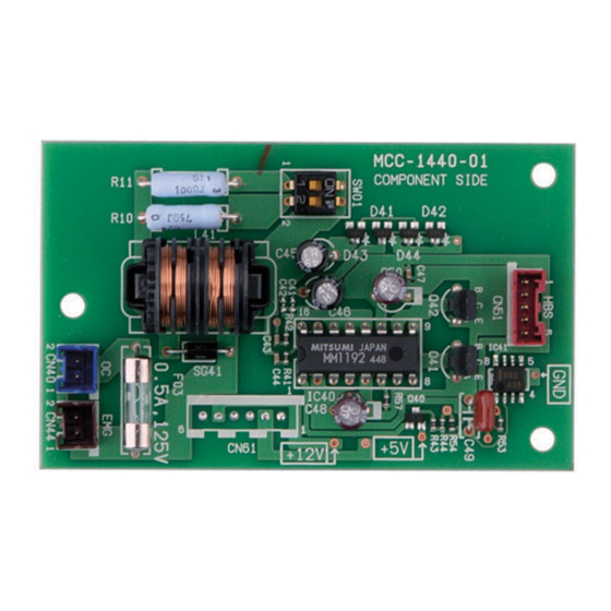
1 : 1 model connection interface board
1
2P terminal block for relay (U3, U4)
For connection of "1 : 1 Model" Connection Interface board with U3, U4 relay terminal block
1
(Blue connector)
For connection of "1 : 1 Model" Connection Interface board with indoor control board
1
(Red connector)
1
This manual
For fixing "1 : 1 Model" Connection Interface board
3
(Used when installing P.C. board on sheet metal of the electric parts box of indoor unit)
1
For fixing "1 : 1 Model" Connection Interface board (Required according to shape of indoor unit)
2
For fixing relay terminal block (M4 × 14L)
3
Used to process wires
1
To be adhered near the relay terminal block
MODEL : TCB-PCNT30TLE2
WARNING
CAUTION
∗∗
∗
4UT
) or you will also purchase the compact 4-
Application
1
Use for Indoor Unit Only
Advertisement
Table of Contents

Related Manuals for Toshiba TCB-PCNT30TLE2


Summary of Contents for Toshiba TCB-PCNT30TLE2
-
Page 1: Installation Manual
INSTALLATION MANUAL Digital Inverter Air Conditioner Use for Indoor Unit Only “1 : 1 Model” Connection Interface MODEL : TCB-PCNT30TLE2 [For Installation Professionals] • Before installation work, please read this manual thoroughly and install the products correctly. Precaution for safety WARNING •... -
Page 2: Before Installation
Before Installation This interface corresponds to the digital inverter air conditioner. Do not use or connect this interface for other type of air conditioner than the above because the indoor P.C. boards of other air conditioners differ from one of the digital inverter air conditioner. Wiring Connection 1. -
Page 3: Wire Specifications
2. Wire Specifications No. of wires Size Specifications Up to 1000m, braided wire 1.25mm 2-core shield wire Up to 2000m, braided wire 2.0mm • Wire is 2-core and non-polarity. • The length is same to wire length of the central control system. In case of system mixed with VRF type, the length includes all length of control wiring between indoor unit and outdoor units at VRFside. - Page 4 Setup of P.C. Board Switch When the units controlled collectively are all digital inverter air conditioners, it is required to set up the terminator resistor. (Collective control for units without VRF type air conditioner) • Using SW01, set up the terminator resistor. •...
-
Page 5: Installation Procedure
Installation Procedure • For installation of “1 : 1 Model” Connection Interface board and removal of relay wire, be sure to wait for a while (approx. 1 minute) after turning off the power supplies of the air conditioner and the collective control devices. If not doing so, “1 : 1 Model”... - Page 6 Procedure Details Using a screw (M4 × 14) of “TCB-PX30MUE” sold separately, install 1:1 Model Connection Interface board box which was prepared in item No.1 at the Screw (M4 Screw (M4 ×14) Screw (M4 ×14) position where the bell-mouth was cut off. (Attached to the TCB-PX30MUE) (Attached to the TCB-PX30MUE) (Attached to the TCB-PX30MUE)
- Page 7 4-way Cassette type ∗∗ ∗∗ ∗∗ ∗∗ ∗∗ ∗∗∗ ∗∗∗ ∗∗∗ ∗∗∗ (RAV-SM 3UT-E, RAV-SM ∗∗∗ ∗∗∗ ∗∗∗ UT-K, RAV-SM ∗∗∗ ∗∗∗ ∗∗∗ UT-4C) Procedure Using board installing spacer (A), install “1 : 1 Model” Connection Interface board to the position of electric parts box of the indoor unit.
-
Page 8: Compact 4-Way Cassette Type
Compact 4-way Cassette type RAV-SM ∗∗∗ ∗∗∗ MUT∗ ∗ ∗ ∗ ∗ ∗∗∗ ∗∗∗ ∗∗∗ CAUTION In case to install 1:1 Model Connection Interface, be sure to purchase also “TCB-PX30MUE” sold separately. For installation, 1:1 Model Connection Interface board box of “TCB-PX30MUE” is necessary. - Page 9 Procedure Details Remove the 2P terminal block for the communication wire of (A), (B) terminals (Connecting the electric parts box on the unit, and then replace with the 4P for the Remote Controller) terminal block of the “TCB-PX30MUE” sold separately for the communication wire.
-
Page 10: Concealed Duct Standard Type
Concealed Duct Standard type ∗∗ ∗∗ ∗∗ ∗∗ ∗∗ ∗∗ ∗∗ ∗∗ ∗∗ ∗∗ (RAV-SM 4BT-E, RAV-SM 1BT-4C) Procedure Using board installing spacer (A), install “1 : 1 Model” Connection Interface board to the position of electric parts box of the indoor unit. -
Page 11: Concealed Duct Type
Concealed Duct type (RAV-SM ∗∗ ∗∗ ∗∗ ∗∗ ∗∗ ∗ ∗ ∗ ∗ ∗ Procedure Take off screws and then remove the terminal block assembly while sliding Using board installing spacer (A) 3 pcs install “1 : 1 Model” Connection Interface board to the position of electric parts box of the indoor unit. -
Page 12: Slim Duct Type
Slim Duct type (RAV-SM ∗∗ ∗∗ ∗∗ ∗∗ ∗∗ 4SDT ∗ ∗ ∗ ∗ ∗ Procedure Using board installing spacer (A) 3 pcs install “1 : 1 Model” Connection Interface board to the position of electric parts box of the indoor unit. (See the figure below.) Using terminal block fixing screws, install U3, U4 terminal block to the position of electric parts box of the indoor unit. -
Page 13: Ceiling Type
Ceiling type (RAV-SM ∗∗ ∗∗ ∗∗ ∗∗ ∗∗ ∗ ∗ ∗ ∗ ∗ , RAV-SM ∗∗ ∗∗ ∗∗ ∗∗ ∗∗ 1CT-4C) Procedure Using board installing spacer (A), install “1 : 1 Model” Connection Interface board to the position of electric parts box of the indoor unit. - Page 14 Concealed Duct Higth Static Pressure Type (RAV-SM ∗∗∗ ∗∗∗ ∗∗∗ 4DTP ∗ ∗ ∗ ∗ ∗ ∗∗∗ ∗∗∗ Procedure Take off the screws A and B then remove the terminal block assembly. Using board installing spacer (A), install “1 : 1 Model” Connection Interface board to the position of electric parts box of the indoor unit.
- Page 15 Ceiling type (RAV-SM ∗∗ ∗∗ ∗∗ ∗∗ ∗∗ ∗ ∗ ∗ ∗ ∗ Procedure Using board installing spacer (A), install “1 : 1 Model” Connection Interface board to the position of electric parts box of the indoor unit. (See the figure below.) Using terminal block fixing screws, install U3, U4 terminal block to the position of electric parts box of the indoor unit.
-
Page 16: Other Cautions
Usage • Refer to Owner’s Manual for the central control devices (TCB-SC642TLE2, TCB-CC163TLE2 etc.) Other Cautions • In a group operation, be sure to turn on power supplies of all the indoor units in group control. (Within 3 min- utes) When power supply of the Header unit is not turned on, there is a possibility that the Header unit exchanges with Follower unit. - Page 17 Manual Setup/Change of Line Address in Indoor Unit [In case of 29 refrigerant lines or less (Includes No. of refrigerant lines at Multi side if mixed)] After the system power supply has been turned on, all the line addresses are allocated to “1” by automatic address setup except group control.
- Page 18 Manual Setup/Change of Line Address in Indoor Unit [In case of 30 refrigerant lines or more (Includes No. of refrigerant lines at Multi side if mixed)] After the system power supply has been turned on, all the line addresses are allocated to “1” by automatic address setup except group control.
- Page 19 Check and Change of Group Address of Indoor Unit In group control or twin, triple, double twin operation, the group address is allocated to indoor unit by automatic address setup after the system power supply has been turned on. From these addresses, “Header unit”: “1” and “Follower unit”: “2”...
- Page 20 Push button (left side of the button), and then turn on fan of the indoor unit which is UNIT LOUVER attached with interface. Leave the CODE No. as it is. (Select CODE No. 14.) Check that the setup data is 0002, and then change the setup data to 0001 using the timer time buttons.
- Page 21 Determination of indoor address Automatic setup Is automatic address set up? Manual setup Setup from central remote controller Setup from wired remote controller Manual address setup from Manual address setup with CODE No. Automatic address setup with wired remote controller “C1”...
-
Page 22: Group Address
Address Setup/Change Method CODE No. R.C. TEMP. ON / OFF 3, 6, 9 TIMER SET MODE 4, 7, 10 TIME SAVE VENT 5, 8, 11 FILTER RESET TEST SWING/FIX UNIT LOUVER <Procedure> TEST Push buttons 2, 12, 13 simultaneously for 4 seconds or more. LCD changes to flashing. - Page 23 Alarm code when addresses are overlapped Procedure Alarm code Case 1 When line addresses are overlapped Wired remote controller side Line 1: E08 Line 2: E08 Line 1 Line 2 Central Central remote controller side control device E08 to Line 1 or Line 2 Outdoor Outdoor Indoor...
- Page 24 TOSHIBA CARRIER CORPORATION 336 TADEHARA, FUJI-SH, SHIZUOKA-KEN 416-8521 JAPAN EH99845701-5...