
Related Manuals for GE P642


Summary of Contents for GE P642
- Page 1 GE Energy Connections Grid Solutions MiCOM P40 Agile P642, P643, P645 Technical Manual Transformer Protection IED Hardware Version: M, P Software Version: 06 Publication Reference: P64x-TM-EN-1.3...
-
Page 3: Table Of Contents
Contents Chapter 1 Introduction Chapter Overview Foreword Target Audience Typographical Conventions Nomenclature Product Scope Product Versions Ordering Options Features and Functions Protection Functions Control Functions Measurement Functions Communication Functions Compliance Functional Overview Chapter 2 Safety Information Chapter Overview Health and Safety Symbols Installation, Commissioning and Servicing Lifting Hazards... - Page 4 Contents P64x 4.1.6 Function Keys 4.1.7 Programable LEDs Rear Panel Boards and Modules PCBs Subassemblies Main Processor Board Power Supply Board 6.4.1 Watchdog 6.4.2 Rear Serial Port Input Module - 1 Transformer Board 6.5.1 Input Module Circuit Description 6.5.2 Frequency Response 6.5.3 Transformer Board 6.5.4...
- Page 5 P64x Contents Navigating the HMI Panel Getting Started Default Display Default Display Navigation Password Entry Processing Alarms and Records Menu Structure Changing the Settings Direct Access (The Hotkey menu) 2.9.1 Setting Group Selection Using Hotkeys 2.9.2 Control Inputs 2.10 Function Keys Configuring the Data Protocols Courier Configuration DNP3 Configuration...
- Page 6 Contents P64x Differential Biased Trip Logic Harmonic Blocking 2nd Harmonic Blocking 2nd Harmonic Blocking Logic 5th Harmonic Blocking Implementation 5th Harmonic Setting Guideline Geomagnetic Disturbances Overall Harmonic Blocking Logic Application Notes Setting Guidelines Example 1: Two-winding Transformer - No Tap Changer Example 2: Autotransformer with Loaded Delta Winding Example 3: Autotransformer with Unloaded Delta Winding Setting Guidelines for Short-Interconnected Biased Differential Protection...
- Page 7 P64x Contents CLO Implementation Application Notes 6.4.1 CLI Setting Guidelines 6.4.2 CLO Setting Guidelines Chapter 8 Restricted Earth Fault Protection Chapter Overview REF Protection Principles Resistance-Earthed Star Windings Solidly-Earthed Star Windings Through Fault Stability Restricted Earth Fault Types 2.4.1 Low Impedance REF Principle 2.4.2 High Impedance REF Principle Restricted Earth Fault Protection Implementation...
- Page 8 Contents P64x Non-Directional Overcurrent Logic Directional Element 3.5.1 Implementing Directionalisation 3.5.2 Directional Overcurrent Logic Application Notes 3.6.1 Setting Guidelines 3.6.2 Parallel Feeders Voltage Dependent Overcurrent Element Current Setting Threshold Selection VCO Implementation Negative Sequence Overcurrent Protection NPSOC Protection Implementation Non-Directional NPSOC Logic Directional Element 5.3.1 Directional NPSOC Logic...
- Page 9 P64x Contents 2.3.1 Undervoltage Setting Guidelines Overvoltage Protection Overvoltage Protection Implementation Overvoltage Protection Logic Application Notes 3.3.1 Overvoltage Setting Guidelines Residual Overvoltage Protection Residual Overvoltage Protection Implementation Residual Overvoltage Logic Application Notes 4.3.1 Calculation for Solidly Earthed Systems 4.3.2 Calculation for Impedance Earthed Systems 4.3.3 Setting Guidelines Negative Sequence Overvoltage Protection...
- Page 10 Contents P64x 4.1.4 Demand Values 4.1.5 Other Measurements Measurement Setup Opto-input Time Stamping Current Input Exclusion Function Current Input Exclusion Logic Application Notes 5.2.1 Current Input Exclusion Example Pole Dead Function Pole Dead Function Implementation Pole Dead Logic CB Status Indication Chapter 14 Supervision Chapter Overview...
- Page 11 P64x Contents Communication Interfaces Serial Communication EIA(RS)232 Bus EIA(RS)485 Bus 3.2.1 EIA(RS)485 Biasing Requirements K-Bus Standard Ethernet Communication Hot-Standby Ethernet Failover Redundant Ethernet Communication Supported Protocols Parallel Redundancy Protocol Rapid Spanning Tree Protocol Self Healing Protocol Dual Homing Protocol Redundant Ethernet Configuration 5.6.1 Setting the NIC IP Address 5.6.2...
- Page 12 Contents P64x 6.4.8 Password Protection 6.4.9 Protection and Disturbance Recorder Settings 6.4.10 Time Synchronisation 6.4.11 Power and Energy Measurement Data Formats 6.4.12 MODBUS Configuration IEC 61850 6.5.1 Benefits of IEC 61850 6.5.2 IEC 61850 Interoperability 6.5.3 The IEC 61850 Data Model 6.5.4 IEC 61850 in MiCOM IEDs 6.5.5...
- Page 13 P64x Contents Security Events Management Logging Out Chapter 18 Installation Chapter Overview Handling the Goods Receipt of the Goods Unpacking the Goods Storing the Goods Dismantling the Goods Mounting the Device Flush Panel Mounting Rack Mounting Cables and Connectors Terminal Blocks Power Supply Connections Earth Connnection Current Transformers...
- Page 14 Contents P64x Advisory Test Equipment Product Checks Product Checks with the IED De-energised 5.1.1 Visual Inspection 5.1.2 Current Transformer Shorting Contacts 5.1.3 Insulation 5.1.4 External Wiring 5.1.5 Watchdog Contacts 5.1.6 Power Supply Product Checks with the IED Energised 5.2.1 Watchdog Contacts 5.2.2 Test LCD 5.2.3...
- Page 15 P64x Contents Replacing PCBs 2.5.1 Replacing the main processor board 2.5.2 Replacement of communications boards 2.5.3 Replacement of the input module 2.5.4 Replacement of the power supply board 2.5.5 Replacement of the I/O boards Recalibration Changing the battery 2.7.1 Post Modification Tests 2.7.2 Battery Disposal Cleaning...
- Page 16 Contents P64x Negative Sequence Overcurrent Protection 4.5.1 NPSOC Directional Parameters Circuit Breaker Fail Protection Performance of Voltage Protection Functions Undervoltage Protection (P643/5) Overvoltage Protection Residual Overvoltage Protection (P643/5) Negative Sequence Voltage Protection Performance of Frequency Protection Functions Overfrequency Protection Underfrequency Protection Overfluxing Protection Performance of Monitoring and Control Functions Voltage Transformer Supervision...
- Page 17 P64x Contents 15.2 Creepage Distances and Clearances 15.3 High Voltage (Dielectric) Withstand 15.4 Impulse Voltage Withstand Test Electromagnetic Compatibility 16.1 1 MHz Burst High Frequency Disturbance Test 16.2 Damped Oscillatory Test 16.3 Immunity to Electrostatic Discharge 16.4 Electrical Fast Transient or Burst Requirements 16.5 Surge Withstand Capability 16.6...
- Page 18 Contents P64x P64x-TM-EN-1.3...
- Page 19 Table of Figures Figure 1: P64x version evolution Figure 2: Functional overview Figure 3: Hardware architecture Figure 4: Exploded view of IED Figure 5: Front panel (60TE) Figure 6: HMI panel Figure 7: Rear view of populated case Figure 8: Terminal block types Figure 9: Rear connection to terminal block...
- Page 20 Differential protection blocking mechanisms Figure 51: Triple slope characteristic Figure 52: P642 used to protect a two winding transformer Figure 53: P645 used to protect an autotransformer with loaded delta winding Figure 54: P643 used to protect an autotransformer with unloaded delta winding Figure 55: Unloaded delta –...
- Page 21 P64x Table of Figures Figure 79: Low impedance restricted Earth Fault logic Figure 80: REF 2nd harmonic blocking logic Figure 81: Star winding, resistance earthed Figure 82: Percentage of winding protected Figure 83: Low Impedance REF Scaling Factor Figure 84: Low-Z REF for dual CB application with different phase CT ratios Figure 85: Low-Z REF for dual CB application with same phase CT ratios...
- Page 22 Figure 129: Pole Dead logic - P643 and P645 Figure 130: Forcing CB Closed signals Figure 131: VTS logic (P642 with 2 single-phase VTs) Figure 132: VTS logic (P643 and P645 with 3-phase VTs) Figure 133: CTS restraint region increase...
- Page 23 P64x Table of Figures Figure 157: Automatic selection of disturbance record - method 2 Figure 158: Configuration file extraction Figure 159: Data file extraction Figure 160: Data model layers in IEC61850 Figure 161: GPS Satellite timing signal Figure 162: Default display navigation Figure 163: Location of battery isolation strip Figure 164:...
- Page 24 Table of Figures P64x xxii P64x-TM-EN-1.3...
-
Page 25: Chapter 1 Introduction
CHAPTER 1 INTRODUCTION... -
Page 26: Rear Serial Port
Chapter 1 - Introduction P64x P64x-TM-EN-1.3... -
Page 27: Chapter Overview
P64x Chapter 1 - Introduction CHAPTER OVERVIEW This chapter provides some general information about the technical manual and an introduction to the device(s) described in this technical manual. This chapter contains the following sections: Chapter Overview Foreword Product Scope Features and Functions Compliance Functional Overview P64x-TM-EN-1.3... -
Page 28: Foreword
P64x FOREWORD This technical manual provides a functional and technical description of GE's P642, P643, P645, as well as a comprehensive set of instructions for using the device. The level at which this manual is written assumes that you are already familiar with protection engineering and have experience in this discipline. The description of principles and theory is limited to that which is necessary to understand the product. -
Page 29: Nomenclature
Some of these terms are well-known industry-specific terms while others may be special product- specific terms used by GE. The first instance of any acronym or term used in a particular chapter is explained. In addition, a separate glossary is available on the GE website, or from the GE contact centre. -
Page 30: Product Scope
3-phase VT input. The P64x range consists of three models; the P642, P643, and P645. The P642 provides 8 on-board CTs to support two-winding 3-phase power transformers and 1or 2 single- ●... -
Page 31: Ordering Options
P64x Chapter 1 - Introduction J, K Hardware version K (P645SV) Hardware version J (P642), K (P643/5) Software version 12 Software version 04 · · Hot-Standby Ethernet Failover Negative Sequence Overvoltage · · Cyber Security Voltage Controlled Overcurrent · ·... -
Page 32: Features And Functions
Chapter 1 - Introduction P64x FEATURES AND FUNCTIONS PROTECTION FUNCTIONS The P64x range of devices provides the following protection functions: ANSI IEC 61850 Protection Function P642 P643 P645 LzdPDIF Transformer biased differential protection • • • RefPDIF Low Impedance and High Impedance Restricted Earth Fault protection... -
Page 33: Measurement Functions
P64x Chapter 1 - Introduction Feature IEC 61850 ANSI Trip circuit and coil supervision Control inputs PloGGIO1 Power-up diagnostics and continuous self-monitoring Dual rated 1A and 5A CT inputs Alternative setting groups (4) Graphical programmable scheme logic (PSL) MEASUREMENT FUNCTIONS Measurement Function IEC 61850 ANSI... -
Page 34: Compliance
Chapter 1 - Introduction P64x COMPLIANCE The device has undergone a range of extensive testing and certification processes to ensure and prove compatibility with all target markets. A detailed description of these criteria can be found in the Technical Specifications chapter. P64x-TM-EN-1.3... -
Page 35: Functional Overview
P64x Chapter 1 - Introduction FUNCTIONAL OVERVIEW Remote Local 2nd Remote Fault records Ethernet Communication Comm. port Comm. port Disturbance Record I-HV Measurements Self monitoring IN-HV IN-LV IDMT VCO DT VCO I-LV DIFF Thru IN-TV I-TV virtual I-TV Always Available Transformer Differential BINARY CLIO... - Page 36 Chapter 1 - Introduction P64x P64x-TM-EN-1.3...
-
Page 37: Chapter 2 Safety Information
CHAPTER 2 SAFETY INFORMATION... - Page 38 Chapter 2 - Safety Information P64x P64x-TM-EN-1.3...
-
Page 39: Chapter Overview
P64x Chapter 2 - Safety Information CHAPTER OVERVIEW This chapter provides information about the safe handling of the equipment. The equipment must be properly installed and handled in order to maintain it in a safe condition and to keep personnel safe at all times. You must be familiar with information contained in this chapter before unpacking, installing, commissioning, or servicing the equipment. -
Page 40: Health And Safety
Chapter 2 - Safety Information P64x HEALTH AND SAFETY Personnel associated with the equipment must be familiar with the contents of this Safety Information. When electrical equipment is in operation, dangerous voltages are present in certain parts of the equipment. Improper use of the equipment and failure to observe warning notices will endanger personnel. -
Page 41: Symbols
P64x Chapter 2 - Safety Information SYMBOLS Throughout this manual you will come across the following symbols. You will also see these symbols on parts of the equipment. Caution: Refer to equipment documentation. Failure to do so could result in damage to the equipment Warning: Risk of electric shock... -
Page 42: Installation, Commissioning And Servicing
Chapter 2 - Safety Information P64x INSTALLATION, COMMISSIONING AND SERVICING LIFTING HAZARDS Many injuries are caused by: Lifting heavy objects ● Lifting things incorrectly ● ● Pushing or pulling heavy objects Using the same muscles repetitively ● Plan carefully, identify any possible hazards and determine how best to move the product. Look at other ways of moving the load to avoid manual handling. -
Page 43: Ul/Csa/Cul Requirements
P64x Chapter 2 - Safety Information Caution: NEVER look into optical fibres or optical output connections. Always use optical power meters to determine operation or signal level. Warning: Testing may leave capacitors charged to dangerous voltage levels. Discharge capacitors by rediucing test voltages to zero before disconnecting test leads. Caution: Operate the equipment within the specified electrical and environmental limits. -
Page 44: Equipment Connections
Chapter 2 - Safety Information P64x Caution: Digital input circuits should be protected by a high rupture capacity NIT or TIA fuse with maximum rating of 16 A. for safety reasons, current transformer circuits must never be fused. Other circuits should be appropriately fused to protect the wire used. Caution: CTs must NOT be fused since open circuiting them may produce lethal hazardous voltages... -
Page 45: Pre-Energisation Checklist
P64x Chapter 2 - Safety Information Caution: Use a locknut or similar mechanism to ensure the integrity of stud-connected PCTs. Caution: The recommended minimum PCT wire size is 2.5 mm² for countries whose mains supply is 230 V (e.g. Europe) and 3.3 mm² for countries whose mains supply is 110 V (e.g. North America). -
Page 46: Upgrading/Servicing
Chapter 2 - Safety Information P64x Note: For most Alstom equipment with ring-terminal connections, the threaded terminal block for current transformer termination is automatically shorted if the module is removed. Therefore external shorting of the CTs may not be required. Check the equipment documentation and wiring diagrams first to see if this applies. -
Page 47: Decommissioning And Disposal
P64x Chapter 2 - Safety Information DECOMMISSIONING AND DISPOSAL Caution: Before decommissioning, completely isolate the equipment power supplies (both poles of any dc supply). The auxiliary supply input may have capacitors in parallel, which may still be charged. To avoid electric shock, discharge the capacitors using the external terminals before decommissioning. -
Page 48: Standards Compliance
Chapter 2 - Safety Information P64x STANDARDS COMPLIANCE Compliance with the European Commission Directive on EMC and LVD is demonstrated by self certification against international standards. EMC COMPLIANCE: 2004/108/EC Compliance with EN60255-26:2009 was used to establish conformity. PRODUCT SAFETY: 2006/95/EC Compliance with EN60255-27:2005 was used to establish conformity. - Page 49 P64x Chapter 2 - Safety Information Compliance demonstrated by Notified Body Type Examination Certificate. ATEX Potentially Explosive Atmospheres directive 94/9/EC for equipment. P64x-TM-EN-1.3...
- Page 50 Chapter 2 - Safety Information P64x P64x-TM-EN-1.3...
-
Page 51: Chapter 3 Hardware Design
CHAPTER 3 HARDWARE DESIGN... - Page 52 Chapter 3 - Hardware Design P64x P64x-TM-EN-1.3...
-
Page 53: Chapter Overview
P64x Chapter 3 - Hardware Design CHAPTER OVERVIEW This chapter provides information about the product's hardware design. This chapter contains the following sections: Chapter Overview Hardware Architecture Mechanical Implementation Front Panel Rear Panel Boards and Modules P64x-TM-EN-1.3... -
Page 54: Hardware Architecture
Chapter 3 - Hardware Design P64x HARDWARE ARCHITECTURE The main components comprising devices based on the Px4x platform are as follows: The housing, consisting of a front panel and connections at the rear ● The Main processor module consisting of the main CPU (Central Processing Unit), memory and an interface ●... -
Page 55: Mechanical Implementation
P64x Chapter 3 - Hardware Design MECHANICAL IMPLEMENTATION All products based on the Px4x platform have common hardware architecture. The hardware is modular and consists of the following main parts: Case and terminal blocks ● Boards and modules ● Front panel ●... -
Page 56: List Of Boards
Chapter 3 - Hardware Design P64x Case width (TE) Case width (mm) Case width (inches) 40TE 203.2 60TE 304.8 80TE 406.4 Note: Not all case sizes are available for all models. LIST OF BOARDS The product's hardware consists of several modules drawn from a standard range. The exact specification and number of hardware modules depends on the model number and variant. - Page 57 P64x Chapter 3 - Hardware Design Board RTD board Contains 10 Resistive Temperature Device inputs CLIO board Contains 4 current loop inputs and 4 current loop outputs High Break Output Relay Board Output relay board with high breaking capacity relays P64x-TM-EN-1.3...
-
Page 58: Front Panel
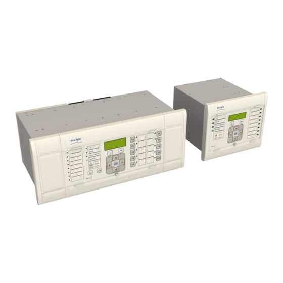
Chapter 3 - Hardware Design P64x FRONT PANEL FRONT PANEL Depending on the exact model and chosen options, the product will be housed in either a 40TE, 60TE or 80TE case. By way of example, the following diagram shows the front panel of a typical 60TE unit. The front panels of the products based on 40TE and 80TE cases have a lot of commonality and differ only in the number of hotkeys and user-programmable LEDs. -
Page 59: Hmi Panel
P64x Chapter 3 - Hardware Design The bottom compartment contains: A compartment for a 1/2 AA size backup battery (used to back up the real time clock and event, fault, and ● disturbance records). A 9-pin female D-type front port for an EIA(RS)232 serial connection to a PC. ●... -
Page 60: Front Parallel Port (Sk2)
Chapter 3 - Hardware Design P64x The inactivity timer for the front port is set to 15 minutes. This controls how long the unit maintains its level of password access on the front port. If no messages are received on the front port for 15 minutes, any password access level that has been enabled is cancelled. -
Page 61: Programable Leds
P64x Chapter 3 - Hardware Design 4.1.7 PROGRAMABLE LEDS The device has a number of programmable LEDs, which can be associated with PSL-generated signals. The programmable LEDs for most models are tri-colour and can be set to RED, YELLOW or GREEN. However the programmable LEDs for some models are single-colour (red) only. -
Page 62: Rear Panel
Chapter 3 - Hardware Design P64x REAR PANEL The MiCOM Px40 series uses a modular construction. Most of the internal workings are on boards and modules which fit into slots. Some of the boards plug into terminal blocks, which are bolted onto the rear of the unit. However, some boards such as the communications boards have their own connectors. -
Page 63: Figure 8: Terminal Block Types
P64x Chapter 3 - Hardware Design Figure 8: Terminal block types Note: Not all products use all types of terminal blocks. The product described in this manual may use one or more of the above types. P64x-TM-EN-1.3... -
Page 64: Boards And Modules
Chapter 3 - Hardware Design P64x BOARDS AND MODULES Each product comprises a selection of PCBs (Printed Circuit Boards) and subassemblies, depending on the chosen configuration. PCBS A PCB typically consists of the components, a front connector for connecting into the main system parallel bus via a ribbon cable, and an interface to the rear. -
Page 65: Main Processor Board
P64x Chapter 3 - Hardware Design The products in the Px40 series typically contain two sub-assemblies: The power supply assembly comprising: ● ○ A power supply board An output relay board ○ The input module comprising: ● One or more transformer boards, which contains the voltage and current transformers (partially or ○... -
Page 66: Power Supply Board
Chapter 3 - Hardware Design P64x POWER SUPPLY BOARD Figure 11: Power supply board The power supply board provides power to the unit. One of three different configurations of the power supply board can be fitted to the unit. This is specified at the time of order and depends on the magnitude of the supply voltage that will be connected to it. -
Page 67: Figure 12: Power Supply Assembly
P64x Chapter 3 - Hardware Design Figure 12: Power supply assembly The power supply outputs are used to provide isolated power supply rails to the various modules within the unit. Three voltage levels are used by the unit’s modules: 5.1 V for all of the digital circuits ●... -
Page 68: Watchdog
Chapter 3 - Hardware Design P64x Figure 13: Power supply terminals 6.4.1 WATCHDOG The Watchdog contacts are also hosted on the power supply board. The Watchdog facility provides two output relay contacts, one normally open and one normally closed. These are used to indicate the health of the device and are driven by the main processor board, which continually monitors the hardware and software when the device is in service. -
Page 69: Rear Serial Port
P64x Chapter 3 - Hardware Design Figure 14: Watchdog contact terminals 6.4.2 REAR SERIAL PORT The rear serial port (RP1) is housed on the power supply board. This is a three-terminal EIA(RS)485 serial communications port and is intended for use with a permanently wired connection to a remote control centre for SCADA communication. -
Page 70: Input Module - 1 Transformer Board
Chapter 3 - Hardware Design P64x Figure 15: Rear serial port terminals An additional serial port with D-type presentation is available as an optional board, if required. INPUT MODULE - 1 TRANSFORMER BOARD Figure 16: Input module - 1 transformer board The input module consists of the main input board coupled together with an instrument transformer board. -
Page 71: Input Module Circuit Description
P64x Chapter 3 - Hardware Design 6.5.1 INPUT MODULE CIRCUIT DESCRIPTION 8 digital inputs Optical Optical Isolator Isolator Noise Noise filter filter Parallel Bus Buffer Transformer board Serial Link Serial A/D Converter interface V00239 Figure 17: Input module schematic A/D Conversion The differential analogue inputs from the CT and VT transformers are presented to the main input board as shown. -
Page 72: Frequency Response
Chapter 3 - Hardware Design P64x Note: The opto-input circuitry can be provided without the A/D circuitry as a separate board, which can provide supplementary opto-inputs. 6.5.2 FREQUENCY RESPONSE With the exception of the RMS measurements, all other measurements and protection functions are based on the Fourier-derived fundamental component. -
Page 73: Transformer Board
P64x Chapter 3 - Hardware Design 6.5.3 TRANSFORMER BOARD Figure 19: Transformer board The transformer board hosts the current and voltage transformers. These are used to step down the currents and voltages originating from the power systems' current and voltage transformers to levels that can be used by the devices' electronic circuitry. -
Page 74: Input Board
Chapter 3 - Hardware Design P64x 6.5.4 INPUT BOARD Figure 20: Input board The input board is used to convert the analogue signals delivered by the current and voltage transformers into digital quantities used by the IED. This input board also has on-board opto-input circuitry, providing eight optically- isolated digital inputs and associated noise filtering and buffering. -
Page 75: Standard Output Relay Board
P64x Chapter 3 - Hardware Design Terminal Number Opto-input Terminal 17 Common Terminal 18 Common STANDARD OUTPUT RELAY BOARD Figure 21: Standard output relay board - 8 contacts This output relay board has 8 relays with 6 Normally Open contacts and 2 Changeover contacts. The output relay board is provided together with the power supply board as a complete assembly, or independently for the purposes of relay output expansion. -
Page 76: Irig-B Board
Chapter 3 - Hardware Design P64x Terminal Number Output Relay Terminal 11 Relay 6 NO Terminal 12 Relay 6 NO Terminal 13 Relay 7 changeover Terminal 14 Relay 7 changeover Terminal 15 Relay 7 common Terminal 16 Relay 8 changeover Terminal 17 Relay 8 changeover Terminal 18... -
Page 77: Fibre Optic Board
P64x Chapter 3 - Hardware Design FIBRE OPTIC BOARD Figure 23: Fibre optic board This board provides an interface for communicating with a master station. This communication link can use all compatible protocols (Courier, IEC 60870-5-103, MODBUS and DNP 3.0). It is a fibre-optic alternative to the metallic RS485 port presented on the power supply terminal block. -
Page 78: Rear Communication Board
Chapter 3 - Hardware Design P64x REAR COMMUNICATION BOARD Figure 24: Rear communication board The optional communications board containing the secondary communication ports provide two serial interfaces presented on 9 pin D-type connectors. These interfaces are known as SK4 and SK5. Both connectors are female connectors, but are configured as DTE ports. - Page 79 P64x Chapter 3 - Hardware Design This is a communications board that provides a standard 100-Base Ethernet interface. This board supports one electrical copper connection and one fibre-pair connection. There are several variants for this board as follows: 100 Mbps Ethernet board ●...
-
Page 80: Redundant Ethernet Board
Chapter 3 - Hardware Design P64x 6.11 REDUNDANT ETHERNET BOARD IRIG-B Link Fail Pin3 connector Pin 2 Pin 1 Link channel B Link channel A (green LED) (green LED) Activity channel Activity channel B A (yellow LED) (yellow LED) V01009 Figure 26: Redundant Ethernet board This board provides dual redundant Ethernet (supported by two fibre pairs) together with an IRIG-B interface for timing. - Page 81 P64x Chapter 3 - Hardware Design LEDs Function Flashing Green Link Link ok Link broken Yellow Activity SHP running PRP, RSTP or DHP traffic Optical Fibre Connectors (ST) Connector RSTP RJ45connector Signal name Signal definition Transmit (positive) Transmit (negative) Receive (positive) Not used Not used Receive (negative)
-
Page 82: Rtd Board
Chapter 3 - Hardware Design P64x 6.12 RTD BOARD Figure 27: RTD board The RTD board provides two banks of 15 terminals to support ten RTD inputs, of the type PT100, Ni100, or Ni120, depending on the product. There are three terminals for each RTD, therefore 30 terminals altogether. The RTD board fits into slot B or slot C, depending on the model variant. -
Page 83: Clio Board
P64x Chapter 3 - Hardware Design Terminal Number RTD connection Terminal 17 RTD6 wire 2 Terminal 18 RTD6 wire 3 Terminal 19 RTD7 wire 1 Terminal 20 RTD7 wire 2 Terminal 21 RTD7 wire 3 Terminal 22 RTD8 wire 1 Terminal 23 RTD8 wire 2 Terminal 24... - Page 84 Chapter 3 - Hardware Design P64x Terminal Number Current Loop Connection Terminal 1 CLO1 - 20 mA input Terminal 2 CLO1 - 1 mA input Terminal 3 CLO1 - common input Terminal 4 Not used Terminal 5 CLO2 - 20 mA input Terminal 6 CLO2 - 1 mA input Terminal 7...
-
Page 85: High Break Output Relay Board
P64x Chapter 3 - Hardware Design 6.14 HIGH BREAK OUTPUT RELAY BOARD Figure 29: High Break relay output board A High Break output relay board is available as an option. It comprises four normally open output contacts, which are suitable for high breaking loads. A High Break contact consists of a high capacity relay with a MOSFET in parallel with it. -
Page 86: Figure 30: High Break Contact Operation
Chapter 3 - Hardware Design P64x Databus control input MOSFET operate MOSFET reset Relay contact Closed 3.5ms + contact bounce 3.5ms Load current V00246 Figure 30: High Break contact operation High Break Contact Applications Efficient scheme engineering ● In traditional hard wired scheme designs, High Break capability could only be achieved using external electromechanical trip relays. -
Page 87: Chapter 4 Software Design
CHAPTER 4 SOFTWARE DESIGN... - Page 88 Chapter 4 - Software Design P64x P64x-TM-EN-1.3...
-
Page 89: Chapter Overview
P64x Chapter 4 - Software Design CHAPTER OVERVIEW This chapter describes the software design of the IED. This chapter contains the following sections: Chapter Overview Sofware Design Overview System Level Software Platform Software Protection and Control Functions P64x-TM-EN-1.3... -
Page 90: Sofware Design Overview
Chapter 4 - Software Design P64x SOFWARE DESIGN OVERVIEW The device software can be conceptually categorized into several elements as follows: The system level software ● The platform software ● ● The protection and control software These elements are not distinguishable to the user, and the distinction is made purely for the purposes of explanation. -
Page 91: System Level Software
P64x Chapter 4 - Software Design SYSTEM LEVEL SOFTWARE REAL TIME OPERATING SYSTEM The real-time operating system is used to schedule the processing of the various tasks. This ensures that they are processed in the time available and in the desired order of priority. The operating system also plays a part in controlling the communication between the software tasks, through the use of operating system messages. -
Page 92: System Level Software Initialisation
Chapter 4 - Software Design P64x 3.4.2 SYSTEM LEVEL SOFTWARE INITIALISATION The initialization process initializes the processor registers and interrupts, starts the watchdog timers (used by the hardware to determine whether the software is still running), starts the real-time operating system and creates and starts the supervisor task. - Page 93 P64x Chapter 4 - Software Design A restart should clear most problems that may occur. If, however, the diagnostic self-check detects the same problem that caused the IED to restart, it is clear that the restart has not cleared the problem, and the device takes itself permanently out of service.
-
Page 94: Platform Software
Chapter 4 - Software Design P64x PLATFORM SOFTWARE The platform software has three main functions: To control the logging of records generated by the protection software, including alarms, events, faults, and ● maintenance records To store and maintain a database of all of the settings in non-volatile memory ●... -
Page 95: Protection And Control Functions
P64x Chapter 4 - Software Design PROTECTION AND CONTROL FUNCTIONS The protection and control software processes all of the protection elements and measurement functions. To achieve this it has to communicate with the system services software, the platform software as well as organise its own operations. -
Page 96: Programmable Scheme Logic
Chapter 4 - Software Design P64x The Fourier components are calculated using single-cycle Fourier algorithm. This Fourier algorithm always uses the most recent 24 samples from the 2-cycle buffer. Most protection algorithms use the fundamental component. In this case, the Fourier algorithm extracts the power frequency fundamental component from the signal to produce its magnitude and phase angle. -
Page 97: Event Recording
P64x Chapter 4 - Software Design EVENT RECORDING A change in any digital input signal or protection element output signal is used to indicate that an event has taken place. When this happens, the protection and control task sends a message to the supervisor task to indicate that an event is available to be processed and writes the event data to a fast buffer controlled by the supervisor task. - Page 98 Chapter 4 - Software Design P64x P64x-TM-EN-1.3...
-
Page 99: Chapter 5 Configuration
CHAPTER 5 CONFIGURATION... - Page 100 Chapter 5 - Configuration P64x P64x-TM-EN-1.3...
-
Page 101: Chapter Overview
P64x Chapter 5 - Configuration CHAPTER OVERVIEW Each product has different configuration parameters according to the functions it has been designed to perform. There is, however, a common methodology used across the entire product series to set these parameters. Some of the communications setup can only be carried out using the HMI, and cannot be carried out using settings applications software. -
Page 102: Using The Hmi Panel
Chapter 5 - Configuration P64x USING THE HMI PANEL Using the HMI, you can: Display and modify settings ● View the digital I/O signal status ● ● Display measurements Display fault records ● Reset fault and alarm indications ● The keypad provides full access to the device functionality using a range of menu options. The information is displayed on the LCD. -
Page 103: Navigating The Hmi Panel
P64x Chapter 5 - Configuration Note: As the LCD display has a resolution of 16 characters by 3 lines, some of the information is in a condensed mnemonic form. NAVIGATING THE HMI PANEL The cursor keys are used to navigate the menus. These keys have an auto-repeat function if held down continuously. -
Page 104: Default Display
Chapter 5 - Configuration P64x Even though the device itself should be in full working order when you first start it, an alarm could still be present, for example, if there is no network connection for a device fitted with a network card. If this is the case, you can read the alarm by pressing the 'Read' key. -
Page 105: Default Display Navigation
P64x Chapter 5 - Configuration Access Level For example: Access Level HOTKEY In addition to the above, there are also displays for the system voltages, currents, power and frequency etc., depending on the device model. DEFAULT DISPLAY NAVIGATION The following diagram is an example of the default display navigation. In this example, we have used a cyber- secure model. -
Page 106: Password Entry
Chapter 5 - Configuration P64x Note: Whenever the IED has an uncleared alarm the default display is replaced by the text Alarms/ Faults present. You cannot override this default display. However, you can enter the menu structure from the default display, even if the display shows the Alarms/Faults present message. -
Page 107: Menu Structure
P64x Chapter 5 - Configuration Press Clear To Reset Alarms To clear all alarm messages, press the Clear key. To return to the display showing alarms or faults present, and leave the alarms uncleared, press the Read key. Depending on the password configuration settings, you may need to enter a password before the alarm messages can be cleared. -
Page 108: Changing The Settings
Chapter 5 - Configuration P64x Setting Column Description Sys Fn Links (Row 03) Third setting within first column … … … VIEW RECORDS Second Column definition Select Event [0...n] First setting within second column Menu Cell Ref Second setting within second column Time &... -
Page 109: Direct Access (The Hotkey Menu)
P64x Chapter 5 - Configuration Note: For the protection group and disturbance recorder settings, if the menu time-out occurs before the changes have been confirmed, the setting values are discarded. Control and support settings, howeverr, are updated immediately after they are entered, without the Update settings? prompt. -
Page 110: Function Keys
Chapter 5 - Configuration P64x Press the right cursor key twice to get to the first control input, or the left cursor key to get to the last control input. ¬STP GP User02® Control Input 1 EXIT SET Now you can execute the chosen function (Set/Reset in this case). If neither of the cursor keys is pressed within 20 seconds of entering a hotkey sub menu, the device reverts to the default display. - Page 111 P64x Chapter 5 - Configuration the bottom line, character by character. This text is displayed when a function key is accessed in the function key menu, or it can be displayed in the PSL. FUNCTION KEYS Fn Key 1 Label Function Key 1 Subsequent cells allow you to carry out the same procedure as above for the other function keys.
-
Page 112: Configuring The Data Protocols
Chapter 5 - Configuration P64x CONFIGURING THE DATA PROTOCOLS Different protocols can be used with the various ports. The choice of protocol depends on the chosen model. Each port can support only one protocol at a time. The range of available communication settings depend on which protocol has been chosen. -
Page 113: Dnp3 Configuration
P64x Chapter 5 - Configuration COMMUNICATIONS RP1 Inactivtimer 10.00 mins. If the optional fibre optic connectors are fitted, the RP1 PhysicalLink cell is visible. This cell controls the physical media used for the communication (Copper or Fibre optic). COMMUNICATIONS RP1 PhysicalLink Copper Move down to the next cell (RP1 Card Status). -
Page 114: Dnp3 Configurator
Chapter 5 - Configuration P64x COMMUNICATIONS RP1 Protocol DNP3.0 Move down to the next cell (RP1 Address). This cell controls the DNP3.0 address of the IED. Up to 32 IEDs can be connected to one spur, therefore it is necessary for each IED to have a unique address so that messages from the master control station are accepted by only one IED. - Page 115 P64x Chapter 5 - Configuration configuration takes effect after the download is complete. To restore the default configuration at any time, from the CONFIGURATION column, select the Restore Defaults cell then select All Settings. In MiCOM S1 Agile, the DNP3.0 data is shown in three main folders, one folder each for the point configuration, integer scaling and default variation (data format).
-
Page 116: Modbus Configuration
Chapter 5 - Configuration P64x COMMUNICATIONS RP1 PhysicalLink Copper The next cell down (RP1 CS103Blcking) can be used for monitor or command blocking. COMMUNICATIONS RP1 CS103Blcking Disabled There are three settings associated with this cell; these are: Setting: Description: Disabled No blocking selected. -
Page 117: Iec 61850 Configuration
P64x Chapter 5 - Configuration COMMUNICATIONS RP1 Inactivtimer 10.00 mins Move down to the next cell (RP1 Baud Rate). This cell controls the baud rate to be used. Six baud rates are supported by the IED 1200 bits/s, 2400 bits/s, 4800 bits/s, 9600 bits/s, 19200 bits/s and 38400 bits/s. Make sure that the baud rate selected on the IED is the same as that set on the master station. -
Page 118: Iec 61850 Configuration Banks
Chapter 5 - Configuration P64x Note: Some configuration data is available in the IEC61850 CONFIG. column, allowing read-only access to basic configuration data. 3.5.1 IEC 61850 CONFIGURATION BANKS There are two configuration banks: Active Configuration Bank ● Inactive Configuration Bank ●... -
Page 119: Date And Time Configuration
P64x Chapter 5 - Configuration DATE AND TIME CONFIGURATION The date and time setting will normally be updated automatically by the chosen UTC (Universal Time Co- ordination) time synchronisation mechanism when the device is in service. You can also set the date and time manually using the Date/Time cell in the DATE AND TIME column. -
Page 120: Phase Rotation
Chapter 5 - Configuration P64x PHASE ROTATION The product provides a facility to maintain correct operation of all the protection functions even when the system is running in a reverse phase sequence. This is achieved by the Phase Sequence setting in the SYSTEM CONFIG column, and is available for all four setting groups. -
Page 121: Chapter 6 Transformer Differential Protection
CHAPTER 6 TRANSFORMER DIFFERENTIAL PROTECTION... - Page 122 Chapter 6 - Transformer Differential Protection P64x P64x-TM-EN-1.3...
-
Page 123: Chapter Overview
P64x Chapter 6 - Transformer Differential Protection CHAPTER OVERVIEW This chapter contains the following sections: Chapter Overview Transformer Differential Protection Principles Implementation Harmonic Blocking Application Notes P64x-TM-EN-1.3... -
Page 124: Transformer Differential Protection Principles
Chapter 6 - Transformer Differential Protection P64x TRANSFORMER DIFFERENTIAL PROTECTION PRINCIPLES Transformer Differential Protection (87T) uses the well-known current differential principle where current entering the protected equipment is compared with the current leaving the protected equipment. If there is no fault, the current entering the transformer will be equal to the current leaving the transformer multiplied by the inverse of the turns ratio. -
Page 125: Three-Phase Transformer Connection Types
P64x Chapter 6 - Transformer Differential Protection CTs may be close to saturation so a high bias current is needed. More differential current is then needed to trip the circuit breakers, allowing greater security from external faults and less risk of maloperation. This is achieved by defining an operating current characteristic. - Page 126 Chapter 6 - Transformer Differential Protection P64x Not only can the primary and secondary be connected as a star or a delta, each phase can also be reversed resulting in a large choice of possible connections. In reality, however, only a few of these are used, because we generally require that the phase shifts between the primary windings and their secondary counterparts be consistent.
-
Page 127: Figure 36: Transformer Winding Connections - Part 1
P64x Chapter 6 - Transformer Differential Protection Type HV winding LV winding Winding Connection Phase Shift 0° 0° 0° -30° -30° -30° -150° -150° -150° V03125 Figure 36: Transformer winding connections - part 1 P64x-TM-EN-1.3... -
Page 128: Phase And Amplitude Compensation
Chapter 6 - Transformer Differential Protection P64x Type HV winding LV winding Winding Connection Phase Shift 180° 180° 180° Yd11 30° Dy11 30° Yz11 30° V03126 Figure 37: Transformer winding connections - part 2 PHASE AND AMPLITUDE COMPENSATION A power transformer is designed to convert voltages. This means the line currents either side of the transformer are different in magnitude. -
Page 129: Zero Sequence Filtering
P64x Chapter 6 - Transformer Differential Protection ZERO SEQUENCE FILTERING An earth fault in a three-phase system will always produce a zero sequence current component. With earthed Y- connected windings, this zero sequence current flows through the neutral conductor to earth. With delta- connected windings, this zero sequence current component just circulates around the delta connected windings (unless an earthing transformer is used). -
Page 130: Overfluxing Restraint
Chapter 6 - Transformer Differential Protection P64x The main characteristics of magnetising inrush currents are: Higher magnitude than the transformer rated current magnitude ● ● Containing harmonics and DC offset Much longer time constant than that of the DC offset component of fault current ●... -
Page 131: Implementation
Typically, this is set to 0°. SELECTING THE CURRENT INPUTS The P642 has two current terminal inputs (T1 and T2), the P643 has up to three terminal current inputs (T1 to T3), and the P645 has up to five current terminal inputs (T1 to T5). -
Page 132: Phase Correction
You associate these current inputs with the system transformer windings with the settings HV CT Terminals, LV CT Terminals and TV CT Terminals in the SYSTEM CONFIGURATION column as follows: Setting P642 P643 P645 00001 00011... -
Page 133: Ct Parameter Mismatch
P64x Chapter 6 - Transformer Differential Protection nom n ref n amp n nom n nom n where: Sref = common reference power for all ends ● Iref,n = reference current for the respective CT input ● ● Kamp,n = amplitude-matching factor for the respective CT input Inom,n = primary nominal currents for the respective CT input ●... -
Page 134: Setting Up Zero Sequence Filtering
Chapter 6 - Transformer Differential Protection P64x If the CT para mismatch alarm is asserted the protection is also blocked. The phase current measured values of the windings of the protected object are always scaled by the relevant matching factors. These are then available for further processing. Consequently, all threshold values and measured values refer back to the relevant reference currents rather than to the transformer nominal currents or the nominal currents of the device. -
Page 135: High-Set Function
P64x Chapter 6 - Transformer Differential Protection Idiff/Inom Is-HS2 Is-HS1 Restraint region Operate region TC and CT errors Ibias /Inom V03110 Figure 41: Transformer biased tripping characteristic Once the differential and bias currents are calculated, the following comparisons are made and an operate/ restrain signal is obtained: For the flat slope range: 0 ≤... -
Page 136: Tripping Characteristic Stability
Chapter 6 - Transformer Differential Protection P64x CctFail Delay: to set a time delay If the differential current is larger than the Is-cctfail setting and no trip is issued after the time delay has elapsed, an alarm is issued indicating a CT problem. TRIPPING CHARACTERISTIC STABILITY Conditions such as CT saturation and transient switching operations can cause incorrect operation of differential elements. -
Page 137: Ct Saturation Technique
P64x Chapter 6 - Transformer Differential Protection transient bias - phaseA Iadiff fundamental Iop at max bias + transient bias - phaseA t(s) V03109 Figure 42: Transient bias characteristic The transient bias function enhances the stability of the differential element during external faults and allows for the time delay in CT saturation caused by small external fault currents and high X/R ratios. -
Page 138: Current Transformer Supervision
Chapter 6 - Transformer Differential Protection P64x The ratio of delta differential to delta bias is smaller than a fixed threshold when the delta bias start signal is asserted. The External Fault Detection algorithm is on a per phase basis. If an external fault is detected on phase A, B or C, signals External fault A, External fault B or External fault C are asserted. -
Page 139: Circuitry Fail Alarm
P64x Chapter 6 - Transformer Differential Protection Idiff/Inom Is-HS2 Is-HS1 Restraint region Operate region Is-CTS TC and CT errors Ibias /Inom V03127 Figure 44: Effect of CTS restrain 3.8.8 CIRCUITRY FAIL ALARM Under normal operating conditions there should be no differential current (although there might be a small amount due to CT mismatch). -
Page 140: Differential Biased Trip Logic
Chapter 6 - Transformer Differential Protection P64x DIFFERENTIAL BIASED TRIP LOGIC The differential biased trip is affected by both the CT Saturation technique and by the No Gap detection technique. If the second harmonic blocking is asserted and either the CT Saturation Detection or No Gap detection technique is asserted, then the biased differential trip is unblocked. -
Page 141: Harmonic Blocking
P64x Chapter 6 - Transformer Differential Protection HARMONIC BLOCKING 2ND HARMONIC BLOCKING The IED filters the differential current to determine the fundamental (Idiff(fn)) and second harmonic (Idiff(2fn) current components. The device uses these quantities to produce a blocking signal, which will block the protection in the event that the second harmonic component exceeds a certain level. -
Page 142: 2Nd Harmonic Blocking Logic
Chapter 6 - Transformer Differential Protection P64x 2ND HARMONIC BLOCKING LOGIC fundamental diffa Low current (hard-coded ) & IA 2H Diff Start IB 2H Diff Start harm / I fund diffa diffa harmonic diffa IC2H Diff Start I2H Diff Set fundamental diffb Low current (hard-coded ) -
Page 143: 5Th Harmonic Setting Guideline
P64x Chapter 6 - Transformer Differential Protection Any phase Idiff(5 fn)/Idiff(fn) > Setting Counter = 0 Counter + = 1 Counter >= 2 Block 1-phase Drop-off Low-set diff Return V03112 Figure 49: 5th harmonic blocking process 5TH HARMONIC SETTING GUIDELINE In most applications, the default settings will ensure stability of the differential element. -
Page 144: Figure 50: Differential Protection Blocking Mechanisms
Chapter 6 - Transformer Differential Protection P64x harmonic Id biased Overfluxing detection Id biased & Trip delay 2nd harmonic Inrush detection & Idiff HS1 Trip Idiff Trip Idiff HS2 Trip No Gap detection & CT Saturation External Fault Id biased Start Change Is 1 to Is-CTS in... -
Page 145: Application Notes
P64x Chapter 6 - Transformer Differential Protection APPLICATION NOTES SETTING GUIDELINES The differential setting, Configuration/Diff Protection, should be set to Enable. The basic pick up level of the low set differential element, Is1, is variable between 0.1 pu and 2.5 pu in 0.01 pu steps. -
Page 146: Example 1: Two-Winding Transformer - No Tap Changer
● 90 MVA 132 kV/33 kV YNd9 400:1 2000:1 Protected zone Earthing transformer Phase & amplitude Phase & amplitude Correction Correction Zero sequence filtering Zero sequence filtering P642 V03115 Figure 52: P642 used to protect a two winding transformer P64x-TM-EN-1.3... - Page 147 P64x Chapter 6 - Transformer Differential Protection Set the following parameters in the SYSTEM CONFIG column: Setting in GROUP 1 SYSTEM CONFIG Value Winding Config HV+LV Winding Type Conventional HV CT Terminals LV CT Terminals Ref Power S 90.00 MVA Ref Vector Group HV Connection Y-Wye...
-
Page 148: Example 2: Autotransformer With Loaded Delta Winding
Chapter 6 - Transformer Differential Protection P64x Setting in GROUP 1 DIFF PROTECTION Value Trans Diff Enabled Set Mode Advance 200.0e-3 PU 30.00% 1.000 PU 80.00% tdiff Is-CTS 1.500 PU Is-HS1 10.00 PU HS2 Status Disbled Zero seq filt HV Enabled Zero seq filt LV Enabled... -
Page 149: Figure 53: P645 Used To Protect An Autotransformer With Loaded Delta Winding
P64x Chapter 6 - Transformer Differential Protection 175/175/30 MVA 230/115/13.8 kV YNynd1 +5% / -15% 2000:5 800:5 19 taps Earthing Protected zone transformer 1200:5 Phase & amplitude Phase & amplitude Correction Correction Zero sequence filtering Zero sequence filtering Phase & amplitude Correction Zero sequence filtering P645... - Page 150 Chapter 6 - Transformer Differential Protection P64x Setting in GROUP 1 SYSTEM CONFIG Value HV Connection Y-Wye HV Grounding Grounded HV Nominal 218.50 kV HV Rating 175.00 MVA % Reactance 10.00% LV Vector Group LV Connection Y-Wye LV Grounding Grounded LV Nominal 115.00 kV LV rating...
-
Page 151: Example 3: Autotransformer With Unloaded Delta Winding
P64x Chapter 6 - Transformer Differential Protection These matching factors are also displayed in the SYSTEM CONFIG column (Match Factor CT1 and Match Factor CT2) Now set the current differential parameters as follows: Setting in GROUP 1 DIFF PROTECTION Value Trans Diff Enabled Set Mode... -
Page 152: Figure 54: P643 Used To Protect An Autotransformer With Unloaded Delta Winding
Chapter 6 - Transformer Differential Protection P64x 175 /175 /30 MVA 230 /115 /13.8 kV YNynd1 +5% / -15% 1200 :5 19 taps 1200 :5 1200 :5 Protected zone Phase & amplitude Phase & amplitude Correction Correction Zero sequence filtering Zero sequence filtering Phase &... -
Page 153: Figure 55: Unloaded Delta - Current Distribution
P64x Chapter 6 - Transformer Differential Protection Setting in GROUP 1 SYSTEM CONFIG Value TV Vector Group TV Connection Y-Wye TV Grounding Ungrounded TV Nominal 230.0 kV TV rating 175.0 MVA Phase Sequence Standard ABC VT Reversal No Swap CT1 Reversal No Swap CT2 Reversal No Swap... -
Page 154: Setting Guidelines For Short-Interconnected Biased Differential Protection
Chapter 6 - Transformer Differential Protection P64x Now set the current differential parameters as follows: Setting in GROUP 1 DIFF PROTECTION Value Trans Diff Enabled Set Mode Advance 200.0e-3 PU 20.00% 1.000 PU 80.00% tdiff Is-CTS 1.500 PU Is-HS1 10.00 PU HS2 Status Disabled Is-HS2... -
Page 155: Figure 56: Single Bus Differential Protection Zone
P64x Chapter 6 - Transformer Differential Protection Phase & amplitude Circuit Breaker 1 Correction Zero sequence filtering Phase & amplitude Circuit Breaker 2 Correction Zero sequence filtering Phase & amplitude Circuit Breaker 3 Correction Zero sequence filtering Phase & amplitude Circuit Breaker 4 Correction Zero sequence filtering... - Page 156 Chapter 6 - Transformer Differential Protection P64x Setting in GROUP 1 SYSTEM CONFIG Value TV rating 145.0 MVA**** Note: * This is the maximum load (including overloads) that would be handled by the busbar. Note: ** This disables the zero sequence filters. Note: *** This is the system voltage.
-
Page 157: Setting Guidelines For Shunt Reactor Biased Differential Protection
P64x Chapter 6 - Transformer Differential Protection Note: CT supervision should be used to prevent maloperation if there is an open circuited CT secondary. The CTS feature can be used to desensitize the biased differential protection. To do this, raise the differential current pickup setting Is1 to the value of Is-CTS. -
Page 158: Figure 58: Shunt Reactor Single Line Diagram
Chapter 6 - Transformer Differential Protection P64x Busbar B Busbar A T1 CT T2 CT 400 :5 400:5 Bk 1 Bk 2 Bk 3 500 kV 163 .3 MVA T3 CT 1000 :1 V03121 Figure 58: Shunt Reactor single line diagram The bias differential element in the P643 would be used to protect the reactor. -
Page 159: Setting Guidelines For Using Spare Ct Inputs
P64x Chapter 6 - Transformer Differential Protection Now set the current differential parameters as follows: Setting in GROUP 1 DIFF PROTECTION Value Trans Diff Enabled Set Mode Simple 100.0e-3 PU 30.00% 1.000 PU 80.00% tdiff Is-CTS 1.500 PU Is-HS1 2.500 PU HS2 Status Disabled Zero seq filt HV... -
Page 160: Setting Guidelines For Reference Vector Group
Chapter 6 - Transformer Differential Protection P64x V03122 Figure 59: P643 Using spare CT input for overcurrent protection SETTING GUIDELINES FOR REFERENCE VECTOR GROUP The following table shows how to set the zero sequence filter for the different Ref Vector Group options. Ref Vector Group Zero seq filt HV setting Zero seq filt LV setting... -
Page 161: Stub Bus Application
P64x Chapter 6 - Transformer Differential Protection STUB BUS APPLICATION When a winding isolator is open (e.g. for maintenance purposes), a section of energized line, called the stub, could be left unprotected. In the diagram below, we see that the HV winding disconnector is open and there is a fault in the stub zone, which needs to be protected against. -
Page 162: Stub Bus Scheme
Chapter 6 - Transformer Differential Protection P64x 5.9.1.3 STUB BUS TRIPPING You can protect the Stub Bus zone by a non-directional DT phase overcurrent element with a delay time set to zero second. To issue a Stub Bus trip, the overcurrent element and the relevant Stub Bus active DDB signals must both be high. -
Page 163: Ct Requirements - Small Busbar Application
P64x Chapter 6 - Transformer Differential Protection Parameter Description Value IH2 Diff Set This setting defines the second harmonic blocking threshold. This setting enables or disables cross blocking (cross blocking is where a 2nd harmonic Cross blocking Enabled blocking signal from any one phase, blocks all three phases). CT Saturation This setting enables or disables CT saturation detection. - Page 164 Chapter 6 - Transformer Differential Protection P64x Parameter Description Value Transient Bias This setting enables or disables the transient bias factor Enabled Zero seq filt HV This setting enables or disables zero sequence filtering on the HV winding Disabled Zero seq filt LV This setting enables or disables zero sequence filtering on the LV winding Disabled Zero seq filt TV...
-
Page 165: Chapter 7 Transformer Condition Monitoring
CHAPTER 7 TRANSFORMER CONDITION MONITORING... - Page 166 Chapter 7 - Transformer Condition Monitoring P64x P64x-TM-EN-1.3...
-
Page 167: Chapter Overview
P64x Chapter 7 - Transformer Condition Monitoring CHAPTER OVERVIEW This chapter contains the following sections: Chapter Overview Thermal Overload Protection Loss of Life Statistics Through Fault Monitoring RTD Protection CLIO Protection P64x-TM-EN-1.3... -
Page 168: Thermal Overload Protection
Chapter 7 - Transformer Condition Monitoring P64x THERMAL OVERLOAD PROTECTION Transformer overheating can be caused due to failures of the cooling system, external faults that are not cleared promptly, or overload and abnormal system conditions. These abnormal conditions include low frequency, high voltage, non-sinusoidal load current, or phase-voltage imbalance. -
Page 169: Thermal Overload Bias Current
P64x Chapter 7 - Transformer Condition Monitoring For individual windings, you set the MonitoredWinding setting to to HV, LV, TV accordingly. If you wish to protect the transformer as a whole set the MonitoredWinding setting to Biased Current, which provides an overall loading picture of the transformer. -
Page 170: The Thermal Model
Chapter 7 - Transformer Condition Monitoring P64x THE THERMAL MODEL The simplest implementation of overload protection employs an I t characteristic. You set time constants such as the winding time constant at Hotspot location and top oil rise time constant, so that the thermal model can follow the correct exponential heating and cooling profile. -
Page 171: Thermal State Measurement
P64x Chapter 7 - Transformer Condition Monitoring where: = winding hottest spot rise over top oil temperature at rated load. This parameter is set by the user ● ● = the ratio of actual load to rated load m = winding exponent (Winding exp m setting) ●... -
Page 172: Data Provided By Transformer Manufacturers
Chapter 7 - Transformer Condition Monitoring P64x Type of cooling m (winding exponent) n ( oil exponent) Non-directed FOA or FOW Directed FOA or FOW The cooling mechanisms are: OA (Oil/Air): The cooling system transfers heat using oil or air without using pumps or fans. ●... - Page 173 P64x Chapter 7 - Transformer Condition Monitoring Thermal characteristics for a 735 MVA 300 kV +7% to -18% / 23 kV ODWF cooled generator transformer Specification Value Load losses at nominal tap 1580 kW Load losses at maximum current tap 1963 kW Oil time constant 2.15 hr...
-
Page 174: Loss Of Life Statistics
Chapter 7 - Transformer Condition Monitoring P64x LOSS OF LIFE STATISTICS Deterioration of transformer insulation is a time dependent function of temperature, moisture and oxygen content. The effects of moisture and oxygen can be minimized through designing in preservation systems for most modern transformers, therefore it is temperature that is the main reason for transformer aging. - Page 175 P64x Chapter 7 - Transformer Condition Monitoring If a 65°C average winding rise transformer is considered, the equation for FAA is as follows: − Θ If a 55°C average winding rise transformer is considered, the equation for FAA is as follows: ...
-
Page 176: Application Notes
Chapter 7 - Transformer Condition Monitoring P64x APPLICATION NOTES 3.2.1 LOL SETTING GUIDELINES Set the life hours at the reference maximum Hotspot temperature. According to IEEE Std. C57.91-1995, the normal insulation life at the reference temperature in hours or years must be user-defined. The following table extracted from IEEE Std. - Page 177 P64x Chapter 7 - Transformer Condition Monitoring measurement once the Reset LOL command is executed. The default value is zero because considering a new transformer, after testing the thermal function the LOL measurement should be reset to zero. You should perform certain tests to determine the age of an old transformer. Please obtain advice from the transformer manufacturer.
-
Page 178: Through Fault Monitoring
Chapter 7 - Transformer Condition Monitoring P64x THROUGH FAULT MONITORING Through faults are a major cause of transformer damage and failure, as they can stress the insulation and mechanical integrity of the transformer. Through-fault monitoring is usually used to tackle this problem. This mechanism monitors fault currents passing through the transformer, which may significantly exceed its rated current. -
Page 179: Through Fault Monitoring Logic
P64x Chapter 7 - Transformer Condition Monitoring THROUGH FAULT MONITORING LOGIC IA magnitude TF I> Trigger & & Throu fault Alm TF I2t > Alarm TF Recorder trig IB magnitude TF I> Trigger & TF I2t > Alarm IC magnitude TF I>... -
Page 180: Figure 64: P645 Used To Protect An Autotransformer With Loaded Delta Winding
Chapter 7 - Transformer Condition Monitoring P64x 175/175/30 MVA 230/115/13.8 kV YNynd1 +5% / -15% 2000:5 800:5 19 taps Earthing Protected zone transformer 1200:5 Phase & amplitude Phase & amplitude Correction Correction Zero sequence filtering Zero sequence filtering Phase & amplitude Correction Zero sequence filtering P645... -
Page 181: Rtd Protection
P64x Chapter 7 - Transformer Condition Monitoring RTD PROTECTION Prolonged overloading of transformers may cause their windings to overheat, resulting in premature aging of the insulation, or in extreme cases, insulation failure. To protect against this, resistive temperature sensing devices (RTDs) can be used to measure temperatures at various locations within a transformer. -
Page 182: Rtd Logic
Chapter 7 - Transformer Condition Monitoring P64x RTD LOGIC RTD Value & RTD 1 Alarm RTD Alarm Set RTD 1 Alarm RTD Open Cct RTD Short Cct & Any RTD Alarm RTD Data Error RTD Board Fail RTD 10 Alarm RTD Value &... -
Page 183: Clio Protection
P64x Chapter 7 - Transformer Condition Monitoring CLIO PROTECTION To help with monitoring the condition of a power systems, various transducers such as vibration monitors, tachometers, voltage, current and pressure transducers can be used to extract useful metrics from the system. Such transducers work by converting the measured data into currents, which can then be fed into instrumentation device such as meters or IEDs. -
Page 184: Figure 67: Current Loop Input Ranges
Chapter 7 - Transformer Condition Monitoring P64x Transducer Value Transducer Value Maximum Maximum Minimum Count Count Minimum 4095 4095 0 mA 1 mA 0 mA Current I/P 10 mA Current I/P 0 - 1 mA 0 - 10 mA 1.0836 mA 22.7556 mA Transducer Value Transducer Value... -
Page 185: Current Loop Input Logic
P64x Chapter 7 - Transformer Condition Monitoring The current loop input starts are mapped internally to the Any Start DDB signal. CURRENT LOOP INPUT LOGIC RTD Value CLI1 Alarm Start & CLI1 Alarm RTD Alarm Set CLI1 I< Fail Alm 4-20 mA input only CLI Alarm Delay CL Card I/ P Fail... -
Page 186: Figure 69: Current Loop Output Ranges
Chapter 7 - Transformer Condition Monitoring P64x Current Output Current Output 10 mA 1 mA Relay Relay Measurement Measurement 0 mA 0 mA Minimum Maximum Minimum Maximum 0 - 1 mA 0 - 10 mA Minimum Current Output Current Output 20 mA 20 mA 4 mA... -
Page 187: Application Notes
P64x Chapter 7 - Transformer Condition Monitoring to disappear, because the constant current nature of the transducer output simply raises the voltage and continues to force the correct output signal around the loop. The device provides power-on diagnostics and continuous self-checking of the current loop hardware. If a failure is detected, all the current loop output functions are disabled and an alarm signal (CL Card O/P Fail) is raised. - Page 188 Chapter 7 - Transformer Condition Monitoring P64x The relationship of the output current to the value of the measured values is of vital importance and needs careful consideration. Any receiving equipment must be used within its rating but, if possible, you should apply some kind of standard.
-
Page 189: Chapter 8 Restricted Earth Fault Protection
CHAPTER 8 RESTRICTED EARTH FAULT PROTECTION... - Page 190 Chapter 8 - Restricted Earth Fault Protection P64x P64x-TM-EN-1.3...
-
Page 191: Chapter Overview
P64x Chapter 8 - Restricted Earth Fault Protection CHAPTER OVERVIEW The device provides extensive Restricted Earth Fault functionality. This chapter describes the operation of this function including the principles of operation, logic diagrams and applications. This chapter contains the following sections: Chapter Overview REF Protection Principles Restricted Earth Fault Protection Implementation... -
Page 192: Ref Protection Principles
Chapter 8 - Restricted Earth Fault Protection P64x REF PROTECTION PRINCIPLES Winding-to-core faults in a transformer can be caused by insulation breakdown. Such faults can have very low fault currents, but they still need to be picked up. If such faults are not identified, this could result in extreme damage to very expensive equipment. -
Page 193: Resistance-Earthed Star Windings
P64x Chapter 8 - Restricted Earth Fault Protection RESISTANCE-EARTHED STAR WINDINGS Most distribution systems use resistance-earthed systems to limit the fault current. Consider the diagram below, which depicts an earth fault on the star winding of a resistance-earthed Dyn transformer (Dyn = Delta-Star with star-point neutral connection). -
Page 194: Through Fault Stability
Chapter 8 - Restricted Earth Fault Protection P64x For solidly earthed systems, the operating current for the transformer differential protection is still significant for faults over most of the winding. For this reason, independent REF protection may not have been previously considered, especially where an additional device would have been needed. -
Page 195: High Impedance Ref Principle
P64x Chapter 8 - Restricted Earth Fault Protection Phase A Phase A Phase B Phase B Phase C Phase C Phase A Phase A Phase B Phase B Phase C Phase C Neutral Connecting IED to star winding for Low Connecting IED to delta winding for Low Impedance REF Impedance REF... -
Page 196: Figure 76: High Impedance Ref Principle
Chapter 8 - Restricted Earth Fault Protection P64x Healthy CT Saturated CT Protected circuit I = I V00671 Figure 76: High Impedance REF principle When subjected to heavy through faults the line current transformer may enter saturation unevenly, resulting in imbalance. -
Page 197: Restricted Earth Fault Protection Implementation
High impedance REF is not blocked by Current Transformer Supervision or Stub Bus Protection. SELECTING THE CURRENT INPUTS The P642 has two current terminal inputs (T1 and T2), the P643 has up to three terminal current inputs (T1 to T3), and the P645 has up to five current terminal inputs (T1 to T5). -
Page 198: Low Impedance Ref
Chapter 8 - Restricted Earth Fault Protection P64x If a CT is assigned to more than one winding, then an alarm is issued (CT Selection Alm). When this DDB signal is asserted, the protection is also blocked. LOW IMPEDANCE REF 3.3.1 SETTING THE BIAS CHARACTERISTIC Low impedance REF uses a bias charactersitic for increasing sensitivity and stabilising for through faults. -
Page 199: Delayed Bias
P64x Chapter 8 - Restricted Earth Fault Protection Note: Is1 and Is2 are relative to the line CT, which is always the reference CT. 3.3.2 DELAYED BIAS To provide further stability when external faults are being cleared, the protection checks for the highest value of bias current calculated during the previous cycle. -
Page 200: High Impedance Ref Calculation Principles
Chapter 8 - Restricted Earth Fault Protection P64x 3.4.1 HIGH IMPEDANCE REF CALCULATION PRINCIPLES The primary operating current (Iop) is a function of the current transformer ratio, the device operate current (IREF>Is), the number of current transformers in parallel with a REF element (n) and the magnetizing current of each current transformer (Ie) at the stability voltage (Vs). -
Page 201: Second Harmonic Blocking
P64x Chapter 8 - Restricted Earth Fault Protection SECOND HARMONIC BLOCKING REF 2ND HARMONIC BLOCKING LOGIC fundamental HV diff & Is-HS1 & REF IH2 Start HV Low current (hard-coded ) harm / I fund diff diff harmonic HV diff Note: Same principle applies for LV and TV windings IH2 REF Set HV V00705 Figure 80: REF 2nd harmonic blocking logic... -
Page 202: Application Notes
Chapter 8 - Restricted Earth Fault Protection P64x APPLICATION NOTES STAR WINDING RESISTANCE EARTHED Consider the following resistance earthed star winding below. Primary Secondary V00681 Figure 81: Star winding, resistance earthed An earth fault on such a winding causes a current which is dependent on the value of earthing impedance. This earth fault current is proportional to the distance of the fault from the neutral point since the fault voltage is directly proportional to this distance. -
Page 203: Low Impedance Ref Protection Application
P64x Chapter 8 - Restricted Earth Fault Protection LOW IMPEDANCE REF PROTECTION APPLICATION 5.2.1 SETTING GUIDELINES FOR BIASED OPERATION Two bias settings are provided in the REF characteristic. The K1 level of bias is applied up to through currents of Is2, which is normally set to the rated current of the transformer. -
Page 204: Dual Cb Application With Different Phase Ct Ratios
Chapter 8 - Restricted Earth Fault Protection P64x Is1 is set to 10% of the winding nominal current: Ö 3 x 132 x 10 = (0.1 x 90 x 10 ) / ( = 39 Amps primary = 39/400 = 0.0975 Amps secondary (approx 0.1 A) Is2 is set to the rated current of the transformer: Ö... -
Page 205: Dual Cb Application With Same Phase Ct Ratios
P64x Chapter 8 - Restricted Earth Fault Protection 5.2.5 DUAL CB APPLICATION WITH SAME PHASE CT RATIOS The following diagram shows the situation where low impedance REF is being used in a dual breaker (breaker-and- a-half) application where the phase CT ratios are identical. In this example, one phase of an autotransformer is shown, but the explanation is also applicable to conventional transformers. - Page 206 Chapter 8 - Restricted Earth Fault Protection P64x The CT requirements for low impedance REF protection are generally lower than those for differential protection. As the line CTs for low impedance REF protection are the same as those used for differential protection the differential CT requirements cover both differential and low impedance REF applications.
-
Page 207: High Impedance Ref Protection Application
P64x Chapter 8 - Restricted Earth Fault Protection 5.2.6.2 CT REQUIREMENTS - ONE-AND-A-HALF BREAKER APPLICATION According to the test results, to achieve through-fault stability, the K dimensioning factor must comply with the following: System Conditions Kneepoint voltage (VK) £ 64I <... -
Page 208: Figure 86: Hi-Z Ref Protection For A Grounded Star Winding
Chapter 8 - Restricted Earth Fault Protection P64x TN1 CT TN2 CT TN3 CT Varistor V00684 Figure 86: Hi-Z REF protection for a grounded star winding TN 1 CT TN 2 CT TN 3 CT Varistor V00685 Figure 87: Hi-Z REF protection for a delta winding P64x-TM-EN-1.3... -
Page 209: Setting Guidelines For High Impedance Operation
P64x Chapter 8 - Restricted Earth Fault Protection TN1 CT Varistor V00686 Figure 88: Hi-Z REF Protection for autotransformer configuration 5.3.2 SETTING GUIDELINES FOR HIGH IMPEDANCE OPERATION This scheme is very sensitive and can protect against low levels of fault current in resistance grounded systems. In this application, the IREF>Is settings should be chosen to provide a primary operating current less than 10-25% of the minimum earth fault level. - Page 210 Chapter 8 - Restricted Earth Fault Protection P64x To calculate the stability voltage the maximum through fault level should be considered. The maximum through fault level, ignoring the source impedance, I , is: = 394 / 0.05 = 7873 A The required stability voltage, VS, and assuming one CT saturated is: = KI + 2R...
-
Page 211: Use Of Metrosil Non-Linear Resistors
P64x Chapter 8 - Restricted Earth Fault Protection In summary, the current transformers used for this application must have a kneepoint voltage of 182 V or higher (note that maximum Vk/Vs that may be considered is 16 and the maximum K factor is 1), with a secondary winding resistance of 0.5 ohms or lower and a magnetizing current at 45.5 V of less than 0.05 A. - Page 212 Chapter 8 - Restricted Earth Fault Protection P64x With a sinusoidal voltage applied across the Metrosil, the RMS current would be approximately 0.52 x the peak current. This current value can be calculated as follows: S RMS 0 52 ...
-
Page 213: Ct Requirements - High Impedance Ref
P64x Chapter 8 - Restricted Earth Fault Protection Secondary Internal Fault Current Recommended Metrosil types for various voltage settings 600A/S1/S1213 600A/S1/S1214 600A/S1/S1214 600A/S1/S1223 C = 540/640 C = 670/800 C =670/800 C = 740/870 35 mA RMS 40 mA RMS 50 mA RMS 50 mA RMS 600A/S2/P/... -
Page 214: Figure 90: High Impedance Ref Ct Requirement
Chapter 8 - Restricted Earth Fault Protection P64x The approach with older electromechanical high impedance relays was to use an universally safe K factor of 1.0, but the older relays operated quickly with a lower V ratio. With more modern IEDs, it is desirable to identify the optimum K factor for stability, so that the required V ratio for stability and operating speed will not make CT kneepoint voltage requirements worse than traditional requirements. -
Page 215: Chapter 9 Current Protection Functions
CHAPTER 9 CURRENT PROTECTION FUNCTIONS... - Page 216 Chapter 9 - Current Protection Functions P64x P64x-TM-EN-1.3...
-
Page 217: Chapter Overview
Chapter 9 - Current Protection Functions CHAPTER OVERVIEW The P642, P643, P645 provides a wide range of current protection functions. This chapter describes the operation of these functions including the principles, logic diagrams and applications. This chapter contains the following sections:... -
Page 218: Overcurrent Protection Principles
Chapter 9 - Current Protection Functions P64x OVERCURRENT PROTECTION PRINCIPLES Most electrical power system faults result in an overcurrent of one kind or another. It is the job of protection devices, formerly known as 'relays' but now known as Intelligent Electronic Devices (IEDs) to protect the power system from faults. -
Page 219: Iec 60255 Idmt Curves
P64x Chapter 9 - Current Protection Functions 2.1.1 IEC 60255 IDMT CURVES There are three well-known variants of this characteristic, as defined by IEC 60255: Inverse ● Very inverse ● Extremely inverse ● These equations and corresponding curves governing these characteristics are very well known in the power industry. -
Page 220: European Standards
Chapter 9 - Current Protection Functions P64x 1000.00 100.00 10.00 Standard Inverse (SI) 1.00 Very Inverse (VI) Extremely Inverse (EI) 0.10 E00600 Current (multiples of I Figure 91: IEC 60255 IDMT curves 2.1.2 EUROPEAN STANDARDS The IEC 60255 IDMT Operate equation is: β... - Page 221 P64x Chapter 9 - Current Protection Functions and the IEC 60255 IDMT Reset equation is: β α − where: is the operating time ● is the reset time ● T is the Time Multiplier setting ●...
-
Page 222: North American Standards
Chapter 9 - Current Protection Functions P64x 2.1.3 NORTH AMERICAN STANDARDS The IEEE IDMT Operate equation is: β + α − and the IEEE IDMT Reset equation is: β α −... -
Page 223: Differences Between The North American And European Standards
The Time Multiplier Setting, the IDMT constants, the Definite Time delay etc. In GE products, there are usually several independent stages for each of the functions, and for three-phase functions, there are usually independent stages for each of the three phases. -
Page 224: Timer Hold Facility
Chapter 9 - Current Protection Functions P64x Note: In the logic diagrams and descriptive text, it is usually sufficient to show only the first stage, as the design principles for subsequent stages are usually the same (or at least very similar). Where there are differences between the functionality of different stages, this is clearly indicated. -
Page 225: Figure 93: Magnetising Inrush Phenomenon
P64x Chapter 9 - Current Protection Functions Steady state Switch on at voltage zero – No residual flux V = Voltage, F = Flux, Im = magnetising current, Fm = maximum flux V03123 Figure 93: Magnetising inrush phenomenon The main characteristics of magnetising inrush currents are: ●... -
Page 226: Phase Overcurrent Protection
You may set the overcurrent element as directional only if the three phase VT input is available in the P643/5 and if the two single phase VT inputs are available in the P642. You may assign the VT to either of the HV, LV or TV windings. -
Page 227: Selecting The Current Inputs
Chapter 9 - Current Protection Functions SELECTING THE CURRENT INPUTS The P642 has two current terminal inputs (T1 and T2), the P643 has up to three terminal current inputs (T1 to T3), and the P645 has up to five current terminal inputs (T1 to T5). -
Page 228: Non-Directional Overcurrent Logic
Chapter 9 - Current Protection Functions P64x NON-DIRECTIONAL OVERCURRENT LOGIC POC1 I>1 Start A IDMT/ DT I> Threshold*1 & & POC 1 I >1 Trip A POC1 IA2H Start I> Blocking & 2H Blocks I>1 Timer Settings POC1 I>1 Start B IDMT/ DT I>... -
Page 229: Directional Element
P64x Chapter 9 - Current Protection Functions Bit number I> Blocking function Bit 1 VTS Blocks I>2 Bit 2 VTS Blocks I>3 Bit 3 VTS Blocks I>4 Bit 4 2H Blocks I>1 Bit 5 2H Blocks I>2 Bit 9 2H Blocks I>3 Bit 10 2H Blocks I>4 These can be set via the Front panel HMI or with the settings application software. - Page 230 I>Char Angle. You can set characteristic angles anywhere in the range from –95° to +95°. In the P642, the standard single-phase VT input cam be complemented by an optional single-phase VT that can be used to directionalise some of the overcurrent protection elements. This connection is shown on the wiring diagrams and labelled as 'V '.
-
Page 231: Directional Overcurrent Logic
P64x Chapter 9 - Current Protection Functions 3.5.2 DIRECTIONAL OVERCURRENT LOGIC POC1 I>1 Start A IDMT/DT I> Threshold & & POC1 I>1 Trip POC1 IA 2H Start I> Blocking & 2H Blocks I>1 Timer Settings POC1 IH2 Any St I> Blocking &... - Page 232 Chapter 9 - Current Protection Functions P64x The pickup of the time delayed overcurrent element can be set to 125-150% of the maximum MVA rating to allow overloading of the transformer according to IEEE Std. C37.91-2000. As recommended by IEEE Std. C37.91-2000, you should set the instantaneous overcurrent element to pick up at a value higher than the maximum asymmetrical through fault current.
-
Page 233: Parallel Feeders
P64x Chapter 9 - Current Protection Functions 3.6.2 PARALLEL FEEDERS 33 kV OC/EF OC/EF SBEF DOC/DEF DOC/DEF OC/EF OC/EF 11 kV OC/EF Loads E00603 Figure 96: Typical distribution system using parallel transformers In the application shown in the diagram, a fault at ‘F’ could result in the operation of both R3 and R4 resulting in the loss of supply to the 11 kV busbar. -
Page 234: Voltage Dependent Overcurrent Element
Chapter 9 - Current Protection Functions P64x VOLTAGE DEPENDENT OVERCURRENT ELEMENT Where long feeders are protected by overcurrent devices, the detection of remote phase-to-phase faults may prove difficult due to the fact that the current pick-up of phase overcurrent elements must be set above the maximum load current, thereby limiting the element's minimum sensitivity. -
Page 235: Figure 98: Modification Of Current Pickup Level For Voltage Controlled Overcurrent Protection
Figure 98: Modification of current pickup level for voltage controlled overcurrent protection In the P643 and P6455, VCO requires an optional three-phase VT to be fitted, and in the P642 it requires that two single-phase VTs are fitted. In P643/5, the phase-to-phase voltages are derived from the measured phase-to- neutral voltages. -
Page 236: Negative Sequence Overcurrent Protection
Chapter 9 - Current Protection Functions P64x NEGATIVE SEQUENCE OVERCURRENT PROTECTION When applying standard phase overcurrent protection, the overcurrent elements must be set significantly higher than the maximum load current. This limits the element’s sensitivity. Most protection schemes also use an earth fault element operating from residual current, which improves sensitivity for earth faults. -
Page 237: Directional Element
P64x Chapter 9 - Current Protection Functions For Negative Phase Sequence Overcurrent Protection, the energising quanitity I2> is compared with the threshold voltage I2>1 Current Set. If the value exceeds this setting a start signal is generated, provided there are no blocks. 5% hysteresis is built into the comparator such that the drop-off value is 0.95 x of the current set threshold. -
Page 238: Application Notes
Chapter 9 - Current Protection Functions P64x When the element is selected as directional (directional devices only), a VTS blocking option is available. When the relevant bit is set to 1, operation of the Voltage Transformer Supervision (VTS) will block the stage. When set to 0, the stage will revert to non-directional. - Page 239 P64x Chapter 9 - Current Protection Functions For the negative phase sequence directional elements to operate, the device must detect a polarising voltage above a minimum threshold, I2> V2pol Set. This must be set in excess of any steady state negative phase sequence voltage.
-
Page 240: Earth Fault Protection
Chapter 9 - Current Protection Functions P64x EARTH FAULT PROTECTION Earth faults are overcurrent faults where the fault current flows to earth. Earth faults are the most common type of fault. Earth faults can be measured directly from the system by means of: ●... -
Page 241: Non-Directional Earth Fault Logic
P64x Chapter 9 - Current Protection Functions NON-DIRECTIONAL EARTH FAULT LOGIC EF1 IN>1 Start IDMT/ DT IN>1 Current & & EF1 IN>1 Trip CTS Block EF1 IH2 Start & IN> Blocking 2 H Blocks IN>1 EF 1 IN>1 TBlk V00690 Figure 101: Non-directional EF logic (single stage) The Earth Fault current is compared with a set threshold for each stage of each element. -
Page 242: Directional Element
The P642 has two neutral current inputs (TN1 and TN2). The P643 and P645 have three terminal current inputs (TN1, TN2 and TN3). The earth fault overcurrent elements can be directionalised if the TN input is associated with the winding to which the optional VT input has been connected and assigned. -
Page 243: Negative Sequence Polarisation
P64x Chapter 9 - Current Protection Functions The directional criteria with residual voltage polarisation is given below: Directional forward: -90° < (angle(IN) - angle(VN + 180°) - RCA) < 90° ● ● Directional reverse : -90° > (angle(IN) - angle(VN + 180°) - RCA) > 90° The device derives this voltage internally from the 3-phase voltage input tha must be supplied from either a 5-limb VT or three single-phase VTs. -
Page 244: Application Notes
Chapter 9 - Current Protection Functions P64x The directional criteria with negative sequence polarisation is given below: Directional forward: -90° < (angle(I2) - angle(V2 + 180°) - RCA) < 90° ● ● Directional reverse : -90° > (angle(I2) - angle(V2 + 180°) - RCA) > 90° 6.4.2.1 DIRECTIONAL EARTH FAULT LOGIC WITH NPS POLARISATION EF1 IN>1 Start... -
Page 245: Setting Guidelines (Directional Element)
P64x Chapter 9 - Current Protection Functions 6.5.2 SETTING GUIDELINES (DIRECTIONAL ELEMENT) With directional earth faults, the residual current under fault conditions lies at an angle lagging the polarising voltage. Hence, negative RCA settings are required for DEF applications. This is set in the cell I> Char Angle in the relevant earth fault menu. -
Page 246: Second Harmonic Blocking
Chapter 9 - Current Protection Functions P64x SECOND HARMONIC BLOCKING SECOND HARMONIC BLOCKING IMPLEMENTATION A separate second harmonic blocking function is applied to the following overcurrent protection types: Phase Overcurrent protection (Overcurrent 1, Overcurrent 2 and Overcurrent 3) ● Earth Fault protection elements (Earth Fault 1, Earth Fault 2 and Earth Fault 3) ●... -
Page 247: Second Harmonic Blocking Logic
P64x Chapter 9 - Current Protection Functions SECOND HARMONIC BLOCKING LOGIC & IA fundamental & POC1 IH2 Any St IH2 I> Unblock & & POC1 IA2H Start Low current (hard-coded ) POC1 IB2H Start IA 2 harm / IA fund IA 2 harmonic POC1 IC2H Start... - Page 248 Chapter 9 - Current Protection Functions P64x If the setting is too low, the 2nd harmonic blocking may prevent tripping during some internal transformer faults. If the setting is too high, the blocking may not operate for low levels of inrush current which could result in undesired tripping of the overcurrent element during the energization period.
-
Page 249: Chapter 10 Cb Fail Protection
CHAPTER 10 CB FAIL PROTECTION... - Page 250 Chapter 10 - CB Fail Protection P64x P64x-TM-EN-1.3...
-
Page 251: Chapter Overview
P64x Chapter 10 - CB Fail Protection CHAPTER OVERVIEW The device provides a Circuit Breaker Fail Protection function. This chapter describes the operation of this function including the principles, logic diagrams and applications. This chapter contains the following sections: Chapter Overview Circuit Breaker Fail Protection Circuit Breaker Fail Implementation Circuit Breaker Fail Logic... -
Page 252: Circuit Breaker Fail Protection
Chapter 10 - CB Fail Protection P64x CIRCUIT BREAKER FAIL PROTECTION When a fault occurs, one or more protection devices will operate and issue a trip command to the relevant circuit breakers. Operation of the circuit breaker is essential to isolate the fault and prevent, or at least limit, damage to the power system. -
Page 253: Circuit Breaker Fail Implementation
CIRCUIT BREAKER FAIL IMPLEMENTATION Depending on the P64x model (P642, P643, P645), up to five independent sets of circuit breaker failure settings are available, supporting one phase current and one earth undercurrent function for each set. Each CB Failure set can be enabled or disabled by the settings T1 CBF Status, T2 CBF Status, T3 CBF Status, T4 CBF Status and T5 CBF Status respectively. -
Page 254: Zero Crossing Detection
Chapter 10 - CB Fail Protection P64x ZERO CROSSING DETECTION When there is a fault and the circuit breaker interrupts the CT primary current, the flux in the CT core decays to a residual level. This decaying flux introduces a decaying DC current in the CT secondary circuit known as subsidence current. -
Page 255: Circuit Breaker Fail Logic
P64x Chapter 10 - CB Fail Protection CIRCUIT BREAKER FAIL LOGIC Any Trip Extern CB1 Trip Trip State T1 IA< Start T1 IB< Start & T1 IC< Start T1 IN< Start & V<1 Trip V>1 Trip VN>1 Trip F>1 Trip F<1 Trip Reset State CLI1 Trip... -
Page 256: Figure 108: Circuit Breaker Fail Logic - Part 2
Chapter 10 - CB Fail Protection P64x CT Selection Alm & CT1 Excluded & CB1 ReTrip 3ph CB Fail 1 Status Enabled Disabled Trip State CB Fail 2 Status & Enabled & CB1 BkTrip 3 ph Disabled Reset State T1 IA< Start CT1A ZCD T1 IB<... -
Page 257: Application Notes
P64x Chapter 10 - CB Fail Protection APPLICATION NOTES RESET MECHANISMS FOR CB FAIL TIMERS It is common practise to use low set undercurrent elements to indicate that circuit breaker poles have interrupted the fault or load current. This covers the following situations: ●... -
Page 258: Setting Guidelines (Undercurrent)
Chapter 10 - CB Fail Protection P64x CBF resets: 1. Undercurrent element asserts 2. Undercurrent element asserts and the breaker status indicates an open position 3. Protection resets and the undercurrent element asserts Fault occurs Safety Protection Maximum breaker reset margin operating time clearing time... -
Page 259: Chapter 11 Voltage Protection Functions
CHAPTER 11 VOLTAGE PROTECTION FUNCTIONS... - Page 260 Chapter 11 - Voltage Protection Functions P64x P64x-TM-EN-1.3...
-
Page 261: Chapter Overview
P64x Chapter 11 - Voltage Protection Functions CHAPTER OVERVIEW The device provides a wide range of voltage protection functions. This chapter describes the operation of these functions including the principles, logic diagrams and applications. This chapter contains the following sections: Chapter Overview Undervoltage Protection Overvoltage Protection... -
Page 262: Undervoltage Protection
Chapter 11 - Voltage Protection Functions P64x UNDERVOLTAGE PROTECTION Undervoltage conditions may occur on a power system for a variety of reasons, some of which are outlined below: Undervoltage conditions can be related to increased loads, whereby the supply voltage will decrease in ●... -
Page 263: Undervoltage Protection Logic
P64x Chapter 11 - Voltage Protection Functions UNDERVOLTAGE PROTECTION LOGIC V< Measur't Mode V<1 Start A/AB & V<1 Voltage Set & V <1 Trip A/AB V<1 Time Delay V< Measur't Mode V<1 Start B/BC & V<1 Voltage Set & V<1 Trip B/BC V<1 Time Delay V<... -
Page 264: Application Notes
Chapter 11 - Voltage Protection Functions P64x APPLICATION NOTES 2.3.1 UNDERVOLTAGE SETTING GUIDELINES In most applications, undervoltage protection is not required to operate during system earth fault conditions. If this is the case you should select phase-to-phase voltage measurement, as this quantity is less affected by single- phase voltage dips due to earth faults. -
Page 265: Overvoltage Protection
P64x Chapter 11 - Voltage Protection Functions OVERVOLTAGE PROTECTION Overvoltage conditions are generally related to loss of load conditions, whereby the supply voltage increases in magnitude. This situation would normally be rectified by voltage regulating equipment such as AVRs (Auto Voltage Regulators) or On Load Tap Changers. -
Page 266: Overvoltage Protection Logic
Chapter 11 - Voltage Protection Functions P64x OVERVOLTAGE PROTECTION LOGIC V> Measur't Mode V>1 Start A/AB & V >1 Trip A/AB V>1 Voltage Set V>1 Time Delay V> Measur't Mode V>1 Start B/BC & V>1 Trip B/BC V>1 Voltage Set V>1 Time Delay V>... - Page 267 P64x Chapter 11 - Voltage Protection Functions This type of protection must be co-ordinated with any other overvoltage devices at other locations on the system. Transformers can typically withstand a 110% overvoltage condition continuously. The withstand times for higher overvoltages should be declared by the transformer manufacturer. To prevent operation during earth faults, the element should operate from the phase-phase voltages.
-
Page 268: Residual Overvoltage Protection
Chapter 11 - Voltage Protection Functions P64x RESIDUAL OVERVOLTAGE PROTECTION On a healthy three-phase power system, the sum of the three-phase to earth voltages is nominally zero, as it is the vector sum of three balanced vectors displaced from each other by 120°. However, when an earth fault occurs on the primary system, this balance is upset and a residual voltage is produced. -
Page 269: Residual Overvoltage Logic
P64x Chapter 11 - Voltage Protection Functions RESIDUAL OVERVOLTAGE LOGIC VN>1 Start & VN>1 Voltage Set & IDMT/DT VN>1 Trip VTS Fast Block VN>1 Timer Blk V00802 Figure 112: Residual Overvoltage logic The Residual Overvoltage module (VN>) is a level detector that detects when the voltage magnitude exceeds a set threshold, for each stage. -
Page 270: Calculation For Impedance Earthed Systems
Chapter 11 - Voltage Protection Functions P64x X 3 E + 2Z E00800 Figure 113: Residual voltage for a solidly earthed system As can be seen from the above diagram, the residual voltage measured on a solidly earthed system is solely dependent on the ratio of source impedance behind the protection to the line impedance in front of the protection, up to the point of fault. -
Page 271: Setting Guidelines
P64x Chapter 11 - Voltage Protection Functions X 3 E + 2Z + 3Z E00801 Figure 114: Residual voltage for an impedance earthed system An impedance earthed system will always generate a relatively large degree of residual voltage, as the zero sequence source impedance now includes the earthing impedance. -
Page 272: Negative Sequence Overvoltage Protection
Chapter 11 - Voltage Protection Functions P64x NEGATIVE SEQUENCE OVERVOLTAGE PROTECTION Where an incoming feeder is supplying rotating plant equipment such as an induction motor, correct phasing and balance of the supply is essential. Incorrect phase rotation will result in connected motors rotating in the wrong direction. - Page 273 P64x Chapter 11 - Voltage Protection Functions The operation time of the element depends on the application, but a typical setting would be in the region of 5 seconds. P64x-TM-EN-1.3...
- Page 274 Chapter 11 - Voltage Protection Functions P64x P64x-TM-EN-1.3...
-
Page 275: Chapter 12 Frequency Protection Functions
CHAPTER 12 FREQUENCY PROTECTION FUNCTIONS... - Page 276 Chapter 12 - Frequency Protection Functions P64x P64x-TM-EN-1.3...
-
Page 277: Chapter Overview
P64x Chapter 12 - Frequency Protection Functions CHAPTER OVERVIEW The device provides a range of frequency protection functions. This chapter describes the operation of these functions including the principles, logic diagrams and applications. This chapter contains the following sections: Chapter Overview Overfluxing Protection Frequency Protection P64x-TM-EN-1.3... -
Page 278: Overfluxing Protection
The P642 has a single-phase VT only, therefore only one overfluxing element is provided. The P643 and P645 can have a single-phase VT and a 3-phase VT, and therefore provides a single-phase overfluxing element and a three-phase overfluxing element. -
Page 279: Time-Delayed Overfluxing Protection
P64x Chapter 12 - Frequency Protection Functions In addition to tripping stages 1 to 4, an Alarm stage is also provided (V/Hz> Alm) for each of the elements. This can be used to indicate an unhealthy condition. 2.1.1 TIME-DELAYED OVERFLUXING PROTECTION Protection against damage due to prolonged overfluxing is achieved by using the first overfluxing protection stage with the IDMT characteristic. -
Page 280: 5Th Harmonic Blocking
Chapter 12 - Frequency Protection Functions P64x The following diagram explains the reset characteristic. It will take tReset time for the thermal replica to reset completely to zero after it has reached 100% of V/f>1 trip at stage 1. If the thermal replica has not reached 100% of V/f>1 Trip, the reset time will be reduced proportionally. -
Page 281: Application Notes
P64x Chapter 12 - Frequency Protection Functions 3ph V /Hz>1 Start IDMT & 3ph V /Hz>1 Trip V/Hz>1 Trip Set Freq Not found V/Hz>1 Trip V/Hz>1 Blk 3 ph V/ Hz>1 Delay 3ph V /Hz>1 Start & 3ph V /Hz>1 Trip V/Hz>1 Trip Set Freq Not found V/Hz>1 Delay... -
Page 282: Figure 120: Multi-Stage Overfluxing Characteristic
Chapter 12 - Frequency Protection Functions P64x You can use PSL to combine the stages to create a multi-stage V/Hz trip operating characteristic, as shown below: Note: Consult the manufacturers’ withstand characteristics before formulating these settings. V/Hz>1 V/Hz>4 V/Hz>3 V/Hz>2 Multi- Characteristic V/Hz(%) -
Page 283: Frequency Protection
P64x Chapter 12 - Frequency Protection Functions FREQUENCY PROTECTION Power generation and utilisation needs to be well balanced in any industrial, distribution or transmission network. These electrical networks are dynamic entities, with continually varying loads and supplies, which are continually affecting the system frequency. -
Page 284: Application Notes
Chapter 12 - Frequency Protection Functions P64x If the frequency is below the setting and not blocked the DT timer is started. If the frequency cannot be determined, the function is blocked. 3.1.3 APPLICATION NOTES 3.1.3.1 SETTING GUIDELINES In order to minimise the effects of underfrequency, a multi-stage load shedding scheme may be used with the plant loads prioritised and grouped. -
Page 285: Application Notes
P64x Chapter 12 - Frequency Protection Functions 3.2.3 APPLICATION NOTES 3.2.3.1 SETTING GUIDELINES Following changes on the network caused by faults or other operational requirements, it is possible that various subsystems will be formed within the power network. It is likely that these subsystems will suffer from a generation/load imbalance. - Page 286 Chapter 12 - Frequency Protection Functions P64x P64x-TM-EN-1.3...
-
Page 287: Chapter 13 Monitoring And Control
CHAPTER 13 MONITORING AND CONTROL... - Page 288 Chapter 13 - Monitoring and Control P64x P64x-TM-EN-1.3...
-
Page 289: Chapter Overview
P64x Chapter 13 - Monitoring and Control CHAPTER OVERVIEW As well as providing a range of protection functions, the product includes comprehensive monitoring and control functionality. This chapter contains the following sections: Chapter Overview Event Records Disturbance Recorder Measurements Current Input Exclusion Function Pole Dead Function P64x-TM-EN-1.3... -
Page 290: Event Records
EVENT RECORDS GE devices record events in an event log. This allows you to establish the sequence of events that led up to a particular situation. For example, a change in a digital input signal or protection element output signal would cause an event record to be created and stored in the event log. -
Page 291: Opto-Input Events
P64x Chapter 13 - Monitoring and Control Standard events are further sub-categorised internally to include different pieces of information. These are: Protection events (starts and trips) ● ● Maintenance record events Platform events ● Note: The first event in the list (event 0) is the most recent event to have occurred. 2.1.1 OPTO-INPUT EVENTS If one or more of the opto-inputs has changed state since the last time the protection algorithm ran (which runs at... - Page 292 Chapter 13 - Monitoring and Control P64x Alarm Status 1 Bit no. Bit Mask (hex) Alarm Description 0x00000001 Not Used 0x00000002 Not Used 0x00000004 Setting Group selection by DDB inputs invalid 0x00000008 CB Status Alarm 0x00000010 RTD Thermal Alarm 0x00000020 RTD Open Circuit Failure 0x00000040 RTD Short Circuit Failure...
- Page 293 P64x Chapter 13 - Monitoring and Control Bit no. Bit Mask (hex) Alarm Description 0x00000080 CB Fail Alarm T6 0x00000100 CB Fail Alarm T7 0x00000200 CB Fail Alarm T8 0x00000400 CB Fail Alarm T9 0x00000800 CB Fail Alarm T10 0x00001000 CB Fail Alarm T11 0x00002000 CB Fail Alarm T12...
- Page 294 Chapter 13 - Monitoring and Control P64x Bit no. Bit Mask (hex) Alarm Description 0x00008000 unused 0x00010000 unused 0x00020000 unused 0x00040000 unused 0x00080000 unused 0x00100000 SNTP Failure Alarm 0x00200000 MMS libraries memory allocation fails. 0x00400000 unused 0x00800000 unused 0x01000000 unused 0x02000000 unused 0x04000000...
-
Page 295: Fault Record Events
P64x Chapter 13 - Monitoring and Control Bit no. Bit Mask (hex) Alarm Description 0x00800000 User Alarm 24 (0=Self-reset, 1=Manual reset) 0x01000000 User Alarm 25 (0=Self-reset, 1=Manual reset) 0x02000000 User Alarm 26 (0=Self-reset, 1=Manual reset) 0x04000000 User Alarm 27 (0=Self-reset, 1=Manual reset) 0x08000000 User Alarm 28 (0=Self-reset, 1=Manual reset) 0x10000000... -
Page 296: Protection Events
Chapter 13 - Monitoring and Control P64x The IED contains a separate register containing the latest maintenance records. This provides a convenient way of viewing the latest maintenance records and saves searching through the event log. You access these fault records using the Select Maint setting. -
Page 297: Disturbance Recorder
P64x Chapter 13 - Monitoring and Control DISTURBANCE RECORDER The disturbance recorder feature allows you to record selected current and voltage inputs to the protection elements, together with selected digital signals. The digital signals may be inputs, outputs, or internal DDB signals. The disturbance records can be extracted using the disturbance record viewer in the settings application software. -
Page 298: Measurements
Chapter 13 - Monitoring and Control P64x MEASUREMENTS MEASURED QUANTITIES The device measures directly and calculates a number of system quantities, which are updated every second. You can view these values in the relevant MEASUREMENT columns or with the Measurement Viewer in the settings application software. -
Page 299: Demand Values
P64x Chapter 13 - Monitoring and Control Measurement Mode Parameter Signing Export Power – Import Power Lagging Vars – Leading VArs The device also calculates the per-phase and three-phase power factors. These power values increment the total real and total reactive energy measurements. Separate energy measurements are maintained for the total exported and imported energy. -
Page 300: Current Input Exclusion Function
Chapter 13 - Monitoring and Control P64x CURRENT INPUT EXCLUSION FUNCTION In the P643 and P645, it is possible to exclude current inputs from the protection functions. This may be useful for example in a phase shifting transformer, or during the commissioning or maintenance process. When a current input is excluded, the device sets the current from that input to zero for calculation purposes, even if the current measured is not zero. -
Page 301: Figure 126: Ct Input Exclusion - 1.5 Cb Application
P64x Chapter 13 - Monitoring and Control Autotransformer 230/115/13.8 kV Auxiliary services V01236 Figure 126: CT input exclusion - 1.5 CB application The current transformer associated with CB1 is connected to the T1 CT input. Auxiliary contacts from CB1 isolators 1 and 2 must be connected to an opto-input as follows. -
Page 302: Pole Dead Function
POLE DEAD FUNCTION IMPLEMENTATION Pole Dead logic can be implemented in all of the P64x models. If implemented in the P642, it requires a model with two single phase VT inputs. If implemented in the P643 or P645, it requires a three phase VT input. -
Page 303: Pole Dead Logic
VTS Slow Block CB1 Closed 3 Ph CB Open Terminal Selection P642: 01 CB1 Closed & 3 Ph CB Open Terminal Selection P642: 10 & CB2 Closed 3 Ph CB Open V01228 Figure 128: Pole Dead logic - P642 P64x-TM-EN-1.3... -
Page 304: Cb Status Indication
Chapter 13 - Monitoring and Control P64x & Pole Dead A Hardcoded threshold Hardcoded threshold & Pole Dead B Hardcoded threshold Hardcoded threshold & Pole Dead C Hardcoded threshold Any Pole Dead Hardcoded threshold VTS Slow Block & All Poles Dead 3 Ph_CB_Open Terminal Terminal... -
Page 305: Figure 130: Forcing Cb Closed Signals
P64x Chapter 13 - Monitoring and Control Open indication is produced by ANDing together the statuses of the relevant CBs. This is dependent on the model and the terminal status configuration, and is shown in the logic diagram. For cases where there are no auxiliary contacts available, the CB Open 3 ph signal must be forced low to avoid a false Pole Dead indication. - Page 306 Chapter 13 - Monitoring and Control P64x P64x-TM-EN-1.3...
-
Page 307: Chapter 14 Supervision
CHAPTER 14 SUPERVISION... - Page 308 Chapter 14 - Supervision P64x P64x-TM-EN-1.3...
-
Page 309: Chapter Overview
P64x Chapter 14 - Supervision CHAPTER OVERVIEW This chapter describes the supervison functions. This chapter contains the following sections: Chapter Overview Voltage Transformer Supervision Current Transformer Supervision Trip Circuit Supervision P64x-TM-EN-1.3... -
Page 310: Voltage Transformer Supervision
Chapter 14 - Supervision P64x VOLTAGE TRANSFORMER SUPERVISION The Voltage Transformer Supervision (VTS) function is used to detect failure of the AC voltage inputs to the protection. This may be caused by voltage transformer faults, overloading, or faults on the wiring, which usually results in one or more of the voltage transformer fuses blowing. -
Page 311: Vts Implementation
Voltage Transformer Supervision is usually used with devices with a 3-phase voltage input, such as the P643 and P645 with the optional 3phase VT input. it can however be implemented in a P642, but only if you have ordered a model with 2-VT inputs, and if the VTs are configured as shown in the wiring diagrams. -
Page 312: Vts Logic
VTS Status Indication Blocking VT Fail Alarm & Any Pole Dead & VTS Acc Ind V01224 Note: This diagram does not show all stages . Other stages follow similar principles. Figure 131: VTS logic (P642 with 2 single-phase VTs) P64x-TM-EN-1.3... -
Page 313: Figure 132: Vts Logic (P643 And P645 With 3-Phase Vts)
For the P643 and P645, a 3-phase VT is used and each of the input voltages VA, VB and VC are with respect to earth. For the P642, two single-phase VTs are used and the two input voltages VA and VB are phase-to-phase... - Page 314 Chapter 14 - Supervision P64x The NPS voltage and current detection criteria (used for the case when one or two voltage inputs are lost) is inhibited if an Any Pole Dead signal is present. P64x-TM-EN-1.3...
-
Page 315: Current Transformer Supervision
P64x Chapter 14 - Supervision CURRENT TRANSFORMER SUPERVISION The Current Transformer Supervision function (CTS) is used to detect failure of the AC current inputs to the protection. This may be caused by internal current transformer faults, overloading, or faults on the wiring. If there is a failure of the AC current input, the protection could misinterpret this as a failure of the actual phase currents on the power system, which could result in maloperation. -
Page 316: Cts Logic
Chapter 14 - Supervision P64x The CTS monitors the positive and negative sequence currents of all CTs (2 to 5, depending on the model). A faulty CT is determined if the following conditions are present at the same time: The positive sequence current in at least two current inputs exceeds the set release threshold I1 (CTS I1 ●... -
Page 317: Application Notes
P64x Chapter 14 - Supervision APPLICATION NOTES 3.3.1 SETTING GUIDELINES The positive sequence current in at least two current inputs exceeds the CTS I1 setting. The CTS I1 setting should be below the minimum load current of the protected object. Therefore, 10% of the rated current might be used. The high set ratio of negative to positive sequence current, CTS I2/I1>2, should be set below the ratio of negative sequence to positive sequence current for the minimum unbalanced fault current. -
Page 318: Trip Circuit Supervision
Chapter 14 - Supervision P64x TRIP CIRCUIT SUPERVISION In most protection schemes, the trip circuit extends beyond the IED enclosure and passes through components such as links, relay contacts, auxiliary switches and other terminal boards. Such complex arrangements may require dedicated schemes for their supervision. There are two distinctly separate parts to the trip circuit;... -
Page 319: Psl For Tcs Scheme 1
P64x Chapter 14 - Supervision Trip Circuit Voltage Opto Voltage Setting with R1 Fitted Resistor R1 (ohms) 110/125 48/54 2.7k 220/250 110/125 5.2k Warning: This Scheme is not compatible with Trip Circuit voltages of less than 48 V. 4.1.2 PSL FOR TCS SCHEME 1 Opto Input dropoff *Output Relay... -
Page 320: Resistor Values
Chapter 14 - Supervision P64x When the breaker is closed, supervision current passes through opto input 1 and the trip coil. When the breaker is open current flows through opto input 2 and the trip coil. No supervision of the trip path is provided whilst the breaker is open. -
Page 321: Resistor Values
P64x Chapter 14 - Supervision 4.3.1 RESISTOR VALUES Resistors R1 and R2 are used to prevent false tripping, if the opto-input is accidentally shorted. However, unlike the other two schemes. This scheme is dependent upon the position and value of these resistors. Removing them would result in incomplete trip circuit monitoring. - Page 322 Chapter 14 - Supervision P64x P64x-TM-EN-1.3...
-
Page 323: Chapter 15 Digital I/O And Psl Configuration
CHAPTER 15 DIGITAL I/O AND PSL CONFIGURATION... - Page 324 Chapter 15 - Digital I/O and PSL Configuration P64x P64x-TM-EN-1.3...
-
Page 325: Chapter Overview
P64x Chapter 15 - Digital I/O and PSL Configuration CHAPTER OVERVIEW This chapter introduces the PSL (Programmable Scheme Logic) Editor, and describes the configuration of the digital inputs and outputs. It provides an outline of scheme logic concepts and the PSL Editor. This is followed by details about allocation of the digital inputs and outputs, which require the use of the PSL Editor. -
Page 326: Configuring Digital Inputs And Outputs
Chapter 15 - Digital I/O and PSL Configuration P64x CONFIGURING DIGITAL INPUTS AND OUTPUTS Configuration of the digital inputs and outputs in this product is very flexible. You can use a combination of settings and programmable logic to customise them to your application. You can access some of the settings using the keypad on the front panel, but you will need a computer running the settings application software to fully interrogate and configure the properties of the digital inputs and outputs. -
Page 327: Scheme Logic
P64x Chapter 15 - Digital I/O and PSL Configuration SCHEME LOGIC The product is supplied with pre-loaded Fixed Scheme Logic (FSL) and Programmable Scheme Logic (PSL). The Scheme Logic is a functional module within the IED, through which all mapping of inputs to outputs is handled. The scheme logic can be split into two parts;... -
Page 328: Psl Editor
Chapter 15 - Digital I/O and PSL Configuration P64x PSL EDITOR The Programmable Scheme Logic (PSL) is a module of programmable logic gates and timers in the IED, which can be used to create customised logic to qualify how the product manages its response to system conditions. The IED's digital inputs are combined with internally generated digital signals using logic gates, timers, and conditioners. -
Page 329: Configuring The Opto-Inputs
P64x Chapter 15 - Digital I/O and PSL Configuration CONFIGURING THE OPTO-INPUTS The number of optically isolated status inputs (opto-inputs) depends on the specific model supplied. The use of the inputs will depend on the application, and their allocation is defined in the programmable scheme logic (PSL). In addition to the PSL assignment, you also need to specify the expected input voltage. -
Page 330: Assigning The Output Relays
Chapter 15 - Digital I/O and PSL Configuration P64x ASSIGNING THE OUTPUT RELAYS Relay contact action is controlled using the PSL. DDB signals are mapped in the PSL and drive the output relays. The driving of an output relay is controlled by means of a relay output conditioner. Several choices are available for how output relay contacts are conditioned. -
Page 331: Fixed Function Leds
P64x Chapter 15 - Digital I/O and PSL Configuration FIXED FUNCTION LEDS Four fixed-function LEDs on the left-hand side of the front panel indicate the following conditions. Trip (Red) switches ON when the IED issues a trip signal. It is reset when the associated fault record is ●... -
Page 332: Configuring Programmable Leds
Chapter 15 - Digital I/O and PSL Configuration P64x CONFIGURING PROGRAMMABLE LEDS There are three types of programmable LED signals which vary according to the model being used. These are: Single-colour programmable LED. These are red when illuminated. ● Tri-colour programmable LED. These can be illuminated red, green, or amber. ●... - Page 333 P64x Chapter 15 - Digital I/O and PSL Configuration Note: All LED DDB signals are always shown in the PSL Editor. However, the actual number of LEDs depends on the device hardware. For example, if a small 20TE device has only 4 programmable LEDs, LEDs 5-8 will not take effect even if they are mapped in the PSL.
-
Page 334: Function Keys
Chapter 15 - Digital I/O and PSL Configuration P64x FUNCTION KEYS For most models, a number of programmable function keys are available. This allows you to assign function keys to control functionality via the programmable scheme logic (PSL). Each function key is associated with a programmable tri-colour LED, which you can program to give the desired indication on activation of the function key. -
Page 335: Control Inputs
P64x Chapter 15 - Digital I/O and PSL Configuration CONTROL INPUTS The control inputs are software switches, which can be set or reset locally or remotely. These inputs can be used to trigger any PSL function to which they are connected. There are three setting columns associated with the control inputs: CONTROL INPUTS, CTRL I/P CONFIG and CTRL I/P LABELS. - Page 336 Chapter 15 - Digital I/O and PSL Configuration P64x P64x-TM-EN-1.3...
-
Page 337: Chapter 16 Communications
CHAPTER 16 COMMUNICATIONS... - Page 338 Chapter 16 - Communications P64x P64x-TM-EN-1.3...
-
Page 339: Chapter Overview
P64x Chapter 16 - Communications CHAPTER OVERVIEW This product supports Substation Automation System (SAS), and Supervisory Control and Data Acquisition (SCADA) communication. The support embraces the evolution of communications technologies that have taken place since microprocessor technologies were introduced into protection, control, and monitoring devices which are now ubiquitously known as Intelligent Electronic Devices for the substation (IEDs). -
Page 340: Communication Interfaces
Chapter 16 - Communications P64x COMMUNICATION INTERFACES The products have a number of standard and optional communication interfaces. The standard and optional hardware and protocols are summarised below: Port Availability Physical layer Data Protocols Front Standard RS232 Local settings Courier Rear Port 1 SCADA Courier, MODBUS, IEC60870-5-103, DNP3.0... -
Page 341: Serial Communication
For a description of the K-Bus standard see K-Bus (on page318) and GE's K-Bus interface guide reference R6509. A full description of the RS485 is available in the published standard. EIA(RS)232 BUS The EIA(RS)232 interface uses the IEC 60870-5 FT1.2 frame format. -
Page 342: Eia(Rs)485 Biasing Requirements
It is not possible to use a standard EIA(RS)232 to EIA(RS)485 converter to convert IEC 60870-5 FT1.2 frames to K- Bus. A protocol converter, namely the KITZ101, KITZ102 or KITZ201, must be used for this purpose. Please consult GE for information regarding the specification and supply of KITZ devices. The following figure demonstrates a typical K-Bus connection. -
Page 343: Figure 144: Remote Communication Using K-Bus
P64x Chapter 16 - Communications RS232 K-Bus Computer RS232-USB converter KITZ protocol converter V01001 Figure 144: Remote communication using K-Bus Note: An RS232-USB converter is only needed if the local computer does not provide an RS232 port. Further information about K-Bus is available in the publication R6509: K-Bus Interface Guide, which is available on request. -
Page 344: Standard Ethernet Communication
Chapter 16 - Communications P64x STANDARD ETHERNET COMMUNICATION The type of Ethernet board depends on the chosen model. The available boards and their features are described in the Hardware Design chapter of this manual. The Ethernet interface is required for either IEC 61850 or DNP3 over Ethernet (protocol must be selected at time of order). -
Page 345: Redundant Ethernet Communication
Redundancy acts as an insurance policy, providing an alternative route if one route fails. Ethernet communication redundancy is available for most GE products, using a Redundant Ethernet Board (REB). The REB is a Network Interface Card (NIC), which incorporates an integrated Ethernet switch. The board provides two Ethernet transmitter/receiver pairs. -
Page 346: Parallel Redundancy Protocol
Chapter 16 - Communications P64x PARALLEL REDUNDANCY PROTOCOL PRP (Parallel Reundancy Protocol) is defined in IEC 62439-3. PRP provides bumpless redundancy and meets the most demanding needs of substation automation. The PRP implementation of the REB is compatible with any standard PRP device. -
Page 347: Rapid Spanning Tree Protocol
P64x Chapter 16 - Communications RAPID SPANNING TREE PROTOCOL RSTP is a standard used to quickly reconnect a network fault by finding an alternative path. It stops network loops whilst enabling redundancy. It can be used in star or ring connections as shown in the following figure. Switch 1 Switch 2 Switch 1... -
Page 348: Figure 147: Ied, Bay Computer And Ethernet Switch With Self Healing Ring Facilities
Chapter 16 - Communications P64x MiCOM MiCOM Px4x C264 Px4x C264 DS Agile Ethernet DS Agile Ethernet IEC 61850 ring network IEC 61850 ring network under normal conditions self healed Px4x Px4x E01011 Figure 147: IED, bay computer and Ethernet switch with self healing ring facilities A Self-Healing Management function (SHM) manages the ring. -
Page 349: Dual Homing Protocol
P64x Chapter 16 - Communications DUAL HOMING PROTOCOL The Dual Homing Protocol (DHP) implemented in the REB is a proprietary protocol. It is designed, primarily to be used on PACiS systems that employ the C264-SWD212 and/or H36x multimode switches. DHP addresses the constraints of critical time applications such as the GOOSE messaging of IEC 61850. DHP is applied to double-star network topologies. -
Page 350: Redundant Ethernet Configuration
Chapter 16 - Communications P64x MiCOM H382 SCADA or PACiS OI DS Agile gateways H600 switch H600 switch Ethernet Up to 6 links C264 * Px4x ** C264 H368 Ethernet Up to 4 links RS485 Bay level Bay level Bay level Type 1 Type 2 Type 3... -
Page 351: Figure 152: Ied And Reb Switch Ip Address Configuration
P64x Chapter 16 - Communications Set by IED Configurator IED (IP1) AAA.BBB.CCC.DDD REB (IP2) WWW.XXX.YYY.ZZZ Set by Hardware Dip Switch SW 2 for SHP, DHP, or RSTP Set by PRP/HSR Configurator for PRP or HSR Set by Switch Manager for SHP and DHP Set by RSTP Configurator for RSTP Set by PRP /HSR Configurator for PRP or HSR Fixed at 254 for SHP, DHP, or RSTP... -
Page 352: Setting The Nic Ip Address
Chapter 16 - Communications P64x Warning: For RSTP, SHP and DHP protocols, you need to set a DIP switch on the REB. You should do this before the board and/or the product is installed. Instructions to remove and fit component parts are provided in the Maintenance and Troubleshooting chapter of the Technical Manual. -
Page 353: Data Protocols
(R6511 and R6512) containing in-depth details about the protocol and its use, are available on request. Courier is an GE proprietary communication protocol. Courier uses a standard set of commands to access a database of settings and data in the IED. This allows a master to communicate with a number of slave devices. The application-specific elements are contained in the database rather than in the commands used to interrogate it, meaning that the master station does not need to be preconfigured. -
Page 354: Courier Database
Chapter 16 - Communications P64x 6.1.2 COURIER DATABASE The Courier database is two-dimensional and resembles a table. Each cell in the database is referenced by a row and column address. Both the column and the row can take a range from 0 to 255 (0000 to FFFF Hexadecimal. Addresses in the database are specified as hexadecimal values, for example, 0A02 is column 0A row 02. - Page 355 P64x Chapter 16 - Communications 6.1.5.1 AUTOMATIC EVENT RECORD EXTRACTION This method is intended for continuous extraction of event and fault information as it is produced. It is only supported through the rear Courier port. When new event information is created, the Event bit is set in the Status byte. This indicates to the Master device that event information is available.
-
Page 356: Disturbance Record Extraction
Chapter 16 - Communications P64x The Menu Database contains tables of possible events, and shows how the contents of the above fields are interpreted. Fault and Maintenance records return a Courier Type 3 event, which contains the above fields plus two additional fields: ●... -
Page 357: Courier Configuration
P64x Chapter 16 - Communications 6.1.9 COURIER CONFIGURATION To configure the device: Select the CONFIGURATION column and check that the Comms settings cell is set to Visible. Select the COMMUNICATIONS column. Move to the first cell down (RP1 protocol). This is a non-settable cell, which shows the chosen communication protocol –... -
Page 358: Physical Connection And Link Layer
Chapter 16 - Communications P64x COMMUNICATIONS RP1 Port Config K-Bus If using EIA(RS)485, the next cell (RP1 Comms Mode) selects the communication mode. The choice is either IEC 60870 FT1.2 for normal operation with 11-bit modems, or 10-bit no parity. If using K-Bus this cell will not appear. -
Page 359: Initialisation
(COT) of this response will be either Reset CU or Reset FCB depending on the nature of the reset command. The content of ASDU 5 is described in the IEC 60870-5-103 section of the Menu Database, available from GE separately if required. -
Page 360: Test Mode
Chapter 16 - Communications P64x 6.2.8 TEST MODE It is possible to disable the device output contacts to allow secondary injection testing to be performed using either the front panel menu or the front serial port. The IEC 60870-5-103 standard interprets this as ‘test mode’. An event will be produced to indicate both entry to and exit from test mode. -
Page 361: Dnp
P64x Chapter 16 - Communications COMMUNICATIONS RP1 Baud rate 9600 bits/s Move down to the next cell (RP1 Meas Period). The next cell down controls the period between IEC 60870-5-103 measurements. The IEC 60870-5-103 protocol allows the IED to supply measurements at regular intervals. -
Page 362: Physical Connection And Link Layer
Chapter 16 - Communications P64x The DNP 3.0 protocol is defined and administered by the DNP Users Group. For further information on DNP 3.0 and the protocol specifications, please see the DNP website (www.dnp.org). 6.3.1 PHYSICAL CONNECTION AND LINK LAYER DNP 3.0 can be used with two physical layer protocols: EIA(RS)485, or Ethernet. -
Page 363: Object 20 Binary Counters
P64x Chapter 16 - Communications DNP Latch DNP Latch DNP Latch DNP Latch Control Input (Latched) Aliased Control Input (Latched) Control Input (Pulsed ) Aliased Control Input (Pulsed ) The pulse width is equal to the duration of one protection iteration V01002 Figure 154: Control input behaviour Many of the IED’s functions are configurable so some of the Object 10 commands described in the following... -
Page 364: Object 40 Analogue Output
6.3.8 DNP3 DEVICE PROFILE This section describes the specific implementation of DNP version 3.0 within GE MiCOM P40 Agile IEDs for both compact and modular ranges. The devices use the DNP 3.0 Slave Source Code Library version 3 from Triangle MicroWorks Inc. - Page 365 P64x Chapter 16 - Communications DNP 3.0 Device Profile Document Highest DNP Level Supported*: For Requests: Level 2 *This is the highest DNP level FULLY supported. Parts of level 3 are For Responses: Level 2 also supported Device Function: Slave Notable objects, functions, and/or qualifiers supported in addition to the highest DNP levels supported (the complete list is described in the DNP 3.0 Implementation Table): For static (non-change event) object requests, request qualifier codes 00 and 01 (start-stop), 07 and 08 (limited quantity), and 17 and 28 (index)
- Page 366 Chapter 16 - Communications P64x DNP 3.0 Device Profile Document Direct Operate - No Ack: Always Count > 1 Never Pulse On Always Pulse Off Sometimes Latch On Always Latch Off Always Queue Never Clear Queue Never Note: Paired Control points will accept Pulse On/Trip and Pulse On/Close, but only single point will accept the Pulse Off control command. Reports Binary Input Change Events when no specific variation Configurable to send one or the other requested:...
- Page 367 P64x Chapter 16 - Communications Request Response Object (Library will parse) (Library will respond with) Function Codes (dec) Qualifier Codes Function Codes Qualifier Codes (hex) Object Variation Description (dec) Number Number (hex) Binary Input Change - Any (read) (no range, or all) Variation 07, 08 (limited qty)
- Page 368 Chapter 16 - Communications P64x Request Response Object (Library will parse) (Library will respond with) Function Codes (dec) Qualifier Codes Function Codes Qualifier Codes (hex) Object Variation Description (dec) Number Number (hex) 16-Bit Frozen Counter without Flag 1 (read) 00, 01 (start-stop) 129 response 00, 01...
- Page 369 P64x Chapter 16 - Communications Request Response Object (Library will parse) (Library will respond with) Function Codes (dec) Qualifier Codes Function Codes Qualifier Codes (hex) Object Variation Description (dec) Number Number (hex) Analog Input Deadband (Variation (read) 00, 01 (start-stop) 0 is used to request default (no range, or all) variation)
- Page 370 Chapter 16 - Communications P64x Request Response Object (Library will parse) (Library will respond with) Function Codes (dec) Qualifier Codes Function Codes Qualifier Codes (hex) Object Variation Description (dec) Number Number (hex) (assign class) (no range, or all) File Event - Any Variation (read) (no range, or all) 07, 08...
- Page 371 P64x Chapter 16 - Communications Indication Description Supported Set when data that has been configured as Class 1 data is ready to be sent to the master. Class 1 data available The master station should request this class data from the relay when this bit is set in a response.
-
Page 372: Dnp3 Configuration
Chapter 16 - Communications P64x Code Number Identifier Name Description Success The received request has been accepted, initiated, or queued. The request has not been accepted because the ‘operate’ message was received after the arm timer (Select Before Operate) timed out. Timeout The arm timer was started when the select operation for the same point was received. -
Page 373: Modbus
P64x Chapter 16 - Communications COMMUNICATIONS RP1 Baud rate 9600 bits/s Move down to the next cell (RP1 Parity). This cell controls the parity format used in the data frames. The parity can be set to be one of None, Odd or Even. Make sure that the parity format selected on the IED is the same as that set on the master station. -
Page 374: Physical Connection And Link Layer
Chapter 16 - Communications P64x 6.4.1 PHYSICAL CONNECTION AND LINK LAYER Two connection options are available for MODBUS Rear Port 1 (RP1) - for permanent SCADA connection via RS485 ● Optional fibre port (RP1 in slot A) - for permanent SCADA connection via optical fibre ●... -
Page 375: Register Mapping
P64x Chapter 16 - Communications 6.4.4 REGISTER MAPPING The device supports the following memory page references: Memory Page: Interpretation ● 0xxxx: Read and write access of the output relays ● 1xxxx: Read only access of the opto inputs ● 3xxxx: Read only access of data ●... -
Page 376: Disturbance Record Extraction
Chapter 16 - Communications P64x For each of the above registers a value of 0 represents the most recent stored record. The following registers can be read to indicate the numbers of the various types of record stored. 30100: Number of stored records ●... - Page 377 P64x Chapter 16 - Communications MODBUS registers MODBUS Register Name Description Provides the status of the relay as bit flags: b0: Out of service b1: Minor self test failure b2: Event b3: Time synchronization 3x00001 Status register b4: Disturbance b5: Fault b6: Trip b7: Alarm b8 to b15: Unused...
- Page 378 Chapter 16 - Communications P64x Disturbance record states State Description This will be the state reported when no record is selected; such as after power on or after a record has been Idle marked as extracted. Busy The relay is currently processing data. Page ready The data page has been populated and the master station can now safely read the data.
-
Page 379: Figure 155: Manual Selection Of A Disturbance Record
P64x Chapter 16 - Communications Start Get number of disturbances from register 3x00800 Are there disturbances? Get oldest disturbance ID from register 3x00801 Select required disturbance by writing the ID value of the required record to register 4x00250 Get disturbance time stamp Extract disturbance data from registers 3x00930 –... -
Page 380: Figure 156: Automatic Selection Of Disturbance Record - Method 1
Chapter 16 - Communications P64x Start Read status word from register 3x0001 Is disturbance bit (bit 4) set? Error Select next oldest non- extracted record by writing 0x04 to register 4x00400 Send command to accept Extract disturbance data record by writing 0x08 to register 4x00400 V01004 Figure 156: Automatic selection of disturbance record - method 1... -
Page 381: Figure 157: Automatic Selection Of Disturbance Record - Method 2
P64x Chapter 16 - Communications Start FirstTime = True Read status word from register 3x0001 FirstTime = True Is disturbance bit (bit 4) set? Select next oldest non- Is FirstTime = extracted record by writing True? 0x04 to register 4x00400 FirstTime = False Send command to accept Error... -
Page 382: Figure 158: Configuration File Extraction
Chapter 16 - Communications P64x Extracting the Comtrade configuration file Start (Record selected) To parent procedure Busy Read DR status value from register 3x00934 Check DR status for error conditions or Error Busy status Configuration complete Other What is the value of DR status? Page ready Read number of... -
Page 383: Figure 159: Data File Extraction
P64x Chapter 16 - Communications Extracting the comtrade data file Start (Configuration complete) Send ‘Select Data File’ to register 4x00400 To parent procedure Busy Read DR status value from register 3x00934 Check DR status for error conditions or Error Busy status Record complete Other What is the value... -
Page 384: Setting Changes
Chapter 16 - Communications P64x Value State Description No unextracted An attempt was made by the master station to automatically select the next oldest unextracted disturbances disturbance when all records have been extracted. Not a valid disturbance An attempt was made by the master station to manually select a record that did not exist in the relay. Command out of The master station issued a command to the relay that was not expected during the extraction process. -
Page 385: Time Synchronisation
P64x Chapter 16 - Communications 6.4.10 TIME SYNCHRONISATION The date-time data type G12 allows real date and time information to be conveyed to a resolution of 1 ms. The structure of the data type is compliant with the IEC 60870-5-4 Binary Time 2a format. The seven bytes of the date/time frame are packed into four 16-bit registers and are transmitted in sequence starting from byte 1. -
Page 386: Power And Energy Measurement Data Formats
Chapter 16 - Communications P64x 6.4.11 POWER AND ENERGY MEASUREMENT DATA FORMATS The power and energy measurements are available in two data formats: Data Type G29: an integer format using 3 registers Data Type G125: a 32 bit floating point format using 2 registers The G29 registers are listed in the first part of the MEASUREMENTS 2 column of the Courier database. -
Page 387: Modbus Configuration
P64x Chapter 16 - Communications Register Address Data read from these registers Format of the data 3x00329 57928 The Equivalent G27 value = [2 * Value in the address 3x00328 + Value in the address 3x00329] = 216*2 + 57928 = 189000 The Equivalent value of power G29 = G28 * Equivalent G27 =116 * 189000 =21.92 MW Note:... -
Page 388: Iec 61850
IEC 61850 This section describes how the IEC 61850 standard is applied to GE products. It is not a description of the standard itself. The level at which this section is written assumes that the reader is already familiar with the IEC 61850 standard. -
Page 389: Iec 61850 Interoperability
P64x Chapter 16 - Communications Ethernet, which is becoming more and more widely used in substations, in favour of RS485. Using Ethernet in the substation offers many advantages, most significantly including: Ethernet allows high-speed data rates (currently 100 Mbps, rather than tens of kbps or less used by most ●... -
Page 390: Iec 61850 In Micom Ieds
Chapter 16 - Communications P64x Layer Description Identifies the major functional areas within the IEC 61850 data model. Either 3 or 6 characters are used as a prefix to define the functional group (wrapper) while the actual functionality is identified by a 4 character Logical Node name suffixed by an instance number. -
Page 391: Iec 61850 Peer-To-Peer (Goose) Communications
P64x Chapter 16 - Communications 6.5.7 IEC 61850 PEER-TO-PEER (GOOSE) COMMUNICATIONS The implementation of IEC 61850 Generic Object Oriented Substation Event (GOOSE) enables faster communication between IEDs offering the possibility for a fast and reliable system-wide distribution of input and output data values. - Page 392 Chapter 16 - Communications P64x IEC 61850 allows IEDs to be directly configured from a configuration file. The IED’s system configuration capabilities are determined from an IED Capability Description file (ICD), supplied with the product. By using ICD files from the products to be installed, you can design, configure and test (using simulation tools), a substation’s entire protection scheme before the products are installed into the substation.
-
Page 393: Read Only Mode
With IEC 61850 and Ethernet/Internet communication capabilities, security has become an important issue. For this reason, all relevant GE IEDs have been adapted to comply with the latest cyber-security standards. In addition to this, a facility is provided which allows you to enable or disable the communication interfaces. This feature is available for products using Courier, IEC 60870-5-103, or IEC 61850. -
Page 394: Iec 61850 Protocol Blocking
Chapter 16 - Communications P64x The following commands are still allowed: Read settings, statuses, measurands ● ● Read records (event, fault, disturbance) Time Synchronisation ● Change active setting group ● IEC 61850 PROTOCOL BLOCKING If Read-Only Mode is enabled for the Ethernet interfacing with IEC 61850, the following commands are blocked at the interface: All controls, including: ●... -
Page 395: Time Synchronisation
P64x Chapter 16 - Communications TIME SYNCHRONISATION In modern protection schemes it is necessary to synchronise the IED's real time clock so that events from different devices can be time stamped and placed in chronological order. This is achieved in various ways depending on the chosen options and communication protocols. -
Page 396: Sntp
Chapter 16 - Communications P64x IRIG-B boards: demodulated or modulated. A board that accepts a demodulated input is used where the IRIG-B signal has already been demodulated by another device before being fed to the IED. A board that accepts a modulated input has an on-board demodulator. -
Page 397: Chapter 17 Cyber-Security
CHAPTER 17 CYBER-SECURITY... - Page 398 Chapter 17 - Cyber-Security P64x P64x-TM-EN-1.3...
-
Page 399: Overview
P64x Chapter 17 - Cyber-Security OVERVIEW In the past, substation networks were traditionally isolated and the protocols and data formats used to transfer information between devices were often proprietary. For these reasons, the substation environment was very secure against cyber-attacks. The terms used for this inherent type of security are: Security by isolation (if the substation network is not connected to the outside world, it cannot be accessed ●... -
Page 400: The Need For Cyber-Security
Chapter 17 - Cyber-Security P64x THE NEED FOR CYBER-SECURITY Cyber-security provides protection against unauthorised disclosure, transfer, modification, or destruction of information or information systems, whether accidental or intentional. To achieve this, there are several security requirements: Confidentiality (preventing unauthorised access to information) ●... -
Page 401: Standards
P64x Chapter 17 - Cyber-Security STANDARDS There are several standards, which apply to substation cyber-security. The standards currently applicable to GE IEDs are NERC and IEEE1686. Standard Country Description NERC CIP (North American Electric Reliability Framework for the protection of the grid critical Cyber Assets... -
Page 402: Cip 002
● Electronic Security Perimeter; or are accessible by dial-up Power utility responsibilities: GE's contribution: We can help the power utilities to create this asset register automatically. Create the list of the assets We can provide audits to list the Cyber assets 3.1.2... -
Page 403: Cip 007
Chapter 17 - Cyber-Security Power utility responsibilities: GE's contribution: Provide physical security controls and perimeter monitoring. GE cannot provide additional help with this aspect. Ensure that people who have access to critical cyber assets don’t have criminal records. 3.1.6 CIP 007... - Page 404 Chapter 17 - Cyber-Security P64x IED functions and features are assigned to different password levels. The assignment is fixed. ● The audit trail is recorded, listing events in the order in which they occur, held in a circular buffer. ● Records contain all defined fields from the standard and record all defined function event types where the ●...
-
Page 405: Cyber-Security Implementation
Chapter 17 - Cyber-Security CYBER-SECURITY IMPLEMENTATION The GE IEDs have always been and will continue to be equipped with state-of-the-art security measures. Due to the ever-evolving communication technology and new threats to security, this requirement is not static. Hardware and software security measures are continuously being developed and implemented to mitigate the associated threats and risks. -
Page 406: Four-Level Access
Chapter 17 - Cyber-Security P64x NERC compliant banner NERC Compliance NERC Compliance Warning Warning System Current Access Level Measurements System Voltage System Frequency Measurements System Power Plant Reference Measurements Description Date & Time V00403 Figure 162: Default display navigation FOUR-LEVEL ACCESS The menu structure contains four levels of access, three of which are password protected. -
Page 407: Blank Passwords
P64x Chapter 17 - Cyber-Security Level Meaning Read Operation Write Operation All items writeable at level 1. Setting Cells that change visibility (Visible/Invisible). Setting Values (Primary/Secondary) selector Commands: Read All All data and settings are readable. Reset Indication Write Some Poll Measurements Reset Demand Reset Statistics... -
Page 408: Access Level Ddbs
Chapter 17 - Cyber-Security P64x Passwords may or may not be NERC compliant ● Passwords may contain any ASCII character in the range ASCII code 33 (21 Hex) to ASCII code 122 (7A Hex) ● inclusive ● Only one password is required for all the IED interfaces 4.2.3 ACCESS LEVEL DDBS The 'Access level' cell is in the 'System data' column (address 00D0). -
Page 409: Password Blocking
P64x Chapter 17 - Cyber-Security If the entered password is NERC compliant, the following text is displayed. NERC COMPLIANT P/WORD WAS SAVED If the password entered is not NERC-compliant, the user is required to actively confirm this, in which case the non- compliance is logged. -
Page 410: Password Recovery
Chapter 17 - Cyber-Security P64x A similar response occurs if you try to enter the password through a communications port. The parameters can then be configured using the Attempts Limit, Attempts Timer and Blocking Timer settings in the SECURITY CONFIG column. Password blocking configuration Cell Setting... -
Page 411: Password Encryption
P64x Chapter 17 - Cyber-Security The recovery password can be applied through any interface, local or remote. It will achieve the same result irrespective of which interface it is applied through. 4.4.2 PASSWORD ENCRYPTION The IED supports encryption for passwords entered remotely. The encryption key can be read from the IED through a specific cell available only through communication interfaces, not the front panel. -
Page 412: Security Events Management
Chapter 17 - Cyber-Security P64x SECURITY EVENTS MANAGEMENT To implement NERC-compliant cyber-security, a range of Event records need to be generated. These log security issues such as the entry of a non-NERC-compliant password, or the selection of a non-NERC-compliant default display. - Page 413 P64x Chapter 17 - Cyber-Security Event Value Display PSL CONFG D/LOAD PSL CONFIG DOWNLOADED BY {int} GROUP {grp} SETTINGS D/LOAD SETTINGS DOWNLOADED BY {int} GROUP {grp} PSL STNG UPLOAD PSL SETTINGS UPLOADED BY {int} GROUP {grp} DNP STNG UPLOAD DNP SETTINGS UPLOADED BY {int} TRACE DAT UPLOAD TRACE DATA UPLOADED...
-
Page 414: Logging Out
Chapter 17 - Cyber-Security P64x LOGGING OUT If you have been configuring the IED, you should 'log out'. Do this by going up to the top of the menu tree. When you are at the Column Heading level and you press the Up button, you may be prompted to log out with the following display: DO YOU WANT TO LOG OUT? -
Page 415: Chapter 18 Installation
CHAPTER 18 INSTALLATION... - Page 416 Chapter 18 - Installation P64x P64x-TM-EN-1.3...
-
Page 417: Chapter Overview
P64x Chapter 18 - Installation CHAPTER OVERVIEW This chapter provides information about installing the product. This chapter contains the following sections: Chapter Overview Handling the Goods Mounting the Device Cables and Connectors Case Dimensions P64x-TM-EN-1.3... -
Page 418: Handling The Goods
Chapter 18 - Installation P64x HANDLING THE GOODS Our products are of robust construction but require careful treatment before installation on site. This section discusses the requirements for receiving and unpacking the goods, as well as associated considerations regarding product care and personal safety. Caution: Before lifting or moving the equipment you should be familiar with the Safety Information chapter of this manual. -
Page 419: Mounting The Device
P64x Chapter 18 - Installation MOUNTING THE DEVICE The products are dispatched either individually or as part of a panel or rack assembly. Individual products are normally supplied with an outline diagram showing the dimensions for panel cut-outs and hole centres. The products are designed so the fixing holes in the mounting flanges are only accessible when the access covers are open. -
Page 420: Rack Mounting
Chapter 18 - Installation P64x RACK MOUNTING Panel-mounted variants can also be rack mounted using single-tier rack frames (our part number FX0021 101), as shown in the figure below. These frames are designed with dimensions in accordance with IEC 60297 and are supplied pre-assembled ready to use. - Page 421 P64x Chapter 18 - Installation Case size summation Blanking plate part number 10TE GJ2028 102 15TE GJ2028 103 20TE GJ2028 104 25TE GJ2028 105 30TE GJ2028 106 35TE GJ2028 107 40TE GJ2028 108 P64x-TM-EN-1.3...
-
Page 422: Cables And Connectors
Chapter 18 - Installation P64x CABLES AND CONNECTORS This section describes the type of wiring and connections that should be used when installing the device. For pin- out details please refer to the Hardware Design chapter or the wiring diagrams. Caution: Before carrying out any work on the equipment you should be familiar with the Safety Section and the ratings on the equipment’s rating label. -
Page 423: Power Supply Connections
P64x Chapter 18 - Installation POWER SUPPLY CONNECTIONS These should be wired with 1.5 mm PVC insulated multi-stranded copper wire terminated with M4 ring terminals. The wire should have a minimum voltage rating of 300 V RMS. Caution: Protect the auxiliary power supply wiring with a maximum 16 A high rupture capacity (HRC) type NIT or TIA fuse. -
Page 424: Voltage Transformer Connections
Chapter 18 - Installation P64x VOLTAGE TRANSFORMER CONNECTIONS Voltage transformers should be wired with 2.5 mm PVC insulated multi-stranded copper wire terminated with M4 ring terminals. The wire should have a minimum voltage rating of 300 V RMS. WATCHDOG CONNECTIONS These should be wired with 1 mm PVC insulated multi-stranded copper wire terminated with M4 ring terminals. -
Page 425: Ethernet Metallic Connections
P64x Chapter 18 - Installation 4.11 ETHERNET METALLIC CONNECTIONS If the device has a metallic Ethernet connection, it can be connected to either a 10Base-T or a 100Base-TX Ethernet hub. Due to noise sensitivity, we recommend this type of connection only for short distance connections, ideally where the products and hubs are in the same cubicle. -
Page 426: Rtd Connections
Chapter 18 - Installation P64x 4.17 RTD CONNECTIONS Resistance Temperature Detector (RTD) inputs use screw clamp connectors. The connection block is situated at the rear of the IED. It can accept wire sizes from 0.1 mm to 1.5 mm . The connections between the IED and the RTDs must be made using a screened 3-core cable with a total resistance less than 10 Ω. -
Page 427: Clio Connections
P64x Chapter 18 - Installation 4.18 CLIO CONNECTIONS Current Loop Inputs and Outputs (CLIO) use screw clamp connectors. The connection block is situated at the rear of the IED. It can accept wire sizes from 0.1 mm to 1.5 mm . -
Page 428: Case Dimensions
Chapter 18 - Installation P64x CASE DIMENSIONS Not all products are available in all case sizes. CASE DIMENSIONS 40TE Sealing strip 8 off holes Dia. 3.4 155.40 23.30 177.0 159.00 (4U) 483 (19” rack) 181.30 10.35 202.00 Flush mouting panel A = Clearance holes Panel cut-out details B = Mouting holes... -
Page 429: Case Dimensions 60Te
P64x Chapter 18 - Installation CASE DIMENSIONS 60TE E01409 Figure 167: 60TE case dimensions P64x-TM-EN-1.3... -
Page 430: Case Dimensions 80Te
Chapter 18 - Installation P64x CASE DIMENSIONS 80TE E01410 Figure 168: 80TE case dimensions P64x-TM-EN-1.3... -
Page 431: Chapter 19 Commissioning Instructions
CHAPTER 19 COMMISSIONING INSTRUCTIONS... - Page 432 Chapter 19 - Commissioning Instructions P64x P64x-TM-EN-1.3...
-
Page 433: Chapter Overview
P64x Chapter 19 - Commissioning Instructions CHAPTER OVERVIEW This chapter contains the following sections: Chapter Overview General Guidelines Commissioning Test Menu Commissioning Equipment Product Checks Setting Checks Checking the Differential Element Protection Timing Checks Onload Checks Final Checks P64x-TM-EN-1.3... -
Page 434: General Guidelines
Chapter 19 - Commissioning Instructions P64x GENERAL GUIDELINES GE IEDs are self-checking devices and will raise an alarm in the unlikely event of a failure. This is why the commissioning tests are less extensive than those for non-numeric electronic devices or electro-mechanical relays. -
Page 435: Commissioning Test Menu
P64x Chapter 19 - Commissioning Instructions COMMISSIONING TEST MENU The IED provides several test facilities under the COMMISSION TESTS menu heading. There are menu cells that allow you to monitor the status of the opto-inputs, output relay contacts, internal Digital Data Bus (DDB) signals and user-programmable LEDs. -
Page 436: Test Pattern Cell
Chapter 19 - Commissioning Instructions P64x TEST PATTERN CELL The Test Pattern cell is used to select the output relay contacts to be tested when the Contact Test cell is set to Apply Test. The cell has a binary string with one bit for each user-configurable output contact, which can be set to '1' to operate the output and '0' to not operate it. -
Page 437: Using A Monitor Port Test Box
P64x Chapter 19 - Commissioning Instructions The signal ground is available on pins 18, 19, 22 and 25. Caution: The monitor/download port is not electrically isolated against induced voltages on the communications channel. It should therefore only be used for local communications. -
Page 438: Commissioning Equipment
Chapter 19 - Commissioning Instructions P64x COMMISSIONING EQUIPMENT Specialist test equipment is required to commission this product. We recognise three classes of equipment for commissioning : Recommended ● Essential ● Advisory ● Recommended equipment constitutes equipment that is both necessary, and sufficient, to verify correct performance of the principal protection functions. -
Page 439: Advisory Test Equipment
P64x Chapter 19 - Commissioning Instructions ADVISORY TEST EQUIPMENT Advisory test equipment may be required for extended commissioning procedures: Current clamp meter ● ● Multi-finger test plug: P992 for test block type P991 ○ ○ MMLB for test block type MMLG blocks Electronic or brushless insulation tester with a DC output not exceeding 500 V ●... -
Page 440: Product Checks
If the customer has changed the password that prevents unauthorised changes to some of the settings, either the revised password should be provided, or the original password restored before testing. Note: If the password has been lost, a recovery password can be obtained from GE. PRODUCT CHECKS WITH THE IED DE-ENERGISED Warning: The following group of tests should be carried out without the auxiliary supply being applied to the IED and, if applicable, with the trip circuit isolated. -
Page 441: Visual Inspection
P64x Chapter 19 - Commissioning Instructions 5.1.1 VISUAL INSPECTION Warning: Check the rating information under the top access cover on the front of the IED. Warning: Check that the IED being tested is correct for the line or circuit. Warning: Record the circuit reference and system details. -
Page 442: Watchdog Contacts
Chapter 19 - Commissioning Instructions P64x 5.1.5 WATCHDOG CONTACTS Using a continuity tester, check that the Watchdog contacts are in the following states: Terminals Contact state with product de-energised 11 - 12 on power supply board Closed 13 - 14 on power supply board Open 5.1.6 POWER SUPPLY... -
Page 443: Test Lcd
P64x Chapter 19 - Commissioning Instructions Terminals Contact state with product energised 13 - 14 on power supply board Closed 5.2.2 TEST LCD The Liquid Crystal Display (LCD) is designed to operate in a wide range of substation ambient temperatures. For this purpose, the IEDs have an LCD Contrast setting. -
Page 444: Test Leds
Chapter 19 - Commissioning Instructions P64x If the time and date is not being maintained by an IRIG-B signal, ensure that the IRIG-B Sync cell in the DATE AND TIME column is set to Disabled. Set the date and time to the correct local time and date using Date/Time cell or using the serial protocol. 5.2.4 TEST LEDS On power-up, all LEDs should first flash yellow. -
Page 445: Rtd Inputs
P64x Chapter 19 - Commissioning Instructions Check the operation with the continuity tester. Measure the resistance of the contacts in the closed state. Reset the output relay by setting the Contact Test cell to Remove Test. Repeat the test for the remaining output relays. Return the IED to service by setting the Test Mode cell in the COMMISSION TESTS menu to Disabled. -
Page 446: Test Serial Communication Port Rp1
Chapter 19 - Commissioning Instructions P64x applying an appropriate signal to the input to which it has been assigned with the CLO Parameter setting, you will get an appropriate DC signal if the output is enabled. Enable the current loop input to be tested. Note the CLIx minimum and maximum settings and the CLIx Input type for the application. -
Page 447: Test Serial Communication Port Rp2
P64x Chapter 19 - Commissioning Instructions is shown below. RS485 to RS232 would follow the same principle, only using a RS485-RS232 converter. Most modern laptops have USB ports, so it is likely you will also require a RS232 to USB converter too. RS232 K-Bus Computer... -
Page 448: Test Ethernet Communication
Chapter 19 - Commissioning Instructions P64x 5.2.15 TEST ETHERNET COMMUNICATION For products that employ Ethernet communications, we recommend that testing be limited to a visual check that the correct ports are fitted and that there is no sign of physical damage. If there is no board fitted or the board is faulty, a NIC link alarm will be raised (providing this option has been set in the NIC Link Report cell in the COMMUNICATIONS column). -
Page 449: Test Voltage Inputs
P64x Chapter 19 - Commissioning Instructions 5.3.2 TEST VOLTAGE INPUTS This test verifies that the voltage measurement inputs are configured correctly. Using secondary injection test equipment, apply and measure the rated voltage to each voltage transformer input in turn. Check its magnitude using a multimeter or test set readout. Check this value against the value displayed on the HMI panel (usually in MEASUREMENTS 1 column). -
Page 450: Setting Checks
Chapter 19 - Commissioning Instructions P64x SETTING CHECKS The setting checks ensure that all of the application-specific settings (both the IED’s function and programmable scheme logic settings) have been correctly applied. Note: If applicable, the trip circuit should remain isolated during these checks to prevent accidental operation of the associated circuit breaker. - Page 451 P64x Chapter 19 - Commissioning Instructions For protection group settings and disturbance recorder settings, the changes must be confirmed before they are used. When all required changes have been entered, return to the column heading level and press the down cursor key. Before returning to the default display, the following prompt appears. Update settings? ENTER or CLEAR Press the Enter key to accept the new settings or press the Clear key to discard the new settings.
-
Page 452: Checking The Differential Element
Chapter 19 - Commissioning Instructions P64x CHECKING THE DIFFERENTIAL ELEMENT Testing of the differential element during commissioning is not necessary unless explicitly requested. To avoid spurious operation of any other protection elements, all protection elements except the transformer differential protection should be disabled for the duration of the differential element tests. This is done in the product’s CONFIGURATION column. -
Page 453: Figure 171: Operating Characteristic Diagram
P64x Chapter 19 - Commissioning Instructions V01503 Figure 171: Operating Characteristic Diagram Testing Differential Tripping Time Characteristics When testing the differential tripping time characteristic, transient bias, CT saturation and No Gap settings may be either disabled or enabled. An example is shown below: V01504 Figure 172: Trip Time Test Plane Testing Harmonic Restraint... -
Page 454: Figure 173: Harmonic Restraint Test Plane
Chapter 19 - Commissioning Instructions P64x V01505 Figure 173: Harmonic Restraint Test Plane P64x-TM-EN-1.3... -
Page 455: Protection Timing Checks
P64x Chapter 19 - Commissioning Instructions PROTECTION TIMING CHECKS There is no need to check every protection function. Only one protection function needs to be checked as the purpose is to verify the timing on the processor is functioning correctly. BYPASSING THE ALL POLE DEAD BLOCKING CONDITION Some protection functions and control functions are blocked when all poles are dead. - Page 456 Chapter 19 - Commissioning Instructions P64x Operating time at twice current setting and time multiplier/ Characteristic time dial setting of 1.0 Nominal (seconds) Range (seconds) I>1 Time Delay setting Setting ±2% IEC S Inverse 10.03 9.53 - 10.53 IEC V Inverse 13.50 12.83 - 14.18 IEC E Inverse...
-
Page 457: Onload Checks
P64x Chapter 19 - Commissioning Instructions ONLOAD CHECKS Warning: Onload checks are potentially very dangerous and may only be carried out by qualified and authorised personnel. Onload checks can only be carried out if there are no restrictions preventing the energisation of the plant, and the other devices in the group have already been commissioned. -
Page 458: On-Load Directional Test
Chapter 19 - Commissioning Instructions P64x If the Local Values cell is set to Secondary, the values displayed should be equal to the applied secondary voltage. The values should be within 1% of the applied secondary voltages. However, an additional allowance must be made for the accuracy of the test equipment being used. -
Page 459: Final Checks
P64x Chapter 19 - Commissioning Instructions FINAL CHECKS Remove all test leads and temporary shorting leads. If you have had to disconnect any of the external wiring in order to perform the wiring verification tests, replace all wiring, fuses and links in accordance with the relevant external connection or scheme diagram. The settings applied should be carefully checked against the required application-specific settings to ensure that they are correct, and have not been mistakenly altered during testing. - Page 460 Chapter 19 - Commissioning Instructions P64x P64x-TM-EN-1.3...
-
Page 461: Chapter 20 Maintenance And Troubleshooting
CHAPTER 20 MAINTENANCE AND TROUBLESHOOTING... - Page 462 Chapter 20 - Maintenance and Troubleshooting P64x P64x-TM-EN-1.3...
-
Page 463: Chapter Overview
P64x Chapter 20 - Maintenance and Troubleshooting CHAPTER OVERVIEW The Maintenance and Troubleshooting chapter provides details of how to maintain and troubleshoot products based on the Px4x and P40Agile platforms. Always follow the warning signs in this chapter. Failure to do so may result injury or defective equipment. -
Page 464: Maintenance
MAINTENANCE MAINTENANCE CHECKS In view of the critical nature of the application, GE products should be checked at regular intervals to confirm they are operating correctly. GE products are designed for a life in excess of 20 years. The devices are self-supervising and so require less maintenance than earlier designs of protection devices. Most problems will result in an alarm, indicating that remedial action should be taken. -
Page 465: Replacing The Device
P64x Chapter 20 - Maintenance and Troubleshooting REPLACING THE DEVICE If your product should develop a fault while in service, depending on the nature of the fault, the watchdog contacts will change state and an alarm condition will be flagged. In the case of a fault, you can replace either the complete device or just the faulty PCB, identified by the in-built diagnostic software. -
Page 466: Repairing The Device
Chapter 20 - Maintenance and Troubleshooting P64x Caution: If the top and bottom access covers have been removed, some more screws with smaller diameter heads are made accessible. Do NOT remove these screws, as they secure the front panel to the device. Note: There are four possible types of terminal block: RTD/CLIO input, heavy duty, medium duty, and MiDOS. -
Page 467: Replacing Pcbs
P64x Chapter 20 - Maintenance and Troubleshooting Caution: Before removing the front panel, you should be familiar with the contents of the Safety Information section of this guide or the Safety Guide SFTY/4LM, as well as the ratings on the equipment’s rating label. To remove the front panel: Open the top and bottom access covers. -
Page 468: Replacement Of Communications Boards
Chapter 20 - Maintenance and Troubleshooting P64x To replace the main processor board: Remove front panel. Place the front panel with the user interface face down and remove the six screws from the metallic screen, as shown in the figure below. Remove the metal plate. Remove the two screws either side of the rear of the battery compartment recess. -
Page 469: Replacement Of The Input Module
P64x Chapter 20 - Maintenance and Troubleshooting Before fitting the replacement PCB check that the number on the round label next to the front edge of the PCB matches the slot number into which it will be fitted. If the slot number is missing or incorrect, write the correct slot number on the label. -
Page 470: Replacement Of The I/O Boards
Chapter 20 - Maintenance and Troubleshooting P64x The power supply board is fastened to an output relay board with push fit nylon pillars. This doubled-up board is secured on the extreme left hand side, looking from the front of the unit. Remove front panel. -
Page 471: Post Modification Tests
P64x Chapter 20 - Maintenance and Troubleshooting As part of the product's continuous self-monitoring, an alarm is given if the battery condition becomes poor. Nevertheless, you should change the battery periodically to ensure reliability. To replace the battery: Open the bottom access cover on the front of the relay. Gently remove the battery. -
Page 472: Troubleshooting
Chapter 20 - Maintenance and Troubleshooting P64x TROUBLESHOOTING SELF-DIAGNOSTIC SOFTWARE The device includes several self-monitoring functions to check the operation of its hardware and software while in service. If there is a problem with the hardware or software, it should be able to detect and report the problem, and attempt to resolve the problem by performing a reboot. -
Page 473: Out Of Service Led On At Power-Up
P64x Chapter 20 - Maintenance and Troubleshooting Test Check Action Error Code Identification These messages indicate that a problem has been detected on the IED’s The following text messages (in English) are displayed if a main processor board in the front panel. fundamental problem is detected, preventing the system from booting: Bus Fail –... -
Page 474: Error Code During Operation
Chapter 20 - Maintenance and Troubleshooting P64x Test Check Action The VT type field in the model number is incorrect (no VTs fitted) ERROR CODE DURING OPERATION The IED performs continuous self-checking. If the IED detects an error it displays an error message, logs a maintenance record and after a short delay resets itself. -
Page 475: Incorrect Analogue Signals
P64x Chapter 20 - Maintenance and Troubleshooting If the signal is correctly applied, this indicates failure of an opto-input, which may be situated on standalone opto- input board, or on an opto-input board that is part of the input module. Separate opto-input boards can simply be replaced. -
Page 476: Repair And Modification Procedure
Chapter 20 - Maintenance and Troubleshooting P64x REPAIR AND MODIFICATION PROCEDURE Please follow these steps to return an Automation product to us: Get the Repair and Modification Return Authorization (RMA) form An electronic version of the RMA form is available from the following web page: www.gegridsolutions.com/contact Fill in the RMA form Fill in only the white part of the form. -
Page 477: Chapter 21 Technical Specifications
CHAPTER 21 TECHNICAL SPECIFICATIONS... - Page 478 Chapter 21 - Technical Specifications P64x P64x-TM-EN-1.3...
-
Page 479: Chapter Overview
P64x Chapter 21 - Technical Specifications CHAPTER OVERVIEW This chapter describes the technical specifications of the product. This chapter contains the following sections: Chapter Overview Interfaces Performance of Transformer Differential Protection and Monitoring Functions Performance of Current Protection Functions Performance of Voltage Protection Functions Performance of Frequency Protection Functions Performance of Monitoring and Control Functions Measurements and Recording... -
Page 480: Interfaces
Chapter 21 - Technical Specifications P64x INTERFACES FRONT SERIAL PORT Front serial port (SK1) For local connection to laptop for configuration purposes Standard EIA(RS)232 Designation Connector 9 pin D-type female connector Isolation Isolation to ELV level Protocol Courier Constraints Maximum cable length 15 m DOWNLOAD/MONITOR PORT Front download port (SK2) For firmware downloads or monitor connection... -
Page 481: Irig-B (Demodulated)
P64x Chapter 21 - Technical Specifications REAR SERIAL PORT 2 Optional rear serial port (RP2) For SCADA communications (multi-drop) Standard EIA(RS)485, K-bus, EIA(RS)232 Designation Connector 9 pin D-type female connector Cable Screened twisted pair (STP) Supported Protocols Courier Isolation Isolation to SELV level Constraints Maximum cable length 1000 m for RS485 and K-bus, 15 m for RS232 IRIG-B (DEMODULATED) -
Page 482: Rear Ethernet Port Fibre
Chapter 21 - Technical Specifications P64x Rear Ethernet port using CAT 5/6/7 wiring Cable type Screened twisted pair (STP) Isolation 1.5 kV Supported Protocols IEC 61850, DNP3.0 OE Constraints Maximum cable length 100 m REAR ETHERNET PORT FIBRE Rear Ethernet port using fibre-optic cabling Main Use Substation Ethernet communications Connector... -
Page 483: Performance Of Transformer Differential Protection And Monitoring Functions
P64x Chapter 21 - Technical Specifications PERFORMANCE OF TRANSFORMER DIFFERENTIAL PROTECTION AND MONITORING FUNCTIONS TRANSFORMER DIFFERENTIAL PROTECTION Accuracy Pick-up Formula +/-5% or 20 mA, whichever is greater Drop-off 0.95 x formula +/- 5% Pick-up and drop-off repeatability < 1% Low set differential element operate time (High <... -
Page 484: Through Fault Monitoring
Chapter 21 - Technical Specifications P64x THROUGH FAULT MONITORING Overcurrent pick-up Setting +/-5% or 50 mA, whichever greater Overcurrent drop-off 0.95 x setting +/- 5% or 50 mA, whichever is greater Heating pickup (I2t) Setting +/-2% or 5 A s, whichever greater THERMAL OVERLOAD Expected pick-up time +/-5% or 50 ms, whichever greater. -
Page 485: Performance Of Current Protection Functions
P64x Chapter 21 - Technical Specifications PERFORMANCE OF CURRENT PROTECTION FUNCTIONS TRANSIENT OVERREACH AND OVERSHOOT Accuracy Additional tolerance due to increasing X/R ratios +/-5% over the X/R ratio of 1 to 120 Overshoot of overcurrent elements < 40 ms Disengagement time <... -
Page 486: Earth Fault Protection
Chapter 21 - Technical Specifications P64x EARTH FAULT PROTECTION Accuracy IDMT pick-up 1.05 x Setting +/-5% DT pick-up Setting +/-5%, or 20 mA, whichever is greater Measured drop-off (IDMT and DT) 0.95 x setting +/-5% or 20 mA, whichever is greater Derived drop-off (IDMT and DT) 0.9 x setting +/-5% or 20 mA, whichever is greater IDMT Operate... -
Page 487: Circuit Breaker Fail Protection
P64x Chapter 21 - Technical Specifications CIRCUIT BREAKER FAIL PROTECTION I< Pick-up 1.1 X setting +/- 5% or 20 mA, whichever is greater I< Drop-off Setting +/- 5% or 20 mA, whichever is greater Timers +/- 2% or 50 ms, whichever is greater Reset time <... -
Page 488: Performance Of Voltage Protection Functions
Chapter 21 - Technical Specifications P64x PERFORMANCE OF VOLTAGE PROTECTION FUNCTIONS UNDERVOLTAGE PROTECTION (P643/5) Pick-up (IDMT and DT) Setting +/- 5% Drop-off (IDMT and DT) 1.02 x Setting +/-5% Operate (IDMT and DT) +/- 2% or 50 ms, whichever is greater Reset <... -
Page 489: Performance Of Frequency Protection Functions
P64x Chapter 21 - Technical Specifications PERFORMANCE OF FREQUENCY PROTECTION FUNCTIONS OVERFREQUENCY PROTECTION Pick-up Setting +/- 10 mHz Drop-off Setting -25 mHz +/- 10 mHz +/- 2% or 70 ms, whichever is greater (excluding frequency DT operate tracking time delay) Repeatability <... -
Page 490: Performance Of Monitoring And Control Functions
VTS I2> pick-up Setting +/- 5% or 50 mA, whichever is greater VTS I> drop-off 0.95 x Setting +/- 5% or 50 mA, whichever is greater VTS V< pick-up (P642) 70V +/- 5% VTS V< pick-up (P643/5) 10V +/- 5% VTS V<... -
Page 491: Psl Timers
P64x Chapter 21 - Technical Specifications PSL TIMERS Output conditioner timer Setting +/- 2% or 50 ms, whichever is greater Dwell conditioner timer Setting +/- 2% or 50 ms, whichever is greater Pulse conditioner timer Setting +/- 2% or 50 ms, whichever is greater P64x-TM-EN-1.3... -
Page 492: Measurements And Recording
Chapter 21 - Technical Specifications P64x MEASUREMENTS AND RECORDING GENERAL General Measurement Accuracy General measurement accuracy Typically +/- 1%, but +/- 0.5% between 0.2 - 2 In/Vn Phase 0° to 360° +/- 5.0% Current (0.05 to 3 In) +/- 1.0% of reading, or 4mA (1A input), or 20mA (5A input) Voltage (0.05 to 2 Vn) +/- 1.0% of reading Frequency (5 to 70 Hz) - Page 493 P64x Chapter 21 - Technical Specifications CLIO 20 Hz to 70 Hz: +/- 2% setting or 150 ms, whichever is greater Current loop input DT operate time 5 Hz to 20 Hz: +/- 2% setting or 200 ms, whichever is greater 20 Hz to 70 Hz: <...
-
Page 494: Standards Compliance
Chapter 21 - Technical Specifications P64x STANDARDS COMPLIANCE Compliance with the European Commission Directive on EMC and LVD is demonstrated by self certification against international standards. EMC COMPLIANCE: 2004/108/EC Compliance with EN60255-26:2009 was used to establish conformity. PRODUCT SAFETY: 2006/95/EC Compliance with EN60255-27:2005 was used to establish conformity. -
Page 495: Idmt Standards
P64x Chapter 21 - Technical Specifications Compliance demonstrated by Notified Body Type Examination Certificate. ATEX Potentially Explosive Atmospheres directive 94/9/EC for equipment. IDMT STANDARDS The range of IDMT curves used comply with following standards: IEC 60255-151:2009 P64x-TM-EN-1.3... -
Page 496: Mechanical Specifications
Chapter 21 - Technical Specifications P64x MECHANICAL SPECIFICATIONS 10.1 PHYSICAL PARAMETERS 40TE Case Types* 60TE 80TE Weight (40TE case) 7 kg – 8 kg (depending on chosen options) Weight (60TE case) 9 kg – 12 kg (depending on chosen options) Weight (80TE case) 13 kg - 16 kg (depending on chosen options) Dimensions in mm (w x h x l) (40TE case) -
Page 497: Ratings
P64x Chapter 21 - Technical Specifications RATINGS 11.1 AC MEASURING INPUTS AC Measuring Inputs Nominal frequency 50 Hz or 60 Hz (settable) Operating range 45 to 65 Hz Phase rotation ABC or CBA 11.2 CURRENT TRANSFORMER INPUTS AC Current Inputs Nominal current (In) 1A or 5A dual rated* Nominal burden per phase... -
Page 498: Power Supply
Chapter 21 - Technical Specifications P64x POWER SUPPLY 12.1 AUXILIARY SUPPLY VOLTAGE Cortec option (DC only) 24 to 48 V DC Cortec option (rated for AC or DC operation) 48 to 110 V DC Nominal operating range 40 to 100 V AC rms Cortec option (rated for AC or DC operation) 110 to 250 V DC 100 to 240 V AC rms... -
Page 499: Battery Backup
P64x Chapter 21 - Technical Specifications 20 ms at 87 V (half load) 50 ms at 110 V (half load) 50 ms at 98 V (full load) 110-250V DC SUPPLY 100 ms at 160 V (half load) 100% interruption without de-energising 100 ms at 135 V (full load) 200 ms at 210 V (half load) 200 ms at 174 V (full load) -
Page 500: Input / Output Connections
Chapter 21 - Technical Specifications P64x INPUT / OUTPUT CONNECTIONS 13.1 ISOLATED DIGITAL INPUTS Opto-isolated digital inputs (opto-inputs) Compliance ESI 48-4 Rated nominal voltage 24 to 250 V dc Operating range 19 to 265 V dc Withstand 300 V dc Recognition time with half-cycle ac <... -
Page 501: High Break Output Contacts
P64x Chapter 21 - Technical Specifications Unloaded contact 10000 operations min. Operate time < 5 ms Reset time < 10 ms 13.3 HIGH BREAK OUTPUT CONTACTS Compliance In accordance with IEC 60255-1:2009 For applciations requiring high rupture capacity Rated voltage 300 V Maximum continuous current 10 A DC... -
Page 502: Environmental Conditions
Chapter 21 - Technical Specifications P64x ENVIRONMENTAL CONDITIONS 14.1 AMBIENT TEMPERATURE RANGE Compliance IEC 60255-27: 2005 Test Method IEC 60068-2-1:2007 and IEC 60068-2-2 2007 Operating temperature range -25°C to +55°C (continuous) Storage and transit temperature range -25°C to +70°C (continuous) 14.2 TEMPERATURE ENDURANCE TEST Temperature Endurance Test... -
Page 503: Type Tests
P64x Chapter 21 - Technical Specifications TYPE TESTS 15.1 INSULATION Compliance IEC 60255-27: 2005 Insulation resistance > 100 M ohm at 500 V DC (Using only electronic/brushless insulation tester) 15.2 CREEPAGE DISTANCES AND CLEARANCES Compliance IEC 60255-27: 2005 Pollution degree Overvoltage category Impulse test voltage (not RJ45) 5 kV... -
Page 504: Electromagnetic Compatibility
Chapter 21 - Technical Specifications P64x ELECTROMAGNETIC COMPATIBILITY 16.1 1 MHZ BURST HIGH FREQUENCY DISTURBANCE TEST Compliance IEC 60255-22-1: 2008, Class III, IEC 60255-26:2013 Common-mode test voltage (level 3) 2.5 kV Differential test voltage (level 3) 1.0 kV 16.2 DAMPED OSCILLATORY TEST EN61000-4-18: 2011: Level 3, 100 kHz and 1 MHz. -
Page 505: Surge Immunity Test
P64x Chapter 21 - Technical Specifications 16.6 SURGE IMMUNITY TEST Compliance IEC 61000-4-5: 2005 Level 4, IEC 60255-26:2013 Pulse duration Time to half-value: 1.2/50 µs Between all groups and protective earth conductor terminal Amplitude 4 kV Between terminals of each group (excluding communications ports, Amplitude 2 kV where applicable) 16.7... -
Page 506: Magnetic Field Immunity
Chapter 21 - Technical Specifications P64x Test disturbance voltage 10 V rms Test using AM 1 kHz @ 80% Spot tests 27 MHz and 68 MHz 16.11 MAGNETIC FIELD IMMUNITY IEC 61000-4-8: 2009 Level 5 Compliance IEC 61000-4-9/10: 2001 Level 5 IEC 61000-4-8 test 100 A/m applied continuously, 1000 A/m applied for 3 s IEC 61000-4-9 test... -
Page 507: Appendix A Ordering Options
APPENDIX A ORDERING OPTIONS... - Page 508 Appendix A - Ordering Options P64x P64x-TM-EN-1.3...
-
Page 509: Appendix B Settings And Signals
P64x Appendix A - Ordering Options Order Number Variants P642 Transformer Protection P642 Vx Aux Rating : 24 - 54Vdc 48 - 125Vdc (40 - 100Vac) 110 - 250 Vdc (100 - 240 Vac) In/Vn Rating : HV-LV (In = 1A/5A), (Vn = 100/120V) (8CT/1VT) - Page 510 Appendix A - Ordering Options P64x Order Number Variants P643 Transfromer Protection P643 Vx Aux Rating : 24 - 54Vdc 48 - 125Vdc (40 - 100Vac) 110 - 250 Vdc (100 - 240 Vac) In/Vn Rating : HV-LV In = 1A/5A, Vn = (100/120V) (12CT/1VT) HV-LV In = 1A/5A, Vn = (100/120V) (12CT/4VT) Hardware Options : Standard - no options...
- Page 511 P64x Appendix A - Ordering Options Order Number Variants P645 Transformer Protection P645 Vx Aux Rating : 24 - 54Vdc 48 - 125Vdc (40 - 100Vac) 110 - 250 Vdc (100 - 240 Vac) In/Vn Rating : HV-LV In = 1A/5A, Vn = (100/120V) (18CT/1VT) HV-LV In = 1A/5A, Vn = (100/120V) (18CT/4VT) IEC 61850-9-2LE Sampled Analogue Values Ethernet board Only available with '12'/'20' Software on 80TE/40TE models...
- Page 512 Appendix A - Ordering Options P64x P64x-TM-EN-1.3...
- Page 513 APPENDIX B SETTINGS AND SIGNALS...
- Page 514 Appendix B - Settings and Signals P64x Tables, containing a full list of settings, measurement data and DDB signals for each product model, are provided in a separate interactive PDF file attached as an embedded resource. Tables are organized into a simple menu system allowing selection by language (where available), model and table type, and may be viewed and/or printed using an up-to-date version of Adobe Reader.
-
Page 515: Appendix C Wiring Diagrams
APPENDIX C WIRING DIAGRAMS... - Page 516 Appendix C - Wiring Diagrams P64x P64x-TM-EN-1.3...
- Page 517 2 BIAS INPUT TRANSFORMER DIFFERENTIAL (8 I/P & 8 O/P + CLIO) WITH 1 POLE VT INPUT (40TE) 10P64203-1 P642 IO Option C 2 BIAS INPUT TRANSFORMER DIFFERENTIAL (8 I/P & 8 O/P + CLIO) WITH 2 POLE VT INPUT (40TE)
- Page 518 Issue: Revision: Title: EXTERNAL CONNECTION DIAGRAM: COMMS OPTIONS DRAWING OUTLINE UPDATED. CID BLIN-8BHLDT MICOM Px40 PLATFORM Date: 30/11/2010 Name: W.LINTERN ALSTOM GRID UK LTD Sht: CAD DATA 1:1 DIMENSIONS: mm 10Px4001 Substation Automation Solutions DO NOT SCALE Next Date: Chkd: (STAFFORD) Sht:...
- Page 519 PHASE ROTATION PROTECTED MiCOM P642 (PART) TRANSFORMER NOTE 3 A (1) MiCOM P642 (PART) B (1) WATCHDOG FLUX CONTACT WATCHDOG CONTACT C (1) RELAY 1 OPTO 1 RELAY 2 A (2) OPTO 2 RELAY 3 OPTO 3 RELAY 4 B (2)
- Page 520 PHASE ROTATION PROTECTED TRANSFORMER NOTE 3 A (1) MiCOM P642 (PART) B (1) WATCHDOG CONTACT FLUX WATCHDOG CONTACT C (1) RELAY 1 OPTO 1 RELAY 2 A (2) OPTO 2 RELAY 3 OPTO 3 RELAY 4 B (2) OPTO 4...
- Page 521 PHASE ROTATION NOTE 3 PROTECTED MiCOM P642 (PART) TRANSFORMER A (1) MiCOM P642 (PART) OPTIONAL B (1) WATCHDOG CONTACT flux WATCHDOG CONTACT C (1) RELAY 1 OPTO 1 RELAY 2 A (2) OPTO 2 RELAY 3 OPTO 3 RELAY 4...
- Page 522 PHASE ROTATION PROTECTED MiCOM P642 (PART) TRANSFORMER NOTE 3 A (1) MiCOM P642 (PART) B (1) WATCHDOG FLUX CONTACT WATCHDOG RTD 1 CONTACT C (1) RELAY 1 OPTO 1 RTD 2 RELAY 2 A (2) OPTO 2 RTD 3 RELAY 3...
- Page 523 PHASE ROTATION NOTE 3 MiCOM P642 (PART) PROTECTED MiCOM P642 (PART) TRANSFORMER A (1) RTD 1 OPTIONAL B (1) RTD 2 flux RTD 3 C (1) WATCHDOG CONTACT OPTO 1 RTD 4 WATCHDOG CONTACT A (2) OPTO 2 RELAY 1...
- Page 524 T2 B PHASE ROTATION PROTECTED 20mA MiCOM P642 (PART) TRANSFORMER OUTPUT 1 NOTE 3 A (1) 20mA OUTPUT 2 WATCHDOG CONTACT B (1) WATCHDOG 20mA CONTACT FLUX OUTPUT 3 RELAY 1 C (1) 20mA RELAY 2 OUTPUT 4 OPTO 1...
- Page 525 T2 B PHASE ROTATION NOTE 3 PROTECTED TRANSFORMER MiCOM P642 (PART) 20mA A (1) OUTPUT 1 20mA OPTIONAL OUTPUT 2 WATCHDOG B (1) CONTACT WATCHDOG 20mA flux CONTACT OUTPUT 3 C (1) RELAY 1 20mA OPTO 1 RELAY 2 OUTPUT 4...
- Page 526 PHASE ROTATION PROTECTED MiCOM P642 (PART) TRANSFORMER NOTE 3 A (1) MiCOM P642 (PART) B (1) FLUX OPTO 9 WATCHDOG CONTACT C (1) WATCHDOG OPTO 10 CONTACT OPTO 1 RELAY 1 OPTO 11 A (2) OPTO 2 RELAY 2 OPTO 12...
- Page 527 T2 B PHASE ROTATION NOTE 3 PROTECTED TRANSFORMER MiCOM P642 (PART) A (1) MiCOM P642 (PART) OPTIONAL B (1) WATCHDOG OPTO 9 flux CONTACT C (1) WATCHDOG OPTO 10 CONTACT OPTO 1 RELAY 1 OPTO 11 A (2) OPTO 2...
- Page 528 PHASE ROTATION PROTECTED TRANSFORMER MiCOM P642 (PART) NOTE 3 A (1) MiCOM P642 (PART) B (1) FLUX WATCHDOG CONTACT C (1) WATCHDOG CONTACT OPTO 1 RELAY 1 RELAY 9 A (2) OPTO 2 RELAY 2 RELAY 10 RELAY 3 OPTO 3...
- Page 529 T2 B PHASE ROTATION NOTE 3 PROTECTED TRANSFORMER MiCOM P642 (PART) A (1) MiCOM P642 (PART) OPTIONAL B (1) WATCHDOG flux CONTACT C (1) WATCHDOG CONTACT OPTO 1 RELAY 1 RELAY 9 A (2) OPTO 2 RELAY 2 RELAY 10...
- Page 530 PROTECTED TRANSFORMER PHASE ROTATION MiCOM P643 (PART) A (1) OPTO 1 WATCHDOG CONTACT OPTO 2 WATCHDOG CONTACT B (1) OPTO 3 RELAY 1 RELAY 2 OPTO 4 C (1) RELAY 3 NOTE 2 OPTO 5 RELAY 4 A (2) OPTO 6 RELAY 5 OPTO 7 RELAY 6...
- Page 531 Issue: Revision: Title: EXTERNAL CONNECTION DIAGRAM: 3 BIAS INPUT TRANSFORMER CID SWOO-9LNAWE. TABLE 1 REMOVED. NOTES 5&6 REMOVED. DIFFERENTIAL (16 I/O & 16 O/P) WITH 4 POLE VT INPUTS (60TE) 14/07/2014 S.WOOTTON ALSTOM GRID UK LTD Date: Name: Sht: CAD DATA 1:1 DIMENSIONS: mm 10P64301 Substation Automation Solutions Next...
- Page 532 POWER SUPPLY VERSION 24-48V (NOMINAL) D.C. ONLY PROTECTED MiCOM P643 (PART) TRANSFORMER WATCHDOG CONTACT PHASE ROTATION WATCHDOG CONTACT RELAY 1 A (1) OPTO 1 RELAY 2 OPTO 2 RELAY 3 B (1) OPTO 3 RELAY 4 RELAY 5 OPTO 4 C (1) RELAY 6 OPTO 5...
- Page 533 PROTECTED TRANSFORMER PHASE ROTATION MiCOM P643 (PART) OPTO 1 A (1) WATCHDOG CONTACT OPTO 2 WATCHDOG RTD 1 CONTACT B (1) OPTO 3 RELAY 1 RTD 2 OPTO 4 RELAY 2 C (1) RTD 3 RELAY 3 NOTE 2 OPTO 5 RELAY 4 A (2) OPTO 6...
- Page 534 Issue: Revision: Title: EXTERNAL CONNECTION DIAGRAM: 3 BIAS INPUT TRANSFORMER CID SWOO-9LNAWE. TABLE 1 REMOVED. NOTES 5&6 REMOVED. DIFFERENTIAL (16 I/O & 16 O/P + RTD) WITH 4 POLE VT INPUTS (60TE) Date: 14/07/2014 Name: S.WOOTTON ALSTOM GRID UK LTD Sht: CAD DATA 1:1 DIMENSIONS: mm 10P64302...
- Page 535 PROTECTED MiCOM P643 (PART) TRANSFORMER 20mA PHASE ROTATION OUTPUT 1 20mA OUTPUT 2 OPTO 1 A (1) WATCHDOG CONTACT 20mA WATCHDOG OPTO 2 CONTACT OUTPUT 3 B (1) RELAY 1 OPTO 3 20mA RELAY 2 OUTPUT 4 OPTO 4 C (1) CLIO RELAY 3 NOTE 2...
- Page 536 Issue: Revision: Title: EXTERNAL CONNECTION DIAGRAM: 3 BIAS INPUT TRANSFORMER CID SWOO-9LNAWE. TABLE 1 REMOVED. NOTES 5&6 REMOVED. DIFFERENTIAL (16 I/O & 16 O/P + CLIO) WITH 4 POLE VT INPUTS (60TE) Date: 14/07/2014 Name: S.WOOTTON ALSTOM GRID UK LTD Sht: CAD DATA 1:1 DIMENSIONS: mm 10P64303...
- Page 537 PROTECTED TRANSFORMER PHASE ROTATION MiCOM P643 (PART) A (1) OPTO 1 WATCHDOG OPTO 17 CONTACT OPTO 2 WATCHDOG CONTACT OPTO 18 B (1) OPTO 3 RELAY 1 OPTO 19 RELAY 2 OPTO 4 C (1) OPTO 20 RELAY 3 NOTE 2 OPTO 5 OPTO 21 RELAY 4...
- Page 538 Issue: Revision: Title: EXTERNAL CONNECTION DIAGRAM: 3 BIAS INPUT TRANSFORMER CID SWOO-9LNAWE. TABLE 1 REMOVED. NOTES 5&6 REMOVED. DIFFERENTIAL (24 I/O & 16 O/P) WITH 4 POLE VT INPUTS (60TE) 14/07/2014 S.WOOTTON ALSTOM GRID UK LTD Date: Name: Sht: CAD DATA 1:1 DIMENSIONS: mm 10P64304 Substation Automation Solutions Next...
- Page 539 PROTECTED TRANSFORMER PHASE ROTATION MiCOM P643 (PART) A (1) OPTO 1 WATCHDOG CONTACT OPTO 2 WATCHDOG RELAY 17 CONTACT B (1) OPTO 3 RELAY 18 RELAY 1 RELAY 2 RELAY 19 OPTO 4 C (1) RELAY 3 RELAY 20 NOTE 2 OPTO 5 RELAY 4 RELAY 21...
- Page 540 Issue: Revision: Title: EXTERNAL CONNECTION DIAGRAM: 3 BIAS INPUT TRANSFORMER CID SWOO-9LNAWE. TABLE 1 REMOVED. NOTES 5&6 REMOVED. DIFFERENTIAL (16 I/O & 24 O/P) WITH 4 POLE VT INPUTS (60TE) 14/07/2014 S.WOOTTON ALSTOM GRID UK LTD Date: Name: Sht: CAD DATA 1:1 DIMENSIONS: mm 10P64305 Substation Automation Solutions Next...
- Page 541 PROTECTED TRANSFORMER PHASE ROTATION MiCOM P643 (PART) A (1) OPTO 1 WATCHDOG CONTACT OPTO 2 WATCHDOG CONTACT B (1) OPTO 3 RELAY 1 RELAY 17 OPTO 4 RELAY 2 C (1) RELAY 18 RELAY 3 NOTE 2 HIGH BREAK OPTO 5 CONTACTS RELAY 4 RELAY 19...
- Page 542 Issue: Revision: Title: EXTERNAL CONNECTION DIAGRAM: 3 BIAS INPUT TRANSFORMER CID SWOO-9LNAWE. TABLE 1 REMOVED. NOTES 5&6 REMOVED. DIFFERENTIAL (16 I/P 20 O/P) WITH 4 POLE VT INPUT (60TE) 14/07/2014 S.WOOTTON ALSTOM GRID UK LTD Date: Name: Sht: CAD DATA 1:1 DIMENSIONS: mm 10P64306 Substation Automation Solutions Next...
- Page 543 PROTECTED TRANSFORMER PHASE ROTATION MiCOM P643 (PART) A (1) OPTO 1 WATCHDOG OPTO 25 CONTACT OPTO 2 WATCHDOG CONTACT OPTO 26 B (1) OPTO 3 RELAY 1 OPTO 27 OPTO 4 RELAY 2 C (1) OPTO 28 RELAY 3 NOTE 2 OPTO 5 OPTO 29 RELAY 4...
- Page 544 MiCOM P643 (PART) NOTE 7 NOTE 4 OPTIONAL NOTE 6 NOTE 8 VEE CONNECTED VTs (ALTERNATIVE) FLUX NOTES: C.T. SHORTING LINKS MAKE BEFORE (b) DISCONNECT. GROUNDED WYE NEUTRAL TAILS TERMINAL. PIN TERMINAL (P.C.B. TYPE) NOTE 3 2. SEE TABLE 1 FOR BIAS ASSIGNMENT TO ACTUAL WINDINGS. T1 IS ALWAYS AN HV WINDING CONNECTION.
- Page 545 PROTECTED TRANSFORMER PHASE ROTATION MiCOM P643 (PART) A (1) OPTO 1 OPTO 33 WATCHDOG CONTACT OPTO 2 OPTO 34 WATCHDOG CONTACT B (1) OPTO 3 OPTO 35 RELAY 1 RELAY 2 OPTO 4 OPTO 36 C (1) RELAY 3 NOTE 2 OPTO 5 OPTO 37 RELAY 4...
- Page 546 MiCOM P643 (PART) NOTE 7 NOTE 4 OPTIONAL NOTE 6 NOTE 8 VEE CONNECTED VTs (ALTERNATIVE) FLUX NOTES: C.T. SHORTING LINKS MAKE BEFORE (b) DISCONNECT. GROUNDED WYE NEUTRAL TAILS TERMINAL. PIN TERMINAL (P.C.B. TYPE) NOTE 3 2. SEE TABLE 1 FOR BIAS ASSIGNMENT TO ACTUAL WINDINGS. T1 IS ALWAYS AN HV WINDING CONNECTION.
- Page 547 PROTECTED MiCOM P643 (PART) TRANSFORMER OPTO 33 PHASE ROTATION OPTO 34 A (1) OPTO 1 WATCHDOG OPTO 35 CONTACT WATCHDOG OPTO 2 OPTO 36 CONTACT B (1) RELAY 1 OPTO 3 OPTO 37 RELAY 2 OPTO 4 OPTO 38 C (1) RELAY 3 NOTE 2 OPTO 5...
- Page 548 MiCOM P643 (PART) NOTE 7 NOTE 4 OPTIONAL NOTE 6 NOTE 8 VEE CONNECTED VTs (ALTERNATIVE) FLUX NOTES: C.T. SHORTING LINKS MAKE BEFORE (b) DISCONNECT. GROUNDED WYE NEUTRAL TAILS TERMINAL. PIN TERMINAL (P.C.B. TYPE) NOTE 3 2. SEE TABLE 1 FOR BIAS ASSIGNMENT TO ACTUAL WINDINGS. T1 IS ALWAYS AN HV WINDING CONNECTION.
- Page 549 PROTECTED TRANSFORMER PHASE ROTATION MiCOM P643 (PART) OPTO 1 A (1) WATCHDOG CONTACT OPTO 2 RTD 1 WATCHDOG CONTACT B (1) OPTO 3 RELAY 1 RTD 2 OPTO 4 RELAY 2 C (1) RTD 3 RELAY 3 NOTE 2 OPTO 5 RELAY 4 A (2) OPTO 6...
- Page 550 Issue: Revision: Title: EXTERNAL CONNECTION DIAGRAM: 3 BIAS INPUT TRANSFORMER CID SWOO-9LNAWE. TABLE 1 REMOVED. NOTES 5&6 REMOVED. DIFFERENTIAL (40 I/O & 8 O/P+RTD+CLIO) WITH 4 POLE VT I/P (80TE) Date: 14/07/2014 Name: S.WOOTTON ALSTOM GRID UK LTD Sht: CAD DATA 1:1 DIMENSIONS: mm 10P64310 Substation Automation Solutions DO NOT SCALE...
- Page 551 PROTECTED TRANSFORMER PHASE ROTATION MiCOM P643 (PART) OPTO 1 A (1) WATCHDOG OPTO 25 CONTACT OPTO 2 WATCHDOG CONTACT OPTO 26 B (1) OPTO 3 RELAY 1 OPTO 27 RELAY 2 OPTO 4 C (1) OPTO 28 RELAY 3 NOTE 2 OPTO 5 OPTO 29 RELAY 4...
- Page 552 MiCOM P643 (PART) NOTE 7 NOTE 4 D2 V D4 V OPTIONAL NOTE 6 NOTE 8 VEE CONNECTED VTs (ALTERNATIVE) FLUX NOTES: C.T. SHORTING LINKS MAKE BEFORE (b) DISCONNECT. GROUNDED WYE NEUTRAL TAILS TERMINAL. PIN TERMINAL (P.C.B. TYPE) NOTE 3 2.
- Page 553 PROTECTED TRANSFORMER PHASE ROTATION MiCOM P643 (PART) OPTO 1 A (1) WATCHDOG OPTO 2 CONTACT OPTO 33 WATCHDOG CONTACT OPTO 3 OPTO 34 B (1) RELAY 1 OPTO 4 OPTO 35 RELAY 2 C (1) OPTO 5 OPTO 36 RELAY 3 NOTE 2 OPTO 6 OPTO 37...
- Page 554 MiCOM P643 (PART) NOTE 7 NOTE 4 D2 V D4 V OPTIONAL NOTE 6 NOTE 8 VEE CONNECTED VTs (ALTERNATIVE) FLUX NOTES: C.T. SHORTING LINKS MAKE BEFORE (b) DISCONNECT. GROUNDED WYE NEUTRAL TAILS TERMINAL. PIN TERMINAL (P.C.B. TYPE) NOTE 3 2.
- Page 555 PROTECTED MiCOM P643 (PART) TRANSFORMER OPTO 33 PHASE ROTATION OPTO 34 OPTO 1 A (1) WATCHDOG OPTO 35 CONTACT OPTO 2 WATCHDOG OPTO 36 CONTACT OPTO 3 B (1) RELAY 1 OPTO 37 OPTO 4 RELAY 2 OPTO 38 C (1) OPTO 5 RELAY 3 NOTE 2...
- Page 556 MiCOM P643 (PART) NOTE7 NOTE 4 OPTIONAL NOTE 6 NOTE 8 VEE CONNECTED VTs (ALTERNATIVE) FLUX NOTES: C.T. SHORTING LINKS MAKE BEFORE (b) DISCONNECT. GROUNDED WYE NEUTRAL TAILS TERMINAL. PIN TERMINAL (P.C.B. TYPE) NOTE 3 2. SEE TABLE 1 FOR BIAS ASSIGNMENT TO ACTUAL WINDINGS. T1 IS ALWAYS AN HV WINDING CONNECTION.
- Page 557 PROTECTED TRANSFORMER PHASE ROTATION A (1) B (1) MiCOM P645 (PART) OPTO 1 WATCHDOG C (1) OPTO 2 CONTACT NOTE 2 WATCHDOG CONTACT OPTO 3 A (2) RELAY 1 OPTO 4 RELAY 2 OPTO 5 B (2) RELAY 3 OPTO 6 RELAY 4 C (2) RELAY 5...
- Page 558 MiCOM P645 (PART) NOTE 7 NOTE 4 OPTIONAL NOTE 6 NOTE 8 VEE CONNECTED VTs (ALTERNATIVE) FLUX NOTES: (a) 1. C.T. SHORTING LINKS MAKE BEFORE (b) DISCONNECT. GROUNDED WYE TERMINAL. NEUTRAL TAILS PIN TERMINAL (P.C.B. TYPE) NOTE 3 2. SEE TABLE 1 FOR BIAS ASSIGNMENT TO ACTUAL WINDINGS. T1 IS ALWAYS AN HV WINDING CONNECTION.
- Page 559 PROTECTED TRANSFORMER MiCOM P645 (PART) WATCHDOG CONTACT PHASE ROTATION WATCHDOG CONTACT RELAY 1 A (1) OPTO 1 RELAY 2 OPTO 2 RELAY 3 B (1) OPTO 3 RELAY 4 OPTO 4 RELAY 5 C (1) RELAY 6 OPTO 5 TO R RELAY 7 A (2) OPTO 6...
- Page 560 PROTECTED TRANSFORMER PHASE ROTATION A (1) B (1) MiCOM P645 (PART) OPTO 1 WATCHDOG C (1) OPTO 2 CONTACT NOTE 2 WATCHDOG CONTACT OPTO 3 RTD 1 A (2) RELAY 1 OPTO 4 RELAY 2 RTD 2 OPTO 5 B (2) RELAY 3 RTD 3 OPTO 6...
- Page 561 MiCOM P645 (PART) NOTE 7 NOTE 4 OPTIONAL NOTE 6 NOTE 8 VEE CONNECTED VTs (ALTERNATIVE) FLUX NOTES: C.T. SHORTING LINKS MAKE BEFORE (b) DISCONNECT. GROUNDED WYE NEUTRAL TAILS TERMINAL. PIN TERMINAL (P.C.B. TYPE) NOTE 3 2. SEE TABLE 1 FOR BIAS ASSIGNMENT TO ACTUAL WINDINGS. T1 IS ALWAYS AN HV WINDING CONNECTION.
- Page 562 PROTECTED TRANSFORMER PHASE ROTATION A (1) B (1) MiCOM P645 (PART) OPTO 1 20mA OUTPUT 1 WATCHDOG C (1) OPTO 2 CONTACT NOTE 2 20mA WATCHDOG CONTACT OPTO 3 OUTPUT 2 RELAY 1 A (2) OPTO 4 20mA RELAY 2 OUTPUT 3 OPTO 5 RELAY 3...
- Page 563 Issue: Revision: Title: EXTERNAL CONNECTION DIAGRAM: 5 BIAS INPUT TRANSFORMER CID SWOO-9LNAWE. TABLE 1 REMOVED. NOTES 5&6 REMOVED. TMLS C11-C16 WERE D11-D16. DIFFERENTIAL (16 I/P & 16 O/P + CLIO) WITH 4 POLE VT INPUTS (60TE) Date: 14/07/2014 Name: S.WOOTTON ALSTOM GRID UK LTD Sht: CAD DATA 1:1 DIMENSIONS: mm...
- Page 564 PROTECTED TRANSFORMER PHASE ROTATION A (1) B (1) MiCOM P645 (PART) OPTO 1 WATCHDOG C (1) OPTO 2 CONTACT NOTE 2 WATCHDOG CONTACT OPTO 3 OPTO 17 A (2) RELAY 1 OPTO 4 OPTO 18 RELAY 2 OPTO 5 OPTO 19 B (2) RELAY 3 OPTO 6...
- Page 565 MiCOM P645 (PART) NOTE 7 NOTE 4 OPTIONAL NOTE 6 NOTE 8 VEE CONNECTED VTs (ALTERNATIVE) FLUX NOTES: C.T. SHORTING LINKS MAKE BEFORE (b) DISCONNECT. GROUNDED WYE NEUTRAL TAILS TERMINAL. PIN TERMINAL (P.C.B. TYPE) NOTE 3 2. SEE TABLE 1 FOR BIAS ASSIGNMENT TO ACTUAL WINDINGS. T1 IS ALWAYS AN HV WINDING CONNECTION.
- Page 566 PROTECTED TRANSFORMER PHASE ROTATION A (1) B (1) MiCOM P645 (PART) OPTO 1 WATCHDOG C (1) OPTO 2 CONTACT NOTE 2 WATCHDOG CONTACT OPTO 3 A (2) RELAY 1 RELAY 17 OPTO 4 RELAY 2 RELAY 18 OPTO 5 B (2) RELAY 3 RELAY 19 OPTO 6...
- Page 567 MiCOM P645 (PART) NOTE 7 NOTE 4 OPTIONAL NOTE 6 NOTE 8 VEE CONNECTED VTs (ALTERNATIVE) FLUX NOTES: C.T. SHORTING LINKS MAKE BEFORE (b) DISCONNECT. GROUNDED WYE NEUTRAL TAILS TERMINAL. PIN TERMINAL (P.C.B. TYPE) NOTE 3 2. SEE TABLE 1 FOR BIAS ASSIGNMENT TO ACTUAL WINDINGS.T1 IS ALWAYS AN HV WINDING CONNECTION.
- Page 568 MiCOM P645 (PART) MiCOM P645 (PART) PROTECTED TRANSFORMER OPTO 1 RTD 1 WATCHDOG PHASE ROTATION CONTACT OPTO 2 WATCHDOG RTD 2 CONTACT OPTO 3 A (1) RELAY 1 OPTIONAL RTD 3 RELAY 2 OPTO 4 B (1) RELAY 3 OPTO 5 RELAY 4 RTD 10 OPTO 6...
- Page 569 MiCOM P645 (PART) NOTE 7 NOTE 4 OPTIONAL NOTE 6 NOTE 8 VEE CONNECTED VTs (ALTERNATIVE) FLUX NOTES: C.T. SHORTING LINKS MAKE BEFORE (b) DISCONNECT. GROUNDED WYE NEUTRAL TAILS TERMINAL. PIN TERMINAL (P.C.B. TYPE) NOTE 3 2. SEE TABLE 1 FOR BIAS ASSIGNMENT TO ACTUAL WINDINGS. T1 IS ALWAYS AN HV WINDING CONNECTION.
- Page 570 PROTECTED TRANSFORMER PHASE ROTATION MiCOM P645 (PART) A (1) OPTO 1 B (1) MiCOM P645 (PART) OPTO 2 WATCHDOG OPTO 3 CONTACT C (1) NOTE 2 WATCHDOG OPTO 4 CONTACT RELAY 17 RELAY 1 A (2) OPTO 5 RELAY 2 OPTO 6 RELAY 18 RELAY 3...
- Page 571 Issue: Revision: Title: EXTERNAL CONNECTION DIAGRAM: 5 BIAS INPUT TRANSFORMER CID SWOO-9LNAWE. TABLE 1 REMOVED. NOTES 5&6 REMOVED. DIFFERENTIAL (24 I/P 20 O/P) WITH 4 POLE VT INPUTS (60TE) 14/07/2014 S.WOOTTON ALSTOM GRID UK LTD Date: Name: Sht: CAD DATA 1:1 DIMENSIONS: mm 10P64507 Substation Automation Solutions Next...
- Page 572 MiCOM P645 (PART) MiCOM P645 (PART) PROTECTED TRANSFORMER OPTO 1 RTD 1 WATCHDOG PHASE ROTATION CONTACT OPTO 2 WATCHDOG RTD 2 CONTACT OPTO 3 A (1) RELAY 1 OPTIONAL RTD 3 RELAY 2 OPTO 4 B (1) RELAY 3 OPTO 5 RELAY 4 RTD 10 OPTO 6...
- Page 573 MiCOM P645 (PART) NOTE 7 NOTE 4 OPTIONAL NOTE 6 NOTE 8 VEE CONNECTED VTs (ALTERNATIVE) FLUX NOTES: C.T. SHORTING LINKS MAKE BEFORE (b) DISCONNECT. GROUNDED WYE NEUTRAL TAILS TERMINAL. PIN TERMINAL (P.C.B. TYPE) NOTE 3 2. SEE TABLE 1 FOR BIAS ASSIGNMENT TO ACTUAL WINDINGS. BIAS INPUT 1 IS ALWAYS AN HV WINDING CONNECTION.
- Page 574 MiCOM P645 (PART) MiCOM P645 (PART) PROTECTED TRANSFORMER RTD 1 WATCHDOG PHASE ROTATION OPTO 1 CONTACT WATCHDOG RTD 2 CONTACT OPTO 2 A (1) RELAY 1 OPTIONAL OPTO 3 RTD 3 RELAY 2 OPTO 4 B (1) RELAY 3 OPTO 5 RELAY 4 RTD 10 C (1)
- Page 575 MiCOM P645 (PART) NOTE 7 NOTE 4 OPTIONAL NOTE 6 NOTE 8 VEE CONNECTED VTs (ALTERNATIVE) FLUX NOTES: C.T. SHORTING LINKS MAKE BEFORE (b) DISCONNECT. GROUNDED WYE NEUTRAL TAILS TERMINAL. PIN TERMINAL (P.C.B. TYPE) NOTE 3 2. SEE TABLE 1 FOR BIAS ASSIGNMENT TO ACTUAL WINDINGS. T1 IS ALWAYS AN HV WINDING CONNECTION.
- Page 576 MiCOM P645 (PART) MiCOM P645 (PART) PROTECTED TRANSFORMER OPTO 1 OPTO 25 WATCHDOG PHASE ROTATION CONTACT OPTO 2 OPTO 26 WATCHDOG CONTACT OPTO 3 OPTO 27 A (1) RELAY 1 OPTO 4 RELAY 2 OPTO 28 B (1) RELAY 3 OPTO 5 OPTO 29 RELAY 4...
- Page 577 Issue: Revision: Title: EXT. CONN. DIAG: 5 BIAS INPUT TRANSFORMER DIFFERENTIAL CID SWOO-9LNAWE. TABLE 1 REMOVED. NOTES 5&6 REMOVED. (40 I/P & 24 O/P) WITH 4 POLE VT INPUTS (80TE) Date: 14/07/2014 Name: S.WOOTTON ALSTOM GRID UK LTD Sht: CAD DATA 1:1 DIMENSIONS: mm 10P64514 Substation Automation Solutions DO NOT SCALE...
- Page 578 MiCOM P645 (PART) MiCOM P645 (PART) PROTECTED TRANSFORMER OPTO 1 OPTO 33 WATCHDOG PHASE ROTATION CONTACT OPTO 2 OPTO 34 WATCHDOG CONTACT OPTO 3 OPTO 35 A (1) RELAY 1 OPTO 4 RELAY 2 OPTO 36 B (1) RELAY 3 OPTO 5 OPTO 37 RELAY 4...
- Page 579 Issue: Revision: Title: EXT. CONN. DIAG: 5 BIAS INPUT TRANSFORMER DIFFERENTIAL CID SWOO-9LNAWE. TABLE 1 REMOVED. NOTES 5&6 REMOVED. (40 I/P & 16 O/P+RTD) WITH 4 POLE VT INPUTS (80TE) Date: 14/07/2014 Name: S.WOOTTON ALSTOM GRID UK LTD Sht: CAD DATA 1:1 DIMENSIONS: mm 10P64515 Substation Automation Solutions DO NOT SCALE...
- Page 580 MiCOM P645 (PART) MiCOM P645 (PART) PROTECTED TRANSFORMER OPTO 1 OPTO 33 WATCHDOG PHASE ROTATION CONTACT OPTO 2 OPTO 34 WATCHDOG CONTACT OPTO 3 OPTO 35 A (1) RELAY 1 OPTO 4 RELAY 2 OPTO 36 B (1) RELAY 3 OPTO 5 OPTO 37 RELAY 4...
- Page 581 MiCOM P645 (PART) NOTE 7 NOTE 4 OPTIONAL NOTE 6 NOTE 8 VEE CONNECTED VTs (ALTERNATIVE) FLUX NOTES: C.T. SHORTING LINKS MAKE BEFORE (b) DISCONNECT. GROUNDED WYE NEUTRAL TAILS TERMINAL. PIN TERMINAL (P.C.B. TYPE) NOTE 3 2. SEE TABLE 1 FOR BIAS ASSIGNMENT TO ACTUAL WINDINGS. T1 IS ALWAYS AN HV WINDING CONNECTION.
- Page 582 MiCOM P645 (PART) MiCOM P645 (PART) PROTECTED TRANSFORMER OPTO 1 RTD 1 WATCHDOG PHASE ROTATION CONTACT OPTO 2 WATCHDOG RTD 2 CONTACT OPTO 3 A (1) RELAY 1 OPTIONAL RTD 3 RELAY 2 OPTO 4 B (1) RELAY 3 OPTO 5 RELAY 4 RTD 10 OPTO 6...
- Page 583 MiCOM P645 (PART) NOTE 7 NOTE 4 OPTIONAL NOTE 6 NOTE 8 VEE CONNECTED VTs (ALTERNATIVE) FLUX NOTES: C.T. SHORTING LINKS MAKE BEFORE (b) DISCONNECT. GROUNDED WYE NEUTRAL TAILS TERMINAL. PIN TERMINAL (P.C.B. TYPE) NOTE 3 2. SEE TABLE 1 FOR BIAS ASSIGNMENT TO ACTUAL WINDINGS. T1 IS ALWAYS AN HV WINDING CONNECTION.
- Page 584 MiCOM P645 (PART) MiCOM P645 (PART) PROTECTED TRANSFORMER OPTO 1 OPTO 25 WATCHDOG PHASE ROTATION CONTACT OPTO 2 OPTO 26 WATCHDOG CONTACT OPTO 3 OPTO 27 A (1) RELAY 1 RELAY 2 OPTO 4 OPTO 28 B (1) RELAY 3 OPTO 5 OPTO 29 RELAY 4...
- Page 585 MiCOM P645 (PART) NOTE 7 NOTE 4 OPTIONAL NOTE 6 NOTE 8 VEE CONNECTED VTs (ALTERNATIVE) FLUX NOTES: C.T. SHORTING LINKS MAKE BEFORE (b) DISCONNECT. GROUNDED WYE NEUTRAL TAILS TERMINAL. PIN TERMINAL (P.C.B. TYPE) NOTE 3 2. SEE TABLE 1 FOR BIAS ASSIGNMENT TO ACTUAL WINDINGS. T1 IS ALWAYS AN HV WINDING CONNECTION.
- Page 586 MiCOM P645 (PART) MiCOM P645 (PART) PROTECTED TRANSFORMER OPTO 1 OPTO 33 WATCHDOG PHASE ROTATION CONTACT OPTO 2 OPTO 34 WATCHDOG CONTACT OPTO 3 OPTO 35 A (1) RELAY 1 OPTO 4 RELAY 2 OPTO 36 B (1) RELAY 3 OPTO 5 OPTO 37 RELAY 4...
- Page 587 MiCOM P645 (PART) NOTE 7 NOTE 4 OPTIONAL NOTE 6 NOTE 8 VEE CONNECTED VTs (ALTERNATIVE) FLUX NOTES: C.T. SHORTING LINKS MAKE BEFORE (b) DISCONNECT. GROUNDED WYE NEUTRAL TAILS TERMINAL. PIN TERMINAL (P.C.B. TYPE) NOTE 3 2. SEE TABLE 1 FOR BIAS ASSIGNMENT TO ACTUAL WINDINGS. T1 IS ALWAYS AN HV WINDING CONNECTION.
- Page 588 MiCOM P645 (PART) MiCOM P645 (PART) PROTECTED TRANSFORMER OPTO 1 OPTO 33 WATCHDOG PHASE ROTATION CONTACT OPTO 2 OPTO 34 WATCHDOG CONTACT OPTO 3 OPTO 35 A (1) RELAY 1 RELAY 2 OPTO 4 OPTO 36 B (1) RELAY 3 OPTO 5 OPTO 37 RELAY 4...
- Page 589 NEXT STAGE :- MiCOM P645 (PART) NOTE 7 NOTE 4 OPTIONAL NOTE 6 NOTE 8 VEE CONNECTED VTs (ALTERNATIVE) FLUX NOTES: C.T. SHORTING LINKS MAKE BEFORE (b) DISCONNECT. GROUNDED WYE NEUTRAL TAILS TERMINAL. PIN TERMINAL (P.C.B. TYPE) NOTE 3 2. SEE TABLE 1 FOR BIAS ASSIGNMENT TO ACTUAL WINDINGS. T1 IS ALWAYS AN HV WINDING CONNECTION.
- Page 592 Imagination at work Grid Solutions St Leonards Building Redhill Business Park Stafford, ST16 1WT, UK +44 (0) 1785 250 070 www.gegridsolutions.com/contact © 2016 General Electric. All rights reserved. Information contained in this document is indicative only. No representation or warranty is given or should be relied on that it is complete or correct or will apply to any particular project.