Philips HTR5000 Service Manual
Hide thumbs
Also See for HTR5000:
- User manual (26 pages) ,
- Specifications (2 pages) ,
- Quick start manual (2 pages)
Table of Contents
Advertisement
www.nostatech.nl
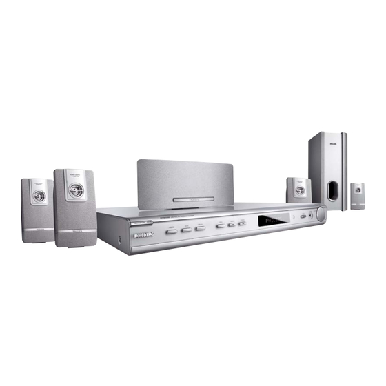
Surround Receiver
Service
Service
Service
Service
Service
Service Manual
©
Copyright 2005 Philips Consumer Electronics B.V. Eindhoven, The Netherlands
All rights reserved. No part of this publication may be reproduced, stored in a retrieval system or
transmitted, in any form or by any means, electronic, mechanical, photocopying, or otherwise
without the prior permission of Philips.
Published by KC-ET0412 Service Audio Printed in The Netherlands Subject to modification
Version 1
TABLE OF CONTENTS
Location of PC Boards ................................................ 1-2
Versions Variation & Package .................................... 1-2
Specifications .............................................................. 1-3
Measurement Setup ................................................... 1-4
Service Aids ................................................................ 1-5
ESD & Safety Instruction ............................................ 1-6
Lead-free solding Information .................................... 1-7
Repair Instructions ......................................................... 2
Disassembly Instructions & Service positions .............. 3
Block & Wiring Diagram ................................................ 4
Key Board ...................................................................... 5
Power Board .................................................................. 6
Tuner Board ................................................................... 7
Main Board .................................................................... 8
Mechanical Exploded View & Parts List ........................ 9
www.nostatech.com
HTR5000/
Page
GB
01/98
3139 785 31080
Advertisement
Table of Contents

Related Manuals for Philips HTR5000


Summary of Contents for Philips HTR5000
- Page 1 Mechanical Exploded View & Parts List ......9 © Copyright 2005 Philips Consumer Electronics B.V. Eindhoven, The Netherlands All rights reserved. No part of this publication may be reproduced, stored in a retrieval system or transmitted, in any form or by any means, electronic, mechanical, photocopying, or otherwise without the prior permission of Philips.
- Page 2 LOCATION OF PCB BOARDS PHONE PCB VOLUME PCB VERSION VARIATION: Type/Versions HTR5000 HTR5000 Features & / 01 / 98 Board in used RDS function Grid Switch Line Cord (Detachable) Line Cord (Fixed) AC Voltage (110V~127V / 220~240V) AC Voltage (220V~240V)
-
Page 3: Specifications
www.nostatech.nl www.nostatech.com SPECIFICATIONS MAIN UNIT Power Supply Rating 220-240V; 50Hz (for / 01) Power Supply Rating 110-127/ 220-240V; 50/60Hz AMPLIFIER SECTION Switchable (for / 98 ) Total Output Power (Home Theater Mode) Power Consumption 180 W 700W Dimensions (w x h x d) 435mm x 53mm x 359mm Total Output Power (1% THD) Weight... - Page 4 www.nostatech.nl www.nostatech.com MEASUREMENT SETUP Tuner FM Bandpass LF Voltmeter 250Hz-15kHz e.g. PM2534 e.g. 7122 707 48001 RF Generator e.g. PM5326 S/N and distortion meter e.g. Sound Technology ST1700B Use a bandpass filter to eliminate hum (50Hz, 100Hz) and disturbance from the pilottone (19kHz, 38kHz). Tuner AM (MW,LW) Bandpass LF Voltmeter...
-
Page 5: Service Aids
www.nostatech.nl www.nostatech.com SERVICE AIDS Service Tools: Universal Torx driver holder .........4822 395 91019 Torx bit T10 150mm ...........4822 395 50456 Torx driver set T6-T20 .........4822 395 50145 Torx driver T10 extended ........4822 395 50423 Compact Disc: SBC426/426A Test disc 5 + 5A ......4822 397 30096 SBC442 Audio Burn-in test disc 1kHz ....4822 397 30155 SBC429 Audio Signals disc .........4822 397 30184 Dolby Pro-logic Test Disc ........4822 395 10216... - Page 6 www.nostatech.nl www.nostatech.com WAARSCHUWING WARNING Alle IC’s en vele andere halfgeleiders zijn All ICs and many other semi-conductors are gevoelig voor electrostatische ontladingen susceptible to electrostatic discharges (ESD). (ESD). Careless handling during repair can reduce life Onzorgvuldig behandelen tijdens reparatie kan drastically.
- Page 7 You will find this and more technical information • Use only lead-free solder alloy Philips SAC305 with within the “magazine”, chapter “workshop news”. order code 0622 149 00106. If lead-free solder-paste is required, please contact the manufacturer of your For additional questions please contact your local solder-equipment.
- Page 8 www.nostatech.nl www.nostatech.com Software Upgrade Procedure 1) Software Update PCB as shown in figure 1. figure 1 2) Plug the updated software IC into PCB as shown in figure 2. figure 2 3) Insert the plug of PCB into bottom of the main unit as shown in figure 3. figure 3 4) Power on, the three LED on the PCB will be on .
- Page 9 www.nostatech.nl www.nostatech.com REPAIR INSTRUCTION...
- Page 10 www.nostatech.nl www.nostatech.com REPAIR INSTRUCTION...
-
Page 11: Disassembly Instructions
www.nostatech.nl www.nostatech.com DISASSEMBLY INSTRUCTIONS 1) Loosen 9 screws and remove the Top Cover by lifting the rear portion upwards before sliding it out towards the rear. - 5 screws on the back - 2 screws each on the left & right side 2) Loosen 7 screws &... - Page 12 www.nostatech.nl www.nostatech.com SERVICE POSITIONS Service position A Service position B...
- Page 13 www.nostatech.nl www.nostatech.com BLOCK DIAGRAM...
- Page 14 www.nostatech.nl www.nostatech.com WIRING DIAGRAM...
- Page 15 www.nostatech.nl www.nostatech.com PT6311 INTERNAL BLOCK DIAGRAM SG1/KS1 SG2/KS2 SG3/KS3 Control SG4/KS4 SG5/KS5 DOUT Serial SG6/KS6 Data Interface SG7/KS7 SG8/KS8 Display Memory Segment Driver / SG9/KS9 Grid Driver / SG10/KS10 Key Scan Output SG11/KS11 SG12/KS12 Timing Generator SG13/KS13 SG14/KS14 General SG16/KS16 Input Key Matrix Memory Register...
- Page 16 www.nostatech.nl www.nostatech.com CIRCUIT DIAGRAM -CONTROL BOARD R229 C201 R235 C202 C203 R236 C203A R236A C204 R980 C205 R981 C207 R982 C208 R983 C209 R984 R985 C210 R986 C211 R987 C217 C218 R988 C219 R989 PT6311 C220 R990 C221 R991 C991 R992 C992 R996...
- Page 17 www.nostatech.nl www.nostatech.com PCB LAYOUT - TOP VIEW D201 XL981 C201 RB202 TA204 D202 ZD201 C203 RB203 TA206 DP201 C203A SN201 TA207 RB2001 C204 TA202 TA209 RB2002 C996 TA203 TA210 PCB LAYOUT - BOTTOM VIEW C202 C211 C991 IC252 R204 R213 R219 R225 R236...
- Page 18 www.nostatech.nl www.nostatech.com POWER BOARD TABLE OF CONTENTS Circuit Diagram ..............6-2 PCB Layout ............... 6-3...
- Page 19 www.nostatech.nl www.nostatech.com CIRCUIT DIAGRAM - POWER BOARD R954 BD901 D906 L-45UH-8A IS 1/4W R04-1-F IS 1/4W 1 OHMRES FUSE JMP-100 100U 35V SCREW-A SCREW-A C955 C104P-100V 470P-1KV R955 JMP18 C965 C104P-100V C901 D907 CN903 IS 1/6W R06-10KM IS 1/6W 10KOHM 1% L952 SCREW-A SCREW-A...
- Page 20 www.nostatech.nl www.nostatech.com PCB LAYOUT - POWER BOARD R970 GT905 BD901 R971 C901 IC901 R972 IC902 C902 R973 IC951 C903 R974 IC952 C904 R975 IC953 C905 R976 JMP01 C906 R977 JMP02 C907 R978 JMP03 C908 R979 JMP04 C909 R980 C910 JMP05 R981 JMP06 C911...
- Page 21 www.nostatech.nl www.nostatech.com TUNER ADJUSTMENT TABLE Waverange Input frequency Input Tuned to Adjust Output Scope/Voltmeter VARICAP ALIGNMENT 108MHz 7.5V ± 1V check 87.5 - 108MHz (50kHz grid) 87.5MHz check 1.4V ± 0.2V 1602KHz 7.2V ± 1V check ± T005 1.1V 0.2V 531KHz 531-1602kHz TUNER BOARD...
- Page 22 www.nostatech.nl www.nostatech.com CIRCUIT DIAGRAM - TUNER BOARD R004 ANT001 A1 C002 R005 C003 R006 R007 C004 C005 R009 C006 R010 C007 R011 C008 R012 C009 R013 R014 R015 C010 C011 R016 C012 R017 ANT001 RF R018 C013 KST-F404 EF450- G1 KST-F404 C014 R019...
- Page 23 www.nostatech.nl www.nostatech.com PCB LAYOUT - TUNER BOARD (TOP) C004 C014 C036 C044 IF001 B2 R005 VD002 A3 C027 CN002 A1 T003 C005 C017 C028 C037 C045 D001 IF002 B3 R024 T004 VR001 A4 C008 C019 C029 C038 C046 D002 IF003 A3 R031 T005 C047...
- Page 24 www.nostatech.nl www.nostatech.com PCB LAYOUT - TUNER BOARD (BOTTOM) C002 C016 C032 C069 Q001 R008 R016 R025 R036 R026 C003 C018 C034 C070 Q004 R009 R017 R037 C006 C035 R010 R018 R027 R038 C020 C071 R001 C007 C021 C072 R002 R011 R019 R028 R039...
- Page 25 www.nostatech.nl www.nostatech.com ES6128 INTERNAL IC DIAGRAM Video ROM/Flash T V Display 4/16 MB Audio DAC Speakers DRAM ES6128 S/PDIF A/V Receiver Vibratto-S EEPROM Audio ADC Microphone In DVD Drive VFD Driver VFD Panel MAIN BOARD IR Remote EN29F040A INTERNAL IC DIAGRAM DQ0 -DQ7 Vc c B l ock Protect Sw itc hes...
- Page 26 www.nostatech.nl www.nostatech.com Voltages: IC210 (ASM809SEURF) IC1010 (WM8772SEDS) PIN NO PIN NO Voltage Voltage PIN NO IC301 (TP5228) Voltage PIN NO Voltage IC1012 (LD1117) PIN NO IC303 & IC304 & IC305 & IC306 & IC307 & IC309 & IC407 & IC408 & IC409 & IC3201 & IC3202 & IC3203 (RC4558D) Voltage PIN NO...
- Page 27 www.nostatech.nl www.nostatech.com CIRCUIT DIAGRAM - TOP LEFT C915 R3001 C923 R3002 C1003 C950 R3004 C951 R3005 C1004 C1005 C952 R3006 R9004 R9005 C1007 C953 R3007 C1022 C954 R3031 R9012 R9035 C1031 C955 R3032 C1032 C956 R3034 R9036 C1033 C957 R3035 R9037 C958 R3036...
- Page 28 www.nostatech.nl www.nostatech.com CIRCUIT DIAGRAM - TOP RIGHT C1001 JR1033 A6 JR1055 A6 C1002 L1003 C1006 C1008 L1013 C1023 L1021 C1024 L1022 L1061 C1027 L1062 C1030 C1034 L1087 C1035 L1101 L1102 C1036 L1103 C1037 C1038 Q905 C1039 Q906 C1040 R1007 R1010 C1041 R1012 C1042...
- Page 29 www.nostatech.nl www.nostatech.com CIRCUIT DIAGRAM - BOTTOM LEFT R366 C1122 C374 Q303 Q304 C1122A C3 C375 R367 C1130 C376 Q305 R368 C1131 C378 Q307 R370 C1132 C388 Q910 R371 C1133 C391 Q911 R372 R375 C1134 C392 C1135 C393 R376 C1136 C394 R377 C1137 C395...
- Page 30 www.nostatech.nl www.nostatech.com CIRCUIT DIAGRAM - BOTTOM RIGHT C5217 D6713 R3703 R537 C5220 R3709 D6714 R566 C5222 D6715 R3712 R567 C5224 R3713 C2001 D903 R580 C2600 C5225 D904 R3716 R581 C5226 R3718 C2601 D905 R582 C2602 C5227 D906 R3721 R583 C2603 C5228 R3722 D907...
- Page 31 www.nostatech.nl www.nostatech.com PCB LAYOUT - TOP VIEW C1008 C1132 C3208 C331 C376 C457 C5229 C9034 CN102 IC5300 C5 L5302 R1021 FB9002 D2 R3067 R3227 R3403 R380 R483 R913 ZD3001 B1 C1134 C1022 C3209 C332 C388 C467 C5234 C9036 CN2001 D1 IC1001 JK302 L5303...
- Page 32 www.nostatech.nl www.nostatech.com PCB LAYOUT - BOTTOM VIEW C1047 C2 C1092 D2 C2609 C4 C321 C337 C5227 B5 C5336 C5 C950 D520 IC7607 D4 Q5203 C3 R1030 D1 R3005 B1 R311 R3722 B5 R5302 C5 C1001 C1 C405 C501 R3251 B3 R337 R3606 C4 R475...
- Page 33 www.nostatech.nl www.nostatech.com EXPLODED DRAWING...
- Page 34 www.nostatech.nl www.nostatech.com MECHANICAL PARTS - ELECTRICAL PARTS LIST - CONTROL PCBA ELECTRICAL PARTS LIST - TUNER PCBA SUBWOOFER ASSEMBLY BREAKDOWN MISCELLANEOUS MISCELLANEOUS MISCELLANEOUS 9965 000 28373 CLOTH FRAME ASS’Y (BACK) 9965 000 29577 CONTROL PCBA DP201 9965 000 17398 VFD HNA-10SS28 CN002 9965 000 25150 CONNECTOR S2B-XH-A 2 PIN...
- Page 35 www.nostatech.nl www.nostatech.com ELECTRICAL PARTS LIST - MAIN PCBA UNIT ELECTRICAL PARTS LIST - POWER PCBA MISCELLANEOUS MISCELLANEOUS CAPCITORS DIODES BD901 9940 000 00931 BRIDGE KBU808 8A 1000V C427 9965 000 23659 COND MYLAR 0.015UF 100V 5% CF1600 9965 000 23595 RES 2P 600KHZ ORANGE BOX D903 9965 000 26949...
- Page 36 9965 000 29612 IC 16 PIN TC4053BFN TOSHIBA D301 9965 000 19409 BAV16W/IN4148W 4822 130 41651 2SC2001L IC3207 9965 000 27092 IC 14 PIN 74HCU04D PHILIPS TS D3015 9965 000 19409 BAV16W/IN4148W Q301 4822 130 41198 2SC945P IC401 9965 000 26921...