
Related Manuals for Philips Video Camera


Summary of Contents for Philips Video Camera
- Page 1 Installation and Operating Manual Fastrax Dome Video Camera for Ceiling and Wall Mounting EDC-141E, EDC-142E, EDC-143E, EDC-142E1, EDC-144E, EDC-142E2...
-
Page 2: Table Of Contents
Contents Introduction ... 3 Features ... 3 Installation and Configuration ... 5 Package Contents... 5 Basic Configuration of Fastrax II Dome Camera System ... 6 2.2.1 Single Multiplexer... 7 2.2.2 Single User with Two Multiplexer ... 8 2.2.3 Two Multiplexer with Slave Keyboard Controller ... 9 2.2.4 Two Multiplexer with Slave Keyboard Controller (method 2) ... -
Page 3: Introduction
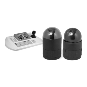
Safety Instructions • Read these safety instructions and the operation manual first before you install and commission the camera. • Keep the manual in a safe place for later reference. • Protect your camera from contamination with water and humidity to prevent it from permanent damage. Never switch the camera on when it gets wet. Have it checked at an authorized service center in this case. - Page 4 Alarm Input (up to 8) <Sensor> Alarm <Siren> Output (up to 4) <Flashing light> up to 32 cameras Figure 1 - Typical System Configuration push Remove window Figure 2 - Assemble bubble ring ass’y Note: It is recommended to remove camera window for improving picture quality when you assemble bubble ring ass’y. up to 255 multiplexer J-box Master keyboard...
-
Page 5: Installation And Configuration
2. Installation and Configuration 2.1 Package Contents The package contains the following: 1x Fastrax II E (Dome Camera) 1x Bubble Ring 1x Instruction Manual (This Document) 3x Assembly Screws for Attaching Fastrax II E 3x Plastic Anchor 1x 10Pin Connector 2x 12Pin Connector CAUTION: Be sure to have caution labels (E version only) on both body and base of the camera. -
Page 6: Basic Configuration Of Fastrax Ii Dome Camera System
2.2 Basic Configuration of Fastrax II Dome Camera System Power 24VAC STP AWG #24 Sensor Alarm input up to 8 Siren Light Alarm output up to 4 J-Box (Back) Up to 128 Dome cameras including 32 alarm mode can be connected at DOME2 port. -
Page 7: Single Multiplexer
2.2.1 Single Multiplexer Power 24VAC AWG #24 Spot Monitor Multiplexer J-Box (Back) Figure 5 - Single Multiplexer Power Power 24VAC 24VAC Main Monitor J-Box (Front) Rear Keyboard controller RS-485 (–) Pin No. 4 RS-485 (+) Pin No. 6... -
Page 8: Single User With Two Multiplexer
2.2.2 Single User with Two Multiplexer Power 24VAC AWG #24 1st Main Monitor 1st Multiplexer J-Box (Back) Keyboard controller Figure 6 - Two Multiplexer Power Power 24VAC 24VAC Spot Monitor RS-485 (–) Pin No. 4 RS-485 (+) Pin No. 6 J-Box (Front) Spot output of the first multiplexer to be connected to 16... -
Page 9: Two Multiplexer With Slave Keyboard Controller
2.2.3 Two Multiplexer with Slave Keyboard Controller Power 24VAC AWG #24 1st Main Monitor 1st Multiplexer J-Box (Back) Keyboard controller Master Figure 7 - Two Multiplexer with Slave Keyboard Controller Power Power 24VAC 24VAC Spot Monitor Spot Monitor for Slave K/B for Master K/B RS-485 (–) Pin No. -
Page 10: Two Multiplexer With Slave Keyboard Controller (Method 2)
2.2.4 Two Multiplexer with Slave Keyboard Controller (method 2) Power 24VAC AWG #24 1st Main Monitor 1st Multiplexer J-Box (Back) Keyboard controller Master Figure 8 - Two Multiplexer with Slave Keyboard Controller (method 2) Power Power 24VAC 24VAC Spot Monitor Spot Monitor for Slave K/B for Master K/B... -
Page 11: Setting Unit For Termination
Termination switches Addresses (ID) and protocol selection switches Figure 9 - Layout of Switches 2.3 Setting Unit for Termination The device which is connected at end of line, whether it is a dome camera or keyboard controller, must have the cable for communication terminated by setting the appropriate DIP switch. -
Page 12: Setting Address (Id) Of Dome Camera
Figure 11 - Termination Diagram 2.4 Setting Address (ID) of Dome Camera To prevent damage, each dome camera must have a unique address (ID). When installing multiple dome cameras using a multiplexer, it is suggested that the dome camera address matches the multiplexer port number. If you wan to set the address more than 999, you should connect the service provider. -
Page 13: Setting Protocol Of Dome Camera
Enable Disable S4-2 NTSC S4-3 Endless S4-4 RS-422 RS-485 S5-1 S5-2 S5-3 Fastrax, Pelco D&P, Dynacolor, Ernitec & Philips G3 Protocol (Default) Sensormatic RS-422 Vicon Protocol S5-4 S6-1 S6-2 9600 bps (Default) S6-3 S6-4 Default cameras (Default) Function Alarm NTSC/PAL... -
Page 14: Connection
2.6 Connection • Connecting to the RS-485/-422 NOTE: Should you experience any control problems when using the Pelco-protocol, connect the ground plate (GND) to the control component. The dome camera can be controlled remotely by an external device or control system, such as a control keyboard, using RS-485 half-duplex, RS-422 duplex or simplex serial communications signals. -
Page 15: Program And Operation
3. Program and Operation 3.1 Selecting Dome Camera Before you program or operate a dome camera, you must select the dome camera by pressing the dome camera No. + CAM successively. Example: Pressing 1, 0 and CAM key sequentially will select dome camera 10. The selected dome camera ID will be displayed on the LCD monitor of the keyboard controller. -
Page 16: Auto Scan
3.4 Auto Scan (First Item of the Main menu / Shortcut: Scan) The Auto scan supports up to 8 programmed angles at user-programmable speeds. Follow these steps to program Auto Scan: SPEED (MODE): NORMAL1~NOMAL9, SLOW VECTOR, FAST VECTOR NORMAL1 (SLOWER) <––> NORMAL9 ( FASTER) SLOW VECTOR, FAST VECTOR: Move from start point to end point including tilt and zoom simultaneously and linearly. -
Page 17: Preset
3.5 Preset (Second Item of the Main menu / Shortcut: Prst) If you need to view specific locations routinely, you should program presets. A preset is a programmed video scene with automatic pan, tilt, zoom, focus and iris settings. Once programmed, entering the number and pressing a Preset button on your controller automatically calls up the preset. In addition, presets may be assigned to alarm actions or as the „home”... -
Page 18: Shortcut Of Preset Program
3.6 Shortcut of Preset Program Select a view to be stored (direction of the camera, zoom and focus), then press No. (1 to 240), and then press Pgm, Prst subsequently. The current view will be stored to the selected preset number if position is empty. If selected preset number is not empty, „PRESET EXISTING” message will be displayed on the monitor and ask to overwrite. -
Page 19: Pattern
4. To add a stored preset as a Tour, twist the Zoom handle or press Zoom Key (Programmed preset will scroll). To remove a stored preset from the Tour, press the Home key, blank position mark (===) will be displayed. You can overwrite the programmed position. 5. -
Page 20: Alarm
3.9 Alarm (This menu shows on only specific model, Fifth Item of Main menu) NO : Alarm input number PRI : Lower No. has higher priority, Equal priority alarms will be serviced repeatedly. PRS : Stored preset number to be called by alarm. IN : NO/NC - normally open /Closed OFF - ignore OUT :... -
Page 21: Privacy Zone
Pages can be scrolled through by pushing the Joystick to the left or right on the first or last column of the menu. Pushing the Joystick to left on the „NO” column (01 ~ 08) of the menu to scroll to the previous page. Push the Joystick to right on the „END” column to go to the next page. 1. -
Page 22: Camera
3.12 Camera (Eighth Item of Main menu) NOTE: The menu features will vary depending on the camera module installed in your dome camera. SHARPNESS The higher the value, the more edges in the picture will be enhanced. EDC-141E, EDC-142E, EDC-144E: 0~15 EDC-143E: 0~63 EDC-142E1, EDC-142E2: 0 ~ 20 BACK LIGHT... -
Page 23: Wb (White Balance) Control
• WB (white balance) CONTROL EDC-141E EDC-142E EDC-144E MODE : MANUAL / AUTO / INDOOR / OUTDOOR / ONE PUSH / ATW RGAIN : 0 ~ 255 BGAIN : 0 ~ 255 Use the ATW mode for normal use. RGAIN / BGAIN modes are controllable only in MANUAL Mode. Push the Joystick to the right or left to change. -
Page 24: Ae Control
• AE CONTROL EDC-141E EDC-142E EDC-144E MODE FULL AUTO / MANUAL / IRIS PRIO / SHUTTER PRIO / BRIGHT SLOW SHUTTER AUTO / MANUAL – AUTO effects only FULL AUTO mode IRIS : CLOSE / F22 / F19 / F16 / F14 / F11 / F9.6 / F8.0 / F6.8 / F5.6 / F4.8 / F4.0 / F3.4 / F2.8 / F2.4 / F2.0 / F1.6 / F1.4 GAIN : 0 / 2 / 4 / 6 ... -
Page 25: Line Lock Control
EDC-142E1 EDC-142E2 MODE : FULL AUTO / SHUTTER PRIO / IRIS PRIO / AGC / MANUAL SLOW SHUTTER : AUTO / OFF, ON (MANUAL, SHUTTER PRIO Mode) IRIS : CLOSE / F1,6 / F2,0 / F2,8 / F4,0 / F5,6 / F8,0 / F11 / F16 / F22 / F32 GAIN : OFF, 2, 4, 6, 8, 10, 12, 14, 16, 18, 20dB BRIGHT :... -
Page 26: Dome Setup
3.13 Dome Setup (Ninth Item of Main menu) • LANGUAGE SETUP LANGUAGE : Select the language you want. * This setup displays more than 3.0 of the ROM version. • HOME FUNCTION SETUP After a dome control menu item has been selected, follow the directions below to set the function. HOME FUNCTION : NONE / PRESET / TOUR / PATTERN / AUTO SCAN FUNCTION NUMBER :... -
Page 27: Osd Display Setup
• OSD DISPLAY CAMERA TITLE : 8 CHARACTER CAN BE SET VIEW DIRECTION : ON / OFF DOME OSD DISPLAY : ON / OFF AREA DISPLAY : ON / OFF • VIEW DIRECTION „ON” sets current direction as N(North) and the coordinate angle to 000. „OFF” hides the directional title. Every 90 degrees of clockwise rotation will change the title to E(East), S(South), W(West). -
Page 28: Tilt Over Angle
• PANNING RANGE When the dome camera is installed near wall, panning range could be programmed by user. • FLIP Allows the dome camera to automatically turn 180 degrees when the camera tilts to its lower position. When camera reaches floor alone moving object, it will stop. Release the Joystick handle instantly and then pull down to run flip fucntion. The speed of following object will be same speed as previous. -
Page 29: Dome Reset
• DOME RESET This feature is used to re-calibrate the orientation of a selected dome camera. Origin offset value is not affected by this function. (Offset is still valid after origin set) • SYSTEM INFORMATION A Dome camera’s Setup menu provides essential information about the dome camera when service is required. When you view this screen, you can determine the camera type, ROM version. -
Page 30: Glossary
5. Glossary Alarm Actions The assigned responses for the dome camera when inputs change from normal to abnormal states. The dome may run a Preset, Pattern, or have no assigned action for each of the four dome inputs. The dome may also send alarm states to the host controller for processing. -
Page 31: Short-Cut Key
6. Short Cut Key Short Cut Key Function PRST Pop up preset setup menu TOUR Pop up guard Tour setup menu PTRN Pop up Pattern setup menu SCAN Pop up Auto Scan setup menu NO.+ PGM + PRST Store the current view at the selected number NO.+ PGM + TOUR Pop up tour setup menu at the selected number NO.+ PGM + SCAN... -
Page 32: Specifications
7. Specifications Model EDC-142E 74081 Imager Sensitivity 1.0Lux at F1.4 (0.75Lux at F1.2) Horizontal resolution Adresses Dynamic range (WDR) Speed range at manual control (pan) 0.1° to 90°/sec., Turbo: 360°/sec. (Proportional to the zoom position) Speed range at manual control (tilt) 0.1°... - Page 33 RS-422/RS-485, 9600Baud, 999 camera ID adresses selectable. Besides the keyboard control via the eneo EDC-KBD(M) series, the control via matrix switchers and keyboards from Pelco (D+P protocol), Ernitec, Philips G3, Sensormatic RS-422, (back channel via RS-422 is not activated), Vicon and Dynacolor is available.
-
Page 34: Dimensional Drawings
Accessories EDP No. Description 74088 System Keyboard with 3-axis Joystick, 12VDC/230VAC 74092 System Keyboard with Joystick, 5” Monitor, 12VDC/230VAC 75201 Matrix, Multiplexer and Telemetry Keyboard with Joystick, RS-485 Control 74057 Flush Mount Dome Housing, Smoked Bubble, 4.9” 74078 Pendant Mount Outdoor Dome Housing, Tinted Bubble 6.8”, 24VAC 74077 Pendant Mount Indoor Dome Housing, Clear Bubble 6.8”, 24VAC 74076...