Asus Strix Z270I Gaming User Manual
Hide thumbs
Also See for Strix Z270I Gaming:
- Quick start manual (2 pages) ,
- Quick start manual (2 pages)
Table of Contents
Advertisement
Advertisement
Table of Contents

Related Manuals for Asus Strix Z270I Gaming


Summary of Contents for Asus Strix Z270I Gaming
- Page 1 STRIX Z270I GAMING...
- Page 2 Product warranty or service will not be extended if: (1) the product is repaired, modified or altered, unless such repair, modification of alteration is authorized in writing by ASUS; or (2) the serial number of the product is defaced or missing.
-
Page 3: Table Of Contents
Contents Safety information ...................... vi About this guide ......................vii STRIX Z270I GAMING specifications summary ............ix Package contents ..................... xiii Installation tools and components ................. xiv Chapter 1: Product Introduction Motherboard overview ................1-1 1.1.1 Before you proceed ..............1-1 1.1.2... - Page 4 3.6.11 USB Configuration ..............3-19 Monitor menu ................... 3-19 Boot menu ....................3-19 Tool menu ....................3-21 3.9.1 ASUS EZ Flash 3 Utility ............3-21 3.9.2 Secure Erase ................3-21 3.9.3 ASUS Overclocking Profile ............3-22 3.9.4 ASUS SPD Information ............. 3-22 3.9.5...
- Page 5 Rapid Storage Technology in UEFI BIOS ......4-2 ® 4.1.4 Intel Rapid Storage Technology Option ROM utility ....4-6 ® Creating a RAID driver disk..............4-10 4.2.1 Creating a RAID driver disk in Windows ......... 4-10 ® Appendix Notices ........................A-1 ASUS contact information ..................A-6...
-
Page 6: Safety Information
Safety information Electrical safety • To prevent electrical shock hazard, disconnect the power cable from the electrical outlet before relocating the system. • When adding or removing devices to or from the system, ensure that the power cables for the devices are unplugged before the signal cables are connected. If possible, disconnect all power cables from the existing system before you add a device. -
Page 7: About This Guide
Refer to the following sources for additional information and for product and software updates. ASUS website The ASUS website (www.asus.com) provides updated information on ASUS hardware and software products. Optional documentation Your product package may include optional documentation, such as warranty flyers, that may have been added by your dealer. -
Page 8: Conventions Used In This Guide
Conventions used in this guide To ensure that you perform certain tasks properly, take note of the following symbols used throughout this manual. DANGER/WARNING: Information to prevent injury to yourself when trying to complete a task. CAUTION: Information to prevent damage to the components when trying to complete a task. -
Page 9: Strix Z270I Gaming Specifications Summary
Extreme Memory Profile (XMP) ® * Hyper DIMM support is subject to the physical characteristics of individual CPUs. ** Refer to www.asus.com for the lastest Memory QVL(Qualified Vendors List). Expansion slots 1 x PCIe 3.0 x16 slot Integrated Graphics Processor- Intel HD Graphics support ®... - Page 10 Ports 4 x USB 2.0 ports 1 x Optical S/PDIF out 5 x Audio jacks 1 x ASUS Wi-Fi module (Wi-Fi 802.11 a/b/g/n/ac and Bluetooth v4.1) Intel Z270 Chipset with with RAID 0, 1, 5, 10 and Intel Rapid Storage ®...
- Page 11 STRIX Z270I GAMING specifications summary RAMCache II ROG GameFirst IV* ROG Exclusive ROG Overwolf Features ROG Clone Drive * ROG GameFirst IV is only available for Windows 10/8.1 64-bit. ® Performance Optimization 5-Way Optimization - Whole system optimization with a single click! Perfectly consolidates better CPU performance, power saving, digital power control, system cooling and app usages.
- Page 12 7 32/64-bit are only supported when using ® ® 6th Generation Intel Processors. ® Form factor Mini ITX Form Factor, 6.7” x 6.7” (17cm x 17cm) Specifications are subject to change without notice. Please refer to the ASUS website for the latest specifications.
-
Page 13: Package Contents
1 x ROG cable label Accessories 2 x M.2 screw packages 2 x M.2 2242 Mounting Kit 1 x CPU installation tool 1 x ASUS 2x2 dual band Wi-Fi moving antennas (Wi-Fi 802.11a/b/g/n/ac compliant) Application drive ROG motherboard support DVD Documentation User Guide If any of the above items is damaged or missing, contact your retailer. -
Page 14: Installation Tools And Components
Installation tools and components Intel 1151 CPU ® Intel 1151 compatible CPU Fan ® Phillips (cross) screwdriver SATA hard disk drive PC chassis 1 bag of screws DIMM Power supply unit SATA optical disc drive (optional) Graphics card The tools and components listed above are not included in the motherboard package. -
Page 15: Chapter 1: Product Introduction
Unplug the power cord from the wall socket before touching any component. • Before handling components, use a grounded wrist strap or touch a safely grounded object or a metal object, such as the power supply case, to avoid damaging them due to static electricity. • Hold components by the edges to avoid touching the ICs on them. • Whenever you uninstall any component, place it on a grounded antistatic pad or in the bag that came with the component. • Before you install or remove any component, ensure that the ATX power supply is switched off or the power cord is detached from the power supply. Failure to do so may cause severe damage to the motherboard, peripherals, or components. ASUS STRIX Z270I GAMING... -
Page 16: Motherboard Layout
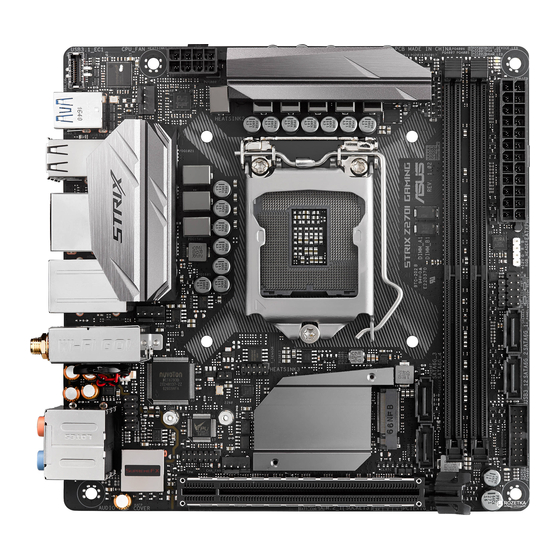
1.1.2 Motherboard layout 17.0cm(6.7in) BOOT_DEVICE_LED USB3.1_EC1 VGA_LED DRAM_LED CPU_LED EATX12V RGBLED DIGI USB3_5 +VRM USB3_C6 CPU_FAN USB7_10 HDMI LGA1151 LAN_USB3_34 Intel ® (Bottom) I219V AIO_PUMP M.2(WIFI) 128Mb BIOS BATT_CON Super T_SENSOR Intel ® Z270 AAFP 2260 2280 AUDIO CLRTC CHA_FAN 1220 PCIEX16_1 PCIE SATA IRST... -
Page 17: Layout Contents
7. DDR4 DIMM slots 8. POST State LEDs 1-10 9. RGB LED 1-10 10, RGB header (4-pin RGB_HEADER) 11. System panel connector (10-1 pin F_PANEL) 1-17 12. Speaker connector (4-pin SPEAKER) 1-16 13. Intel Serial ATA 6 Gb/s connectors (7-pin SATA6G_1~4) 1-11 ® 14. USB 3.0 connector (20-1 pin USB3_12) 1-12 15. Clear RTC RAM (2-pin CLRTC) 16. TPM connector (14-1 pin TPM) 1-13 17. Front panel audio connector (10-1 pin AAFP) 1-11 18. RTC Battery header (2-pin BATT_CON) 19. M.2 sockets (M.2_2) 1-14 ASUS STRIX Z270I GAMING... -
Page 18: Central Processing Unit (Cpu)
1.1.3 Central Processing Unit (CPU) The motherboard comes with a surface mount LGA1151 socket designed for the 7th / 6th Generation Intel Core™ i7 / Intel Core™ i5 / Intel Core™ i3, Pentium , and Celeron ® ® ® ® ® processors. STRIX Z270I GAMING CPU socket LGA1151 • Ensure that all power cables are unplugged before installing the CPU. • Upon purchase of the motherboard, ensure that the PnP cap is on the socket and the socket contacts are not bent. Contact your retailer immediately if the PnP cap is missing, or if you see any damage to the PnP cap/socket contacts/motherboard components. ASUS will shoulder the cost of repair only if the damage is shipment/ transit-related. • Keep the cap after installing the motherboard. ASUS will process Return Merchandise Authorization (RMA) requests only if the motherboard comes with the cap on the LGA1151 socket. • The product warranty does not cover damage to the socket contacts resulting from incorrect CPU installation/removal, or misplacement/loss/incorrect removal of the PnP cap. Chapter 1: Product Introduction... -
Page 19: System Memory
1.1.4 System memory The motherboard comes with two DDR4 (Double Data Rate 4) Dual Inline Memory Modules (DIMM) slots. A DDR4 module is notched differently from a DDR, DDR2, or DDR3 module. DO NOT install a DDR, DDR2, or DDR3 memory module to the DDR4 slot. STRIX Z270I GAMING 288-pin DDR4 DIMM sockets Recommended memory configurations ASUS STRIX Z270I GAMING... -
Page 20: Memory Configurations
For more details, refer to the Microsoft support site at http://support.microsoft. ® com/kb/929605/en-us. • The design of the DIMM fan may vary. Ensure that the DIMM fan fits to the motherboard • The default memory operation frequency is dependent on its Serial Presence Detect (SPD), which is the standard way of accessing information from a memory module. Under the default state, some memory modules for overclocking may operate at a lower frequency than the vendor-marked value. • For system stability, use a more efficient memory cooling system to support a full memory load (2 DIMMs) or overclocking condition. • Memory modules with memory frequency higher than 2133MHz and their corresponding timing or the loaded XMP profile is not the JEDEC memory standard. The stability and compatibility of the memory modules depend on the CPU’s capabilities and other installed devices. • Always install the DIMMS with the same CAS Latency. For an optimum compatibility, we recommend that you install memory modules of the same version or data code (D/C) from the same vendor. Check with the vendor to get the correct memory modules. • ASUS exclusively provides hyper DIMM support function. • Hyper DIMM support is subject to the physical characteristics of individual CPUs. Load the X.M.P. or D.O.C.P. settings in the BIOS for the hyper DIMM support. • Visit the ASUS website for the latest QVL. Chapter 1: Product Introduction... -
Page 21: Expansion Slots
– M.2_1 shared – – – M.2 WIFI – – – shared M.2_2 shared – – – PCIEX16_1 shared – – – XHCI shared – – – SATA shared – – – HD Audio shared – – – ASUS STRIX Z270I GAMING... -
Page 22: Headers
1.1.6 Headers Clear RTC RAM (2-pin CLRTC) This header allows you to clear the CMOS RTC RAM data of the system setup information such as date, time, and system passwords. CLRTC PIN 1 STRIX Z270I GAMING Clear RTC RAM To erase the RTC RAM: Turn OFF the computer and unplug the power cord. Use a metal object such as a screwdriver to short the two pins. Plug the power cord and turn ON the computer. Hold down the <Del> key during the boot process and enter BIOS setup to re-enter data. If the steps above do not help, remove the onboard battery and short the two pins again to clear the CMOS RTC RAM data. After clearing the CMOS, reinstall the battery. RTC Battery header (2-pin BATT_CON) This header is for the lithium CMOS battery. BATT_CON PIN 1 STRIX Z270I GAMING Battery header... - Page 23 RGB header (4-pin RGB_HEADER) This header is for RGB LED strips. RGB_HEADER +12V PIN 1 STRIX Z270I GAMING RGB header The RGB header supports 5050 RGB multi-color LED strips (12V/G/R/B), with a maximum power rating of 2A (12V), and no longer than 2 m. Before you install or remove any component, ensure that the ATX power supply is switched off or the power cord is detached from the power supply. Failure to do so may cause severe damage to the motherboard, peripherals, or components. • Actual lighting and color will vary with LED strip. • If your LED strip does not light up, check if the RGB LED extension cable and the RGB LED strip is connected in the correct orientation, and the 12V connector is aligned with the 12V header on the motherboard. • The LED strip will only light up when the system is operating. • The LED strips are purchased separately. ASUS STRIX Z270I GAMING...
-
Page 24: Onboard Leds
DRAM_LED CPU_LED STRIX Z270I GAMING CPU/DRAM/ BOOT_DEVICE/VGA LED RGB LED The RGB LED lighting control provides several lighting schemes, which allow you to customize your favorite LED effect. You can set your favorite LED effect to cast a stunning multi-color glow across your build, change shades to indicate CPU temperature, pulsate in time to the beat of your music, or set your favorite color for each pair of LEDs. RGB1 RGB2 RGB3 RGB4 RGB5 RGB6 RGB LED(Bottom) RGB7 RGB8 RGB9 RGB10 RGB11 RGB12 STRIX Z270I GAMING RGB LED Lighting Chapter 1: Product Introduction 1-10... -
Page 25: Internal Connectors
SENSE2_RETUR SENSE_SEND PORT2 R SENSE1_RETUR PORT1 R PORT1 L AGND PIN 1 HD-audio-compliant pin definition STRIX Z270I GAMING Analog front panel connector We recommend that you connect a high-definition front panel audio module to this connector to avail of the motherboard’s high-definition audio capability. Intel Serial ATA 6 Gb/s connectors (7-pin SATA 6G_1~4) ® These connectors connect to Serial ATA 6 Gb/s hard disk drives via Serial ATA 6 Gb/s signal cables. If you installed Serial ATA hard disk drives, you can create a RAID 0, 1, 5, and 10 configuration with the Intel Rapid Storage Technology through the onboard Intel ®... - Page 26 USB3+5V USB3+5V IntA_P1_SSRX- IntA_P2_SSRX- IntA_P1_SSRX+ IntA_P2_SSRX+ IntA_P1_SSTX- IntA_P2_SSTX- IntA_P1_SSTX+ IntA_P2_SSTX+ IntA_P1_D- IntA_P2_D- IntA_P1_D+ IntA_P2_D+ STRIX Z270I GAMING USB3.0 front panel connectors The USB 3.0 module is purchased separately. USB 3.1 front panel connector (USB3.1_EC1) This connector allows you to connect a USB 3.1 module for additional USB 3.1 ports. The latest USB 3.1 connectivity provides data transfer speeds of up to 10 Gbps. The next-generation standard is completely backward-compatible with your existing USB devices. USB3.1_EC1 VBUS SBU2 TX2+ SBU1 TX2- VBUS RX2+...
- Page 27 TPM connector (14-1 pin TPM) This connector supports a Trusted Platform Module (TPM) system, which securely stores keys, digital certificates, passwords and data. A TPM system also helps enhance network security, protect digital identities, and ensures platform integrity. PIN 1 STRIX Z270I GAMING TPM connector The TPM module is purchased separately. Thermal sensor connector (2-pin T_SENSOR) This connector is for the thermistor cable that monitors the temperature of the devices and the critical components inside the motherboard. Connect the thermistor cable and place the sensor on the device or the motherboard’s component to detect its temperature. T_SENSOR PIN 1 SENSOR IN STRIX Z270I GAMING T_SENSOR connector ASUS STRIX Z270I GAMING 1-13...
- Page 28 M.2 sockets (M.2_1~2) These sockets allow you to install M.2 SSD modules. M.2_1(SOCKET3) M.2_2(SOCKET3) 2280 2260 (Bottom) STRIX Z270I GAMING M.2(SOCKET3) • M.2_1 socket supports PCIe 3.0 x4 and SATA M Key design and type 2242/2260/ 2280 SATA storage devices. • M.2_2 socket supports PCIe 3.0 x4 M Key design and type 2242/2260/2280 PCIe storage devices. • These sockets support IRST (Intel Rapid Storage Technology). ® • The M.2 SSD module is purchased separately. • For a 2242 storage device, use the bundled 2242 mounting kit. To install a 2242 M.2 SSD module: Align the bigger hole on the mounting kit with the 2260 standoff and secure it with a screw.
- Page 29 These are not jumpers! Do not place jumper caps on the fan connectors! • Ensure that the CPU fan cable is securely installed to the CPU fan connector. CPU_FAN CPU FAN PWR CPU FAN IN CPU FAN PWM AIO_PUMP CHA_FAN STRIX Z270I GAMING Fan connectors • The CPU_FAN connector supports the CPU fan of maximum 1A (12 W) fan power. • Connect the fan of your water cooling kit to the AIO_PUMP connector. ASUS STRIX Z270I GAMING 1-15...
- Page 30 +5 Volts Power OK -5 Volts PIN 1 +5 Volts +5 Volts PSON# -12 Volts +3 Volts +3 Volts +3 Volts PIN 1 STRIX Z270I GAMING ATX power connectors • For a fully configured system, we recommend that you use a power supply unit (PSU) that complies with ATX 12 V Specification 2.0 (or later version) and provides a minimum power of 350 W. • DO NOT forget to connect the 8-pin EATX12V power plug. Otherwise, the system will not boot. • We recommend that you use a PSU with a higher power output when configuring a system with more power-consuming devices. The system may become unstable or may not boot up if the power is inadequate.
- Page 31 System panel connector (10-1 pin PANEL) This connector supports several chassis-mounted functions. F_PANEL +PWR LED PWR BTN PIN 1 +HDD_LED RESET STRIX Z270I GAMING System panel connector • System power LED (2-pin PWR_LED) This 2-pin connector is for the system power LED. Connect the chassis power LED cable to this connector. The system power LED lights up when you turn on the system power, and blinks when the system is in sleep mode. • Hard disk drive activity LED (2-pin HDD_LED) This 2-pin connector is for the HDD Activity LED. Connect the HDD Activity LED cable to this connector. The HDD LED lights up or flashes when data is read from or written...
- Page 32 Chapter 1: Product Introduction 1-18...
-
Page 33: Chapter 2: Basic Installation
2.1.1 Motherboard installation Install the ASUS Q-Shield to the chassis rear I/O panel. Place the motherboard into the chassis, ensuring that its rear I/O ports are aligned to the chassis’ rear I/O panel. - Page 34 Place four (4) screws into the holes indicated by circles to secure the motherboard to the chassis. DO NOT overtighten the screws! Doing so can damage the motherboard. Chapter 2: Basic Installation...
-
Page 35: Cpu Installation
Ensure that you install the correct CPU designed for LGA1151 socket only. DO NOT install a CPU designed for LGA1155 and LGA1156 sockets on the LGA1151 socket. Top of CPU Bottom of CPU Bottom of CPU ASUS STRIX Z270I GAMING... - Page 36 Top of CPU • The CPU Installation Tool is only compatible on ASUS motherboards with a Intel ® LGA1151 socket. • Ensure that the CPU is firmly clicked into place before installing it onto the CPU socket on the motherboard. • Use the CPU Installation Tool for installing the CPU only. DO NOT damage or bend the CPU Installation Tool. • Always firmly hold both sides of the CPU Installation Tool when installing, removing, or picking up the CPU Installation Tool. • Ensure to use a soft stable surface when installing the CPU to the CPU Installation Tool to prevent CPU damage. • ASUS will not cover damages resulting from incorrect CPU installation/removal, incorrect CPU orientation/placement, or other damages resulting from negligence by the user.
-
Page 37: Cpu Heatsink And Fan Assembly Installation
2.1.3 CPU heatsink and fan assembly installation Apply the Thermal Interface Material to the CPU heatsink and CPU before you install the heatsink and fan, if necessary. To install the CPU heatsink and fan assembly ASUS STRIX Z270I GAMING... - Page 38 To uninstall the CPU heatsink and fan assembly Chapter 2: Basic Installation...
-
Page 39: Dimm Installation
2.1.4 DIMM installation To remove a DIMM ASUS STRIX Z270I GAMING... -
Page 40: Atx Power Connection
2.1.5 ATX power connection Ensure to connect the 8-pin power plug. Chapter 2: Basic Installation... -
Page 41: Sata Device Connection
2.1.6 SATA device connection ASUS STRIX Z270I GAMING... -
Page 42: Front I/O Connector
2.1.7 Front I/O connector To install front panel connector To install USB 3.1 connector USB 3.1 To install USB 3.0 connector To install front panel audio connector USB 3.0 AAFP 2.1.8 Expansion card installation To install PCIe x16 cards Chapter 2: Basic Installation 2-10... -
Page 43: Installation
2.1.9 M.2 installation The M.2 SSD is purchased separately. ASUS STRIX Z270I GAMING 2-11... -
Page 44: Wi-Fi Antenna Installation
2.1.10 Wi-Fi antenna installation Installing the ASUS 2x2 dual band W-Fi antenna Connect the bundled ASUS 2x2 dual band Wi-Fi antenna connector to the Wi-Fi ports at the back of the chassis. IO Shield • Ensure that the ASUS 2x2 dual band Wi-Fi antenna is securely installed to the Wi-Fi ports. • Ensure that the antenna is at least 20 cm away from all persons. The illustration above is for reference only. The I/O port layout may vary with models, but the Wi-Fi antenna installation procedure is the same for all models. -
Page 45: Motherboard Rear And Audio Connections
* and ** : Refer to the tables on the next page for LAN port LEDs and audio port definitions. • The plugged USB 3.0 device may run on xHCI mode or EHCI mode, depending on the operating system’s setting. • USB 3.0 devices can only be used as data storage only. • We strongly recommend that you connect USB 3.0 devices to USB 3.0 ports for faster and better performance for your USB 3.0 devices. ASUS STRIX Z270I GAMING 2-13... - Page 46 * LAN ports LED indications Activity Link LED Speed LED Status Description Status Description ACT/LINK SPEED No link 10 Mbps connection Orange Linked Orange 100 Mbps connection Orange (Blinking) Data activity Green 1 Gbps connection Orange (Blinking Ready to wake up LAN port then steady) from S5 mode...
-
Page 47: Audio I/O Connections
2.2.2 Audio I/O connections Audio I/O ports Connect to Headphone and Mic Connect to Stereo Speakers Connect to 2 channel Speakers ASUS STRIX Z270I GAMING 2-15... - Page 48 Connect to 4 channel Speakers Connect to 6 channel Speakers If you are using Windows 8.1/10 platform, use only the light blue audio port for Side ® Speaker Out in a 6-channel configuration. Chapter 2: Basic Installation 2-16...
-
Page 49: Starting Up For The First Time
If you do not see anything within 30 seconds from the time you turned on the power, the system may have failed a power-on test. Check the jumper settings and connections or call your retailer for assistance. ASUS STRIX Z270I GAMING 2-17... -
Page 50: Turning Off The Computer
BIOS Beep Description One short beep VGA detected Quick boot set to disabled No keyboard detected One continuous beep followed by two No memory detected short beeps then a pause (repeated) One continuous beep followed by three No VGA detected short beeps One continuous beep followed by four Hardware component failure... -
Page 51: Chapter 3: Bios Setup
BIOS Setup Knowing BIOS The new ASUS UEFI BIOS is a Unified Extensible Interface that complies with UEFI architecture, offering a user-friendly interface that goes beyond the traditional keyboard- only BIOS controls to enable a more flexible and convenient mouse input. You can easily navigate the new UEFI BIOS with the same smoothness as your operating system. -
Page 52: Bios Setup Program
BIOS setup program Use the BIOS Setup to update the BIOS or configure its parameters. The BIOS screen include navigation keys and brief onscreen help to guide you in using the BIOS Setup program. Entering BIOS at startup To enter BIOS Setup at startup, press <Delete> or <F2> during the Power-On Self Test (POST). -
Page 53: Ez Mode
Click to go to Advanced mode Loads optimized Search on the FAQ default settings Click to display boot devices Selects the boot device priority The boot device options vary depending on the devices you installed to the system. ASUS STRIX Z270I GAMING... -
Page 54: Advanced Mode
3.2.2 Advanced Mode The Advanced Mode provides advanced options for experienced end-users to configure the BIOS settings. The figure below shows an example of the Advanced Mode. Refer to the following sections for the detailed configurations. To switch from EZ Mode to Advanced Mode, click Advanced Mode(F7) or press the <F7> hotkey. -
Page 55: Menu Bar
This button above the menu bar allows you to view and tweak the overclocking settings of your system. It also allows you to change the motherboard’s SATA mode from AHCI to RAID mode. Refer to section 3.2.4 EZ Tuning Wizard for more information. ASUS STRIX Z270I GAMING... -
Page 56: Hot Keys
Move your mouse over this button to show a QR code, scan this QR code on your mobile device to connect to the BIOS FAQ web page of the ASUS support website. You can also scan the following QR code: Hot keys This button above the menu bar contains the navigation keys for the BIOS setup program. -
Page 57: Qfan Control
Click to activate DC Mode configured PWM Mode Select a profile to Click to apply the fan setting apply to your fans Click to undo the Click to go back to main menu changes Select to manually configure your fans ASUS STRIX Z270I GAMING... - Page 58 Configuring fans manually Select Manual from the list of profiles to manually configure your fans’ operating speed. Speed points Select to manually configure your fans To configure your fans: Select the fan that you want to configure and to view its current status. Click and drag the speed points to adjust the fans’...
-
Page 59: Ez Tuning Wizard
To start OC Tuning: Press <F11> on your keyboard or click from the BIOS screen to open EZ Tuning Wizard screen. Click OC then click Next. Select a PC scenario Daily Computing or Gaming/Media Editing, then click Next. ASUS STRIX Z270I GAMING... -
Page 60: Creating Raid
Select a Main Cooling System BOX cooler, Tower cooler, Water cooler, or I’m not sure, then click Next. After selecting the Main Cooling System, click Next then click Yes to start the OC Tuning. Creating RAID To create RAID: Press <F11> on your keyboard or click from the BIOS screen to open EZ Tuning Wizard screen. - Page 61 After selecting the type of RAID, click Next then click Yes to continue the RAID setup. After the RAID setup is done, click Yes to exit the setup then click OK to reset your system. ASUS STRIX Z270I GAMING 3-11...
-
Page 62: My Favorites
My Favorites My Favorites is your personal space where you can easily save and access your favorite BIOS items. My Favorites comes with several performance, power saving, and fast boot related items by default. You can personalize this screen by adding or removing items. Chapter 3: BIOS Setup 3-12... - Page 63 Configuration items such as Memory SPD Information, system time and date. Click Exit (ESC) or press <Esc> key to close Setup Tree Map screen. Go to My Favorites menu to view the saved BIOS items. ASUS STRIX Z270I GAMING 3-13...
-
Page 64: Main Menu
Main menu The Main menu screen appears when you enter the Advanced Mode of the BIOS Setup program. The Main menu provides you an overview of the basic system information, and allows you to set the system date, time, language, and security settings. Security The Security menu items allow you to change the system security settings. -
Page 65: Cpu Core Ratio
CPU permanently. ASUS MultiCore Enhancement [Auto] This item allows you to maximize the oveclocking performance optimized by ASUS core ratio settings. [Disabled] This item allows you to set to default core ratio settings. CPU Core Ratio This item allows you to set the CPU core ratio limit per core or synchronize automatically to all cores. -
Page 66: Advanced Menu
Internal CPU Power Management The subitems in this menu allow you to set the CPU ratio and their features. Intel(R) SpeedStep(tm) [Auto] This item allows the operating system to dynamically adjust the processor voltage and cores frequency, resulting to a decreased average power consumption and decreased average heat production. -
Page 67: Platform Misc Configuration
[ Intel RST Premium With Set to [Intel RST Premium With Intel Optane System Intel Optane System Acceleration(RAID)] when you want to create a RAID Acceleration(RAID)] configuration from the SATA hard disk drives. ASUS STRIX Z270I GAMING 3-17... -
Page 68: Pch-Fw Configuration
SMART Self Test [On] SMART (Self-Monitoring, Analysis and Reporting Technology) is a monitoring system that shows a warning message during POST (Power-on Self Test) when an error occurs in the hard disks. Configuration options: [On] [Off] Hot Plug [Disabled] (SATA6G_1 (Gray) ~ SATA6G_6(Gray)) These items allow you to enable/disable SATA Hot Plug Support. -
Page 69: Usb Configuration
Setup Mode [EZ Mode] [Advanced Mode] This item allows you to go to Advanced Mode of the BIOS after POST. [EZ Mode] This item allows you to go to EZ Mode of the BIOS after POST. ASUS STRIX Z270I GAMING 3-19... -
Page 70: Secure Boot
To select the boot device during system startup, press <F8> when ASUS Logo appears. Boot Override These items displays the available devices. The number of device items that appears on the screen depends on the number of devices installed in the system. -
Page 71: Tool Menu
To launch Secure Erase, click Tool > Secure Erase on the Advanced mode menu. Check the ASUS support site for a full list of SSDs tested with Secure Erase. The drive may become unstable if you run Secure Erase on an incompatible SSD. -
Page 72: Asus Overclocking Profile
Locked. SSDs might be locked if the Secure Erase process is either incomplete or was stopped. This may be due to a third party software that uses a different password defined by ASUS. You have to unlock the SSD in the software before proceeding with Secure Erase. -
Page 73: Exit Menu
3.11 Updating BIOS The ASUS website publishes the latest BIOS versions to provide enhancements on system stability, compatibility,and performance. However, BIOS updating is potentially risky. If there is no problem using the current version of BIOS, DO NOT manually update the BIOS. -
Page 74: Ez Update
3.11.2 ASUS EZ Flash 3 ASUS EZ Flash 3 allows you to download and update to the latest BIOS through the Internet without having to use a bootable floppy disk or an OS-based utility. Updating through the Internet varies per region and Internet conditions. Check your local Internet connection before updating through the Internet. - Page 75 Load Optimized Defaults item under the Exit menu. See section 3.10 Exit Menu for details. To update the BIOS by Internet: Enter the Advanced Mode of the BIOS setup program. Go to the Tool menu to select ASUS EZ Flash Utility and press <Enter>. Select by Internet. ASUS STRIX Z270I GAMING 3-25...
-
Page 76: Asus Crashfree Bios 3
The BIOS file in the motherboard support DVD may be older than the BIOS file published on the ASUS official website. If you want to use the newer BIOS file, download the file at https://www.asus.com/support/ and save it to a USB flash drive. -
Page 77: Chapter 4: Raid Support
Chapter 4: RAID Support RAID Support 4.1 RAID configurations The motherboard comes with the Intel Rapid Storage Technology that supports RAID 0, ® RAID 1, RAID 5 and RAID 10 configuration. If you want to install a Windows operating system to a hard disk drive included in a RAID ®... -
Page 78: Installing Serial Ata Hard Disks
4.1.2 Installing Serial ATA hard disks The motherboard supports Serial ATA hard disk drives. For optimal performance, install identical drives of the same model and capacity when creating a disk array. To install the SATA hard disks for a RAID configuration: Install the SATA hard disks into the drive bays. Connect the SATA signal cables. Connect a SATA power cable to the power connector on each drive. - Page 79 Creating a RAID set To create a RAID set: Rapid Storage Technology menu, select Create RAID Volume and From the Intel ® press <Enter>. The following screen appears: When the Name item is selected, enter a name for the RAID set and press <Enter>. When the RAID Level item is selected, press <Enter> to select the RAID level to create, and then press <Enter>.
- Page 80 When the Strip Size item is selected, press <Enter> to select strip size for the RAID array (for RAID 0, 10 and 5 only), and then press <Enter>. The available strip size values range from 4 KB to 128 KB. The following are typical values: RAID 0: 128 KB RAID 10: 64 KB RAID 5: 64 KB...
- Page 81 Deleting a RAID set Be cautious when deleting a RAID set. You will lose all data on the hard disk drives when you delete a RAID set. To delete a RAID set: From the Intel Rapid Storage Technology menu, select the RAID volume you want to ®...
-
Page 82: Intel ® Rapid Storage Technology Option Rom Utility
4.1.4 Intel Rapid Storage Technology Option ROM utility ® To enter the Intel Rapid Storage Technology Option ROM utility: ® Turn on the system. During POST, press <Ctrl> + <I> to display the utility main menu. RAID Volumes: None defined. Physical Devices: Port Device Model Serial # Size Type/Status(Vol ID) ST3160812AS 9LS0HJA4 149.0GB Non-RAID Disk ST3160812AS 9LS0F4HL... - Page 83 Creating a RAID set To create a RAID set: From the utility main menu, select 1. Create RAID Volume and press <Enter>. The following screen appears: Name: Volume 0 RAID Level: aaaaaaaaaaaaaaa Disks: dssdsdsds Strip Size:aaaaaaaaaaaaaaaa Capacity:aaaaaaaaaaaaaa Sync:aaaaaaaaaa Create volume [HELP] Enter a unique volume name that has no special characters and is 16 characters or less.
- Page 84 Use the up/down arrow key to select a drive, and then press <Space> to select. A small triangle marks the selected drive. Press <Enter> after completing your selection. Use the up/down arrow key to select the strip size for the RAID array (for RAID 0, 10 and 5 only),and then press <Enter>.
- Page 85 Deleting a RAID set Be cautious when deleting a RAID set. You will lose all data on the hard disk drives when you delete a RAID set. To delete a RAID set: From the utility main menu, select 2. Delete RAID Volume and press <Enter>. The following screen appears: [DELETE VOLUME MENU] Name Level...
-
Page 86: Creating A Raid Driver Disk
Exiting the Intel Rapid Storage Technology Option ROM utility ® To exit the utility: From the utility main menu, select 5. Exit, and then press <Enter>. The following warning message appears: [CONFIRM EXIT] Are you sure you want to exit? (Y/N): Press <Y> to exit or press <N> to return to the utility main menu. 4.2 Creating a RAID driver disk 4.2.1... -
Page 87: Appendix
Consult the dealer or an experienced radio/TV technician for help. The use of shielded cables for connection of the monitor to the graphics card is required to assure compliance with FCC regulations. Changes or modifications to this unit not expressly approved by the party responsible for compliance could void the user’s authority to operate this equipment. ASUS STRIX Z270I GAMING... -
Page 88: Canadian Department Of Communications Statement
IC: Canadian Compliance Statement Complies with the Canadian ICES-003 Class B specifications. This device complies with RSS 210 of Industry Canada. This Class B device meets all the requirements of the Canadian interference-causing equipment regulations. This device complies with Industry Canada license exempt RSS standard(s). Operation is subject to the following two conditions: (1) this device may not cause interference, and (2) this device must accept any interference, including interference that may cause undesired operation of the device. -
Page 89: Rf Equipment Notices
ASUS Recycling/Takeback Services ASUS recycling and takeback programs come from our commitment to the highest standards for protecting our environment. We believe in providing solutions for you to be able to responsibly recycle our products, batteries, other components as well as the packaging materials. - Page 90 FCC Bluetooth Wireless Compliance The antenna used with this transmitter must not be co-located or operated in conjunction with any other antenna or transmitter subject to the conditions of the FCC Grant. Bluetooth Industry Canada Statement This Class B device meets all requirements of the Canadian interference-causing equipment regulations. Cet appareil numérique de la Class B respecte toutes les exigences du Règlement sur le matériel brouilleur du Canada.
- Page 91 1999/5/ EZ. Cijeli tekst EU izjave o sukladnosti dostupan je na: www.asus.com/support Toto zariadenie môže byť prevádzkované v dolu uvedených krajinách: Ovaj uređaj može se koristiti u dolje navedenim zemljama: Slovenščina ASUSTeK Computer Inc.
-
Page 92: Asus Contact Information
800 Corporate Way, Fremont, CA 94539, USA Telephone +1-510-739-3777 +1-510-608-4555 Web site http://www.asus.com/us/ Technical Support Support fax +1-812-284-0883 Telephone +1-812-282-2787 Online support http://qr.asus.com/techserv ASUS COMPUTER GmbH (Germany and Austria) Address Harkort Str. 21-23, 40880 Ratingen, Germany +49-2102-959931 Web site http://www.asus.com/de Online contact http://eu-rma.asus.com/sales Technical Support Telephone +49-2102-5789555 Support Fax +49-2102-959911 Online support http://qr.asus.com/techserv... - Page 93 ASUS STRIX Z270I GAMING...
- Page 94 Appendix...
-
Page 95: Declaration Of Conformity
800 Corporate Way, Fremont Phone/Fax No: (510)739-3777/(510)608-4555 hereby declares that the product Product Name : Motherboard Model Number : STRIX Z270I GAMING Conforms to the following specifications: FCC Part 15, Subpart B, Unintentional Radiators Supplementary Information: This device complies with part 15 of the FCC Rules. Operation is subject to the...