Table of Contents
Advertisement
Advertisement
Table of Contents

Related Manuals for Siemens 7XV5653-0BA00


Summary of Contents for Siemens 7XV5653-0BA00
- Page 1 Two-channel Binary Signal Transducer 7XV5653-0BA00 Operating Instructions...
-
Page 2: Table Of Contents
Installation and commissioning ..........35 please contact your local Siemens office or send your request directly to Settings ..................37 the address stated on the last page of this manual. - Page 3 QUALIFIED PERSONNEL Explanation of the symbols: In case of tampering with the device/system or disregard of the warnings given in this manual severe bodily injuries or considerable property Read the documentation. damage can occur. Only appropriately qualified personnel may mesh with this device/system.
- Page 4 The device must be operated only within the scope of its intended use of danger are categorized as follows: according to these operating instructions and in connection with third- party equipment or compounds recommended or accepted by Siemens. Faultless and safe operation of the product require proper transport, Danger...
-
Page 5: Scope Of Application
(e.g. metal or plastic switch boxes). In addition the device and the switch box (metal box) or at least the top-hat rail (plastic box) on which the module is clipped on are to be grounded. Siemens AG Industrial and Building Systems Group •... - Page 6 Operating instructions Full duplex operation Binary information is transmitted bidirectional at the same time, e.g. Scope of application for direction comparison or signal comparison (condition as delivered). The two-channel bidirectional binary signal transducer converts binary • Alarm relay M1 drops if voltage supply fails. signals with a wide-range input and sends their state serially via a •...
- Page 7 General data Binary inputs Auxiliary DC or AC power is connected by 2 terminals (N/L -, L1/L -). The Both binary inputs BI-1 and BI-2 operate with a wide range of input wide range of auxiliary supply (24 - 250V DC and 60 - 230V AC) allows voltage.
-
Page 8: Applications
Applications 1.2.1 Example of applications L2 402,1A Max450.1A L2 402,1A Max450.1A L2 402,1A Max450.1A L2 402,1A Max450.1A L3 402,1A Max450.1A L3 402,1A Max450.1A L3 402,1A Max450.1A L3 402,1A Max450.1A With the help of the binary signal transducer 2 binary signals can be detected and directly transmitted over FO distances up to 3 km via multimode cables and can be put out in the remote station via relay contacts. -
Page 9: Binary Signal Transmission Via Leased Line
1.2.2 Binary signal transmission via leased line Explanation of the commands: &F0 = Load factory setting modem LOGEM928 and LGH28.8D (firmware 4.13) = Normal mode (without data compression, in two-pilot wire operation no error correction) • Setting the DIP switches at the modem = No flow control Before the modem is initialized the DIP switches are to be set as follows: &D0... -
Page 10: Modem Mt2834Blg (Firmware 3.16D)
• Settings at the binary signal transducer 7XV5653 Example for testing the modem communication: When binary signals are transmitted baud rates and data formats of The modems can not be connected directly via a short pilot pair in both RS232 are to be set as equal. testing/laboratory mode. -
Page 11: Tab.3: Connector And Cable For Four-Wire Leased Line Operation
• Initialization of the modems Connector and cable for four-wire leased line operation The modems are to be initialized before commissioning. For four-wire leased line operation use the supplied cables with the This is best be done with the help of a terminal program, e.g. Hyper- imprint leased line. -
Page 12: Technical Data
Technical data Optical interface Optical inputs/outputs 1 transmitter, 1 receiver as-delivered position: light off in idle state Mechanical design Transmitter ST : HFBR 1404 Housing Plastic EG90 Receiver ST : HFBR 2402 Dimensions see dimensional drawings Optical connection ST (protective caps made of plastic) Weight approx. - Page 13 Safety 2 command outputs Relay MSR relay (K1,K2) 1 floating make relay According to DIN EN 61010 part Connection 2-pole terminal Phoenix Switching voltage 250 V AC/DC Overvoltage category III (3,7kVAC / 5,2kVDC) (nominal voltage) Degree of pollution Switching capacity 50..270W (voltage dependent),1000 VA Fire resistance classification Switching current...
-
Page 14: Description Of The Functional Units
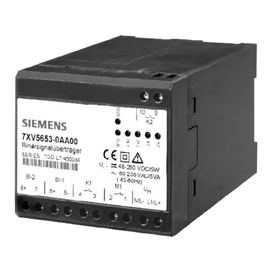
Description of the functional units Terminal assignment The signal converters inside the housing are hard-wired and tested functional units. They are provided with a clip-on mounting for a DIN EN Meaning Abbreviation 50022 top-hat rail 35 mm. Auxiliary power supply can be safely connected Voltage supply L+ AC: L1 DC: L+ at the screw-type terminals. -
Page 15: Switch Positions And Rs232 Interface
1.4.2 Switch positions and RS232 interface Description A b b r e v i a t i o n Direction as D T E The DIP switches can be operated from outside. No connection Position of the DIP-Schalter: View from the front In ←... - Page 16 Testmode off: The binary signal transducer is ready for normal operation. DIP 8 DIP 7 DIP 6 DIP 5 DIP 4 DIP 3 DIP 2 DIP 1 Meaning Block MA: Block message outputs, the relays are not controlled. Enable MA: Normal operation, message outputs are not put out.
-
Page 17: Dimensional Drawings
• with a small screwdriver, force the clips of the cover carefully toward inside of the device • change the jumper positions as shown in table 8 • snap the cover back into its position 7XV5653-0BA00 Binärsignalübertrager SERIES: TDD-M2-450085 24-250 VDC/5W... -
Page 18: Ordering Data
Ordering data Installation and commissioning Name Order No. Code Warning! 5 6 5 A 0 0 Binary signal transducer 7XV two-channel When operating electrical devices, certain parts of these devices are necessarily under dangerous voltage. Therefore, disregard of the operating notes may cause severe bodily injury or property damage. 2 binary inputs, Installation and electrical connection of the device should be performed 2 command inputs,... -
Page 19: Settings
Installation • Only optical fibres prepared according to the regulations are to be used. • The installation location should be free of vibrations. • FO types: see technical data. The admissible ambient temperature (operation or functional • The admissibla optical budget is to be observed temperature) is to be observed (see technical data). - Page 20 empty page...
- Page 21 If you have any notes or questions on this product please contact us under the following address: Siemens AG Power transmission und distribution, Secondary systems PO Box 4806 D-90026 Nuremberg Phone +49 (0)180 524 7000 Order-No.: Order location: G340B Printed in Germay...