Table of Contents
Advertisement
SITOP PSU100S
SITOP power supply
SITOP PSU100S
Operating Instructions
SITOP PSU100S 24 V/2.5 A
6EP1332-2BA20
SITOP PSU100S 24 V/5 A
6EP1333-2BA20
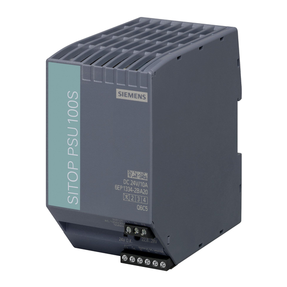
SITOP PSU100S 24 V/10 A
6EP1334-2BA20
SITOP PSU100S 24 V/20 A
6EP1336-2BA10
SITOP PSU100S 12 V/7 A
6EP1322-2BA00
SITOP PSU100S 12 V/14 A
6EP1323-2BA00
02.2013
C98130-A7589-A1-3-7629
___________________
Overview
___________________
Safety instructions
Description, device design,
___________________
dimension drawing
___________________
Mounting/removal
Mounting position, mounting
___________________
clearances
___________________
Installation
___________________
Technical data
___________________
Safety, approvals, EMC
___________________
Ambient conditions
___________________
Applications
___________________
Environment
___________________
Service & Support
1
2
3
4
5
6
7
8
9
10
11
Advertisement
Table of Contents

Related Manuals for Siemens SITOP PSU100S


Summary of Contents for Siemens SITOP PSU100S
- Page 1 ___________________ Ambient conditions ___________________ Applications ___________________ Environment ___________________ Service & Support SITOP PSU100S 24 V/2.5 A 6EP1332-2BA20 SITOP PSU100S 24 V/5 A 6EP1333-2BA20 SITOP PSU100S 24 V/10 A 6EP1334-2BA20 SITOP PSU100S 24 V/20 A 6EP1336-2BA10 SITOP PSU100S 12 V/7 A...
- Page 2 Note the following: WARNING Siemens products may only be used for the applications described in the catalog and in the relevant technical documentation. If products and components from other manufacturers are used, these must be recommended or approved by Siemens. Proper transport, storage, installation, assembly, commissioning, operation and maintenance are required to ensure that the products operate safely and without any problems.
-
Page 3: Overview
Overview Description The 1-phase SITOP PSU100S from the SITOP smart product line is a powerful, regulated standard power supply for automated machines and systems. In addition to a high efficiency, these low-profile power supply units have an outstanding overload behavior. - Page 4 Overview Ordering data The following device options are available: Regulated SITOP PSU100S power supply Type Order number 1-phase 120/230 V AC input, 6EP1332-2BA20 24 V/2.5 A DC output 1-phase 120/230 V AC input, 6EP1333-2BA20 24 V/5 A DC output 1-phase 120/230 V AC input,...
-
Page 5: Table Of Contents
Output-side connection ........................37 Technical data ............................39 Input .............................39 Output ............................41 Efficiency............................47 Closed-loop control ........................50 Protection and monitoring ......................51 MTBF ............................51 Mechanical system ........................52 Dimension drawing ........................53 Safety, approvals, EMC ........................... 55 Safety ............................55 SITOP PSU100S Operating Instructions, 02.2013, C98130-A7589-A1-3-7629... - Page 6 Series connection for increased voltage ..................63 Overload protection in the 24 V output circuit ................64 Protection against short-time voltage dips .................. 65 Protecting against longer power failures..................66 Environment ............................69 Service & Support............................ 71 SITOP PSU100S Operating Instructions, 02.2013, C98130-A7589-A1-3-7629...
-
Page 7: Safety Instructions
Before installation or maintenance work can begin, the system's main switch must be switched off and measures taken to prevent it being switched on again. If this instruction is not observed, touching live parts can result in death or serious injury. SITOP PSU100S Operating Instructions, 02.2013, C98130-A7589-A1-3-7629... - Page 8 Safety instructions SITOP PSU100S Operating Instructions, 02.2013, C98130-A7589-A1-3-7629...
-
Page 9: Description, Device Design, Dimension Drawing
Description, device design, dimension drawing Device description SITOP PSU100S is a primary-clocked power supply for connection to a 1-phase AC line supply. An electronically regulated DC voltage that can be set via a potentiometer is available at the output of the device. The output of the device is isolated, no-load proof and short-circuit proof. -
Page 10: Connections And Terminal Designation
2 screw terminals Output + ② 2 screw terminals Output – ③ One screw terminal each signal 13, 14 Figure 2-2 Terminal data for 6EP1332-2BA20, 6EP1333-2BA20, 6EP1334-2BA20, 6EP1322- 2BA00, 6EP1323-2BA00 Figure 2-3 Terminal data for 6EP1336-2BA10 SITOP PSU100S Operating Instructions, 02.2013, C98130-A7589-A1-3-7629... -
Page 11: Potentiometer
It is only permissible to use an insulated screwdriver when actuating the potentiometer. For notes on actuating the potentiometer (screwdriver, torque), refer to Figure 2-2 Terminal data for 6EP1332-2BA20, 6EP1333-2BA20, 6EP1334-2BA20, 6EP1322-2BA00, 6EP1323- 2BA00 (Page 10) and Figure 2-3 Terminal data for 6EP1336-2BA10 (Page 10). SITOP PSU100S Operating Instructions, 02.2013, C98130-A7589-A1-3-7629... -
Page 12: Status Displays And Signaling
③ Signaling contact device has tripped due to contacts 13-14 open overtemperature (reset (inactive position) possible with power OFF for approx. 30 min) SITOP PSU100S Operating Instructions, 02.2013, C98130-A7589-A1-3-7629... -
Page 13: Block Diagram
Description, device design, dimension drawing 2.5 Block diagram Block diagram Figure 2-6 Block diagram SITOP PSU100S Operating Instructions, 02.2013, C98130-A7589-A1-3-7629... -
Page 14: Dimensions And Weight
Description, device design, dimension drawing 2.6 Dimensions and weight Dimensions and weight 126,5 32,5 Figure 2-7 Dimension drawing 6EP1332-2BA20 126,5 Figure 2-8 Dimension drawing 6EP1333-2BA20, 6EP1322-2BA00 SITOP PSU100S Operating Instructions, 02.2013, C98130-A7589-A1-3-7629... - Page 15 32.5 × 125 × 120 50 × 125 × 120 70 × 125 × 120 115 × 145 × 150 D) in mm Weight Approx. 0.3 kg Approx. 0.4 kg Approx. 0.7 kg Approx. 2.4 kg SITOP PSU100S Operating Instructions, 02.2013, C98130-A7589-A1-3-7629...
- Page 16 Description, device design, dimension drawing 2.6 Dimensions and weight SITOP PSU100S Operating Instructions, 02.2013, C98130-A7589-A1-3-7629...
-
Page 17: Mounting/Removal
WARNING Installing the device in a housing or a control cabinet SITOP PSU100S power supplies are built-in units. They must be installed in a housing or control cabinet where only qualified personnel have access. The device can be snapped onto a standard mounting rail EN 60715 35×7.5/15 for installation in a control cabinet. - Page 18 If the device is to be used in a hazardous zone (Ex II 3G Ex nA nC IIC T4 Gc) it must be installed in a distributor box with degree of protection IP54 or higher. SITOP PSU100S Operating Instructions, 02.2013, C98130-A7589-A1-3-7629...
-
Page 19: Mounting Position, Mounting Clearances
Output current as a function of the ambient temperature and mounting height 120 V 230 V Figure 4-1 6EP1332-2BA20: Output current in the standard mounting position 120 V 230 V Figure 4-2 6EP1333-2BA20: Output current in the standard mounting position SITOP PSU100S Operating Instructions, 02.2013, C98130-A7589-A1-3-7629... - Page 20 6EP1334-2BA20: Output current in the standard mounting position 120 V 230 V Figure 4-4 6EP1336-2BA10: Output current in the standard mounting position 120 V 230 V Figure 4-5 6EP1322-2BA00: Output current in the standard mounting position SITOP PSU100S Operating Instructions, 02.2013, C98130-A7589-A1-3-7629...
- Page 21 4.1 Standard mounting position 120 V 230 V Figure 4-6 6EP1323-2BA00: Output current in the standard mounting position 1000 2000 3000 4000 -1000 Figure 4-7 Mounting height derating Details see chapter Ambient conditions (Page 59) SITOP PSU100S Operating Instructions, 02.2013, C98130-A7589-A1-3-7629...
-
Page 22: Other Mounting Positions
4.2.1 6EP1332-2BA20 120 V 230 V Figure 4-8 Mounting position (1) 120 V 230 V SITOP PSU100S Figure 4-9 Mounting position (2) SITOP PSU100S Operating Instructions, 02.2013, C98130-A7589-A1-3-7629... - Page 23 Mounting position, mounting clearances 4.2 Other mounting positions 120 V 230 V Figure 4-10 Mounting position (3) 120 V 230 V Figure 4-11 Mounting position (4) 120 V 230 V Figure 4-12 Mounting position (5) SITOP PSU100S Operating Instructions, 02.2013, C98130-A7589-A1-3-7629...
-
Page 24: 6Ep1333-2Ba20
4.2 Other mounting positions 4.2.2 6EP1333-2BA20 120 V 230 V Figure 4-13 Mounting position (1) 120 V 230 V SITOP PSU100S Figure 4-14 Mounting position (2) 120 V 230 V Figure 4-15 Mounting position (3) SITOP PSU100S Operating Instructions, 02.2013, C98130-A7589-A1-3-7629... - Page 25 Mounting position, mounting clearances 4.2 Other mounting positions 120 V 230 V Figure 4-16 Mounting position (4) 120 V 230 V Figure 4-17 Mounting position (5) SITOP PSU100S Operating Instructions, 02.2013, C98130-A7589-A1-3-7629...
-
Page 26: 6Ep1334-2Ba20
4.2 Other mounting positions 4.2.3 6EP1334-2BA20 120 V 230 V Figure 4-18 Mounting position (1) 120 V 230 V SITOP PSU100S Figure 4-19 Mounting position (2) 120 V 230 V Figure 4-20 Mounting position (3) SITOP PSU100S Operating Instructions, 02.2013, C98130-A7589-A1-3-7629... - Page 27 Mounting position, mounting clearances 4.2 Other mounting positions 120 V 230 V Figure 4-21 Mounting position (4) 120 V 230 V Figure 4-22 Mounting position (5) SITOP PSU100S Operating Instructions, 02.2013, C98130-A7589-A1-3-7629...
-
Page 28: 6Ep1336-2Ba10
4.2 Other mounting positions 4.2.4 6EP1336-2BA10 120 V 230 V Figure 4-23 Mounting position (1) 120 V 230 V SITOP PSU100S Figure 4-24 Mounting position (2) 120 V 230 V Figure 4-25 Mounting position (3) SITOP PSU100S Operating Instructions, 02.2013, C98130-A7589-A1-3-7629... - Page 29 Mounting position, mounting clearances 4.2 Other mounting positions 120 V 230 V Figure 4-26 Mounting position (4) 120 V 230 V Figure 4-27 Mounting position (5) SITOP PSU100S Operating Instructions, 02.2013, C98130-A7589-A1-3-7629...
-
Page 30: 6Ep1322-2Ba00
4.2 Other mounting positions 4.2.5 6EP1322-2BA00 120 V 230 V Figure 4-28 Mounting position (1) 120 V 230 V SITOP PSU100S Figure 4-29 Mounting position (2) 120 V 230 V Figure 4-30 Mounting position (3) SITOP PSU100S Operating Instructions, 02.2013, C98130-A7589-A1-3-7629... - Page 31 Mounting position, mounting clearances 4.2 Other mounting positions 120 V 230 V Figure 4-31 Mounting position (4) 120 V 230 V Figure 4-32 Mounting position (5) SITOP PSU100S Operating Instructions, 02.2013, C98130-A7589-A1-3-7629...
-
Page 32: 6Ep1323-2Ba00
4.2 Other mounting positions 4.2.6 6EP1323-2BA00 120 V 230 V Figure 4-33 Mounting position (1) 120 V 230 V SITOP PSU100S Figure 4-34 Mounting position (2) 120 V 230 V Figure 4-35 Mounting position (3) SITOP PSU100S Operating Instructions, 02.2013, C98130-A7589-A1-3-7629... - Page 33 Mounting position, mounting clearances 4.2 Other mounting positions 120 V 230 V Figure 4-36 Mounting position (4) 120 V 230 V Figure 4-37 Mounting position (5) SITOP PSU100S Operating Instructions, 02.2013, C98130-A7589-A1-3-7629...
- Page 34 Mounting position, mounting clearances 4.2 Other mounting positions SITOP PSU100S Operating Instructions, 02.2013, C98130-A7589-A1-3-7629...
-
Page 35: Installation
Line-side connection The SITOP PSU100S power supply is designed for connection to a 1-phase AC line supply (TN or TT system according to VDE 0100 T 300 / IEC 364-3) with a rated voltage of 120/230 V AC, 50/60 Hz. - Page 36 Miniature circuit breaker (IEC 898) characteristic C, 10 A The protective conductor of the line supply must be connected at the PE terminal. Other country-specific regulations may have to be observed when installing the device. SITOP PSU100S Operating Instructions, 02.2013, C98130-A7589-A1-3-7629...
-
Page 37: Output-Side Connection
5.2 Output-side connection Output-side connection At its output, the SITOP PSU100S power supply provides an isolated (= non-grounded) SELV output voltage (Safety Extra Low Voltage). The output of the power supply is no-load, overload, and short-circuit proof. If an overload occurs, the electronic current limitation limits the output current to a maximum value (refer to chapter Technical data (Page 39)). - Page 38 Installation 5.2 Output-side connection SITOP PSU100S Operating Instructions, 02.2013, C98130-A7589-A1-3-7629...
-
Page 39: Technical Data
2.5 A I²t, at 230 V AC, max. 0.4 A 1.0 A 5.6 A 10 A Integrated input fuse Fuse T 3.15 A Fuse T 3.15 A Fuse T 6 A Fuse T 10 A SITOP PSU100S Operating Instructions, 02.2013, C98130-A7589-A1-3-7629... - Page 40 5.6 A Integrated input fuse Fuse T 3,15 A Fuse T 6 A Protection in the line feeder required: Circuit breaker, C required: Circuit breaker, C cable (IEC 898) characteristic, 3 A characteristic, 6 A SITOP PSU100S Operating Instructions, 02.2013, C98130-A7589-A1-3-7629...
-
Page 41: Output
Output voltage setting Using a potentiometer Remark Max. 480 W Status display LED green for 24 V O.K. Signaling Relay contact (NO contact, rating 60 V DC /0.3 A) for 24 V O.K. SITOP PSU100S Operating Instructions, 02.2013, C98130-A7589-A1-3-7629... - Page 42 2.5 s Remark Can be connected in parallel to increase the power rating Number of devices that can be connected in parallel to increase the power rating, units SITOP PSU100S Operating Instructions, 02.2013, C98130-A7589-A1-3-7629...
- Page 43 84 W 168 W Overload capability (Extra 10.5 A for 5 s/min 21 A for 5 s/min Power) Short-time overload current / for 26 A 48 A a short circuit when powering up / typical SITOP PSU100S Operating Instructions, 02.2013, C98130-A7589-A1-3-7629...
- Page 44 Output characteristic see diagram, output see diagram, output characteristic for 6EP1322- characteristic for 6EP1323- 2BA20 (Page 46) 2BA20 (Page 46) Capacitive load, max. 2 mF/A Figure 6-2 Startup delay/voltage rise SITOP PSU100S Operating Instructions, 02.2013, C98130-A7589-A1-3-7629...
- Page 45 Technical data 6.2 Output Figure 6-3 Output characteristic 6EP1332-2BA20 Figure 6-4 Output characteristic 6EP1333-2BA20 Figure 6-5 Output characteristic 6EP1334-2BA20 SITOP PSU100S Operating Instructions, 02.2013, C98130-A7589-A1-3-7629...
- Page 46 Output characteristic 6EP1322-2BA00 Figure 6-8 Output characteristic 6EP1323-2BA00 The device supplies a constant output voltage until the current limit is reached. In the event of an overload, the output current and the output voltage are reduced. SITOP PSU100S Operating Instructions, 02.2013, C98130-A7589-A1-3-7629...
-
Page 47: Efficiency
Power loss when idling 1.5 W / 1.0 W 2.8 W / 2.3 W 120 V / 230 V AC approx. 2,5 A 2,5 A 1,25 A 1,875 A 1,875 A 1,25 A Figure 6-9 Efficiency 6EP1332-2BA20 SITOP PSU100S Operating Instructions, 02.2013, C98130-A7589-A1-3-7629... - Page 48 Technical data 6.3 Efficiency 2,5 A 3,75 A 3,75 A 2,5 A Figure 6-10 Efficiency 6EP1333-2BA20 7,5 A 7,5 A 10 A 10 A Figure 6-11 Efficiency 6EP1334-2BA20 SITOP PSU100S Operating Instructions, 02.2013, C98130-A7589-A1-3-7629...
- Page 49 Technical data 6.3 Efficiency 15 A 15 A 10 A 20 A 10 A 20 A Figure 6-12 Efficiency 6EP1336-2BA10 5,25 A 5,25 A 3,5 A 3,5 A Figure 6-13 Efficiency 6EP1322-2BA00 SITOP PSU100S Operating Instructions, 02.2013, C98130-A7589-A1-3-7629...
-
Page 50: Closed-Loop Control
Load-step settling time 2 ms 10 to 90 %, typ. Load-step settling time 1 ms 10 ms 1 ms 90 to 10 %, max. Load-step settling time 2 ms 90 to 10 %, typ. SITOP PSU100S Operating Instructions, 02.2013, C98130-A7589-A1-3-7629... -
Page 51: Protection And Monitoring
6EP1333-2BA20 6EP1334-2BA20 6EP1322-2BA00 6EP1323-2BA00 Mean Time Between Failures SN29500: SN29500: > 1600000 h >500000 h (typ. 700000 h) at 40 °C, rated load, 24 h operation at 40° C, rated load, 24 h operation SITOP PSU100S Operating Instructions, 02.2013, C98130-A7589-A1-3-7629... -
Page 52: Mechanical System
Type of mounting / panel mounting Type of mounting / rail mounting Type of mounting / S7- 300 rail mounting Mounting Can be snapped onto standard EN 60715 35x7,5/15 mounting rails SITOP PSU100S Operating Instructions, 02.2013, C98130-A7589-A1-3-7629... -
Page 53: Dimension Drawing
Technical data 6.8 Dimension drawing Dimension drawing See chapter Dimensions and weight (Page 14) CAD data that can be downloaded from the Internet: 6EP1332-2BA20 (http://www.automation.siemens.com/bilddb/index.aspx?objKey=G_KT01_XX_00727) 6EP1333-2BA20 (http://www.automation.siemens.com/bilddb/index.aspx?objKey=G_KT01_XX_00730) 6EP1334-2BA20 (http://www.automation.siemens.com/bilddb/index.aspx?objKey=G_KT01_XX_00733) 6EP1336-2BA10 (http://www.automation.siemens.com/bilddb/index.aspx?objKey=G_KT01_XX_00720) 6EP1322-2BA00 (http://www.automation.siemens.com/bilddb/index.aspx?objKey=G_KT01_XX_00736) 6EP1323-2BA00 (http://www.automation.siemens.com/bilddb/index.aspx?objKey=G_KT01_XX_00739) SITOP PSU100S Operating Instructions, 02.2013, C98130-A7589-A1-3-7629... - Page 54 Technical data 6.8 Dimension drawing SITOP PSU100S Operating Instructions, 02.2013, C98130-A7589-A1-3-7629...
-
Page 55: Safety, Approvals, Emc
Transformer according to EN 61558-2-16 Protection class Class I Degree of protection (EN 60529) IP20 Leakage current, typ. 1 mA Leakage current, max. 3.5 mA Test voltage See Table 7-1 Test voltage (Page 56) SITOP PSU100S Operating Instructions, 02.2013, C98130-A7589-A1-3-7629... -
Page 56: Test Voltage
1500 VAC 1500 VAC 350 VAC Field test 2200 VDC 2200 VDC 500 VDC 1500 VAC 1500 VAC 350 VAC Remark: Tripping current for DC measurement: 0 mA Tripping current for AC measurement: <100 mA SITOP PSU100S Operating Instructions, 02.2013, C98130-A7589-A1-3-7629... -
Page 57: Approvals
ATEX EX II 3G Ex nA nC IIC T4 Gc; cCSAus Class I, Div. 2, GROUPS A, B, C, D, T4 CB approval CB-Scheme IEC 60950-1 SEMI F47 compliance Not tested fulfilled Marine approvals Germanischer Lloyd (GL) available Germanischer Lloyd (GL) soon SITOP PSU100S Operating Instructions, 02.2013, C98130-A7589-A1-3-7629... -
Page 58: Emc
100% for 5000 ms Emitted interference EN 55022 Class B Class B Line harmonics EN 61000-3-2 Class A Class A limitation Generic standards EN 61000-6-2 Immunity for industrial environments EN 61000-6-3 Emission for residential areas SITOP PSU100S Operating Instructions, 02.2013, C98130-A7589-A1-3-7629... -
Page 59: Ambient Conditions
-40 ... +85° C Tests (packed for shipping) according to: EN 60068-2-1 cold EN 60068-2-2 dry heat EN 60068-2-30 humid heat, cyclic Humidity class Climatic class 3K3 according to EN 60721, without condensation SITOP PSU100S Operating Instructions, 02.2013, C98130-A7589-A1-3-7629... - Page 60 Figure 4-7 Mounting height derating (Page 21) Overvoltage category: III up to 2000 m (EN 50178) II from 2000 m up to 6000 m (EN 50178) Storage: 1080 ... 660 hPa (-1000 ... +3500 m) SITOP PSU100S Operating Instructions, 02.2013, C98130-A7589-A1-3-7629...
-
Page 61: Applications
Applications Parallel connection to increase power rating To increase the power rating, two SITOP PSU100S power supplies of the same type can be directly connected in parallel. The following must be observed: ● The cables connected to each power supply at terminals "+" and "-" must have identical lengths and the same cable cross-sections (or the same impedance) up to a common external connection point (terminal strip) if possible. -
Page 62: Parallel Connection For Redundancy
"+" terminal of the power supply and the common connection point. Parallel connection for redundancy Connecting several SITOP PSU100S power supplies in parallel for redundancy purposes is required if especially high demands are placed regarding the availability of a reliable 24 V power supply. -
Page 63: Series Connection For Increased Voltage
Series connection for increased voltage To achieve an output voltage of 48 V DC, two 24 V SITOP PSU100S power supplies of the same type can be connected in series. In this case, connect the "-" terminal of the first power supply to the "+"... -
Page 64: Overload Protection In The 24 V Output Circuit
9.4 Overload protection in the 24 V output circuit Overload protection in the 24 V output circuit If overload occurs, the electronic current limiting of the SITOP PSU100S power supply limits the output current to a maximum value (refer to chapter Technical data (Page 39)). The... -
Page 65: Protection Against Short-Time Voltage Dips
9.5 Protection against short-time voltage dips Protection against short-time voltage dips For a drop in the line-side supply voltage, the SITOP PSU100S power supply still maintains the output voltage for a short time in the millisecond range (see Chapter Technical data (Page 39)). -
Page 66: Protecting Against Longer Power Failures
SITOP UPS500 DC-UPS modules based on capacitors (Figure 9-6 24 V buffering to allow the saving of process data and controlled shutdown of PCs (Page 66)). Figure 9-6 24 V buffering to allow the saving of process data and controlled shutdown of PCs SITOP PSU100S Operating Instructions, 02.2013, C98130-A7589-A1-3-7629... - Page 67 PC-based automation solutions. This supports further processing of the status signals and safely running down the PC. You can find additional information at: DC UPS with capacitors manual (http://support.automation.siemens.com/WW/view/en/48932766/133300) DC UPS with batteries manual (http://support.automation.siemens.com/WW/view/en/48934855/133300) SITOP PSU100S Operating Instructions, 02.2013, C98130-A7589-A1-3-7629...
- Page 68 Applications 9.6 Protecting against longer power failures SITOP PSU100S Operating Instructions, 02.2013, C98130-A7589-A1-3-7629...
-
Page 69: Environment
The device is in conformance with RoHS. As a rule, only non-silicon precipitating materials are used. Disposal guidelines Packaging and packaging aids can and should always be recycled. The product itself may not be disposed of as domestic refuse. SITOP PSU100S Operating Instructions, 02.2013, C98130-A7589-A1-3-7629... - Page 70 Environment SITOP PSU100S Operating Instructions, 02.2013, C98130-A7589-A1-3-7629...
-
Page 71: Service & Support
● Phone: + 49 (0) 911 895 7222 ● E-Mail (mailto:support.automation@siemens.com) ● Internet: Online support request form (http://www.siemens.de/automation/support-request) Technical documentation on the Internet Operating instructions and manuals for SITOP are available in the Internet: Operating instructions/manuals (http://www.siemens.de/sitop/manuals) SITOP power supply homepage General news about our power supplies is available in the Internet at the SITOP homepage: SITOP (http://www.siemens.de/sitop) - Page 72 Service & Support Contact persons If you have any questions regarding the use of our products, then contact the Siemens contact person in your regional Siemens sales office. You can find these addresses as follows: ● On the Internet (http://www.siemens.de/automation/partner) ●...