Panasonic TY-FB9TU Service Manual
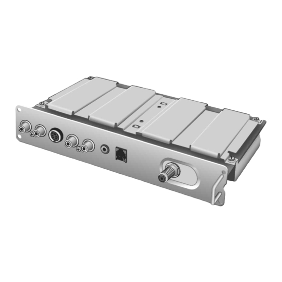
U/v tuner board with mate i/f board
Hide thumbs
Also See for TY-FB9TU:
- Operating instructions manual (32 pages) ,
- Service manual (41 pages)
Table of Contents
Advertisement
Quick Links
Specification
Channel Capability-181
Connection Terminals
AV INPUT
AV OUTPUT
Digital interface port
(MATE)
Remote Control Model No. N2QAFB000003
Mass (weight)
Operating range
CONTENTS
1 Safety Precautions
1.1. General Guidelines
U/V Tuner Board with MATE I/F Board
VHF-12: UHF-56: Cable-125
VIDEO (RCA PIN JACK TYPE) 1.0 Vp-p (75 W)
S VIDEO (Mini DIN 4-pin) Y: 1.0 Vp-p (75 W), C: 0.286 Vp-p (75 W)
AUDIO L-R (RCA PIN JACK TYPE) 0.5 Vrms
Video (RCA PIN JACK TYPE) 1.0 Vp-p (75 W)
*Cannot output UHF/VHF signals.
AUDIO L-R (M3 JACK TYPE) 0.5 Vrms
RJ-11C
approx. 160 g (5.6 oz) (including batteries)
approx. 7 m (23 feet) directly in front of the unit
Page
TY-FB9TU
3
2 Prevention of Electro Static Discharge (ESD) to
3
Electrostatically Sensitive (ES) Devices
3 About lead free solder (PbF)
© 2006 Matsushita Electric Industrial Co., Ltd. All
rights
distribution is a violation of law.
ORDER NO.ITD0604018CE
D10 Canada: B07
reserved.
Unauthorized
copying
Page
4
5
and
Advertisement
Table of Contents

Related Manuals for Panasonic TY-FB9TU


Summary of Contents for Panasonic TY-FB9TU
- Page 1 ORDER NO.ITD0604018CE D10 Canada: B07 U/V Tuner Board with MATE I/F Board TY-FB9TU Specification Channel Capability-181 VHF-12: UHF-56: Cable-125 Connection Terminals VIDEO (RCA PIN JACK TYPE) 1.0 Vp-p (75 W) AV INPUT S VIDEO (Mini DIN 4-pin) Y: 1.0 Vp-p (75 W), C: 0.286 Vp-p (75 W) AUDIO L-R (RCA PIN JACK TYPE) 0.5 Vrms...
-
Page 2: Table Of Contents
TY-FB9TU 4 Installation 8.4. HMB-Board (2 of 4) Schematic Diagram 5 Antenna connection 8.5. HMB-Board (3 of 4) Schematic Diagram 6 Connection of external equipment 8.6. HMB-Board (4 of 4) Schematic Diagram 7 Circuit Board Layout 9 Replacement Parts List 7.1. - Page 3 TY-FB9TU 1 Safety Precautions 1.1. General Guidelines 1. When servicing, observe the original lead dress. If a short circuit is found, replace all parts which have been overheated or damaged by the short circuit. 2. After servicing, see to it that all the protective devices such as insulation barriers, insulation papers shields are properly installed.
- Page 4 TY-FB9TU 2 Prevention of Electro Static Discharge (ESD) to Electrostatically Sensitive (ES) Devices Some semiconductor (solid state) devices can be damaged easily by static electricity. Such components commonly are called Electrostatically Sensitive (ES) Devices. Examples of typical ES devices are integrated circuits and some field-effect transistors and semiconductor "chip"...
- Page 5 TY-FB9TU 3 About lead free solder (PbF) Note: Lead is listed as (Pb) in the periodic table of elements. In the information below, Pb will refer to Lead solder, and PbF will refer to Lead Free Solder. The Lead Free Solder used in our manufacturing process and discussed below is (Sn+Ag+Cu).
-
Page 6: Installation
TY-FB9TU 4 Installation... -
Page 7: Antenna Connection
TY-FB9TU 5 Antenna connection... -
Page 8: Connection Of External Equipment
TY-FB9TU 6 Connection of external equipment... -
Page 9: Circuit Board Layout
TY-FB9TU 7 Circuit Board Layout 7.1. HMB-Board HMB-BOARD (FOIL SIDE) TXNHMB1ZUTU TNPA4059 1 HMB ORDER CR No.3 R482 R419 R407 R451 R443 R312 R310 R420 R442 IC401 C251 TS054 R313 R468 R469 R480 C462 L105 C451 R470 R486 C252 R471... - Page 10 TY-FB9TU HMB-BOARD (COMPONENT SIDE) TXNHMB1ZUTU R098 R089 C066 C329 C324 C327 R087 C330 C445 C093 C321 C320 Q055 C459 Q054 R418 R401 Q056 JS507 TS052 LC409 C071 C069 JS506 C516 C319 C318 C322 R091 Q057 C060 C266 C062 R251 C094...
-
Page 11: Block And Schematic Diagram
TY-FB9TU 8 Block and Schematic Diagram 8.1. Schematic Diagram Notes... -
Page 12: Hmb-Board Block Diagram
TY-FB9TU 8.2. HMB-Board Block Diagram +9V1 U/V Tuner Board with MATE I/F IC3301 IC3702 IC3201 IC3701 +5V1 MEM 3.3V 3.3V +5V1 Q3056 Q3057 MEMORY MEMORY MUTE IC3302 IC3101 Q3052 FIFO FIFO JK3005 IC3251 +3.3V1 +3.3V1 IC3103 AD 2.5V AD 2.5V... -
Page 13: Hmb-Board (1 Of 4) Schematic Diagram
TY-FB9TU 8.3. HMB-Board (1 of 4) Schematic Diagram C3460 C3440 R3404 R3464 R3430 0.1u 4.7k 0.1u HMB-BOARD TXNHMB1ZUTU (1/4) LC3401 IC3403 ELKE103FA C0EBE0000120 C3406 C3405 6.3V RESET 100u 0.1u C3468 IC3401 0.1u C0DBEZE00006 3.3V FOR LOADER BUS CONTROL BUS CONTROL... -
Page 14: Hmb-Board (2 Of 4) Schematic Diagram
C3207 C3093 C3216 C3217 C3094 Q3053 220u 2SD0601A0L Q3057 R3085 2SB0709A0L Q3056 2SB0709A0L R3091 180k R3086 R3093 R3096 IC3301 D3053 D3054 MA2J11100L MA2J11100L C0CBABB00029 MEM 3.3V TY-FB9TU HMB-Board (2 of 4) Schematic Diagram TY-FB9TU HMB-Board (2 of 4) Schematic Diagram... -
Page 15: Hmb-Board (3 Of 4) Schematic Diagram
C3158 C3156 6.3V 6.3V 0.1u C3138 C3146 6.3V 0.1u C3157 6.3V C3135 C3150 0.01u 0.01u PLL2.5V R3152 R3153 C3136 C3140 R3156 R3157 100p C3151 C3153 100p TY-FB9TU HMB-Board (3 of 4) Schematic Diagram TY-FB9TU HMB-Board (3 of 4) Schematic Diagram... -
Page 16: Hmb-Board (4 Of 4) Schematic Diagram
R3302 SCL2 POW_DOWN R3311 SDA2 3.3V PLL2.5V R3305 C3309 C3313 CLK_SEL R3310 IC3699 C3EBGC000065 IC3303 EEPROM C3317 AN80L25RMSTX PLL 2.5V R3308 R3309 R3337 SCL2 SDA2 R3338 TY-FB9TU TY-FB9TU HMB-Board (4 of 4) Schematic Diagram HMB-Board (4 of 4) Schematic Diagram... -
Page 17: Replacement Parts List
TY-FB9TU 9 Replacement Parts List 9.1. Replacement Parts List Notes... -
Page 18: Electrical Replacement Parts List
TY-FB9TU 9.2. Electrical Replacement Parts List Ref. Part No. Part Name & Remarks Ref. Part No. Part Name & Remarks Description Description C3152 ECJ1XB1C104K C 0.1UF, Z, 16V C3001,0 ECJ2XB1E104K C 0.1UF, K, 25V C3153 ECJ1XC1H101J C 100PF, J, 50V... - Page 19 TY-FB9TU Ref. Part No. Part Name & Remarks Ref. Part No. Part Name & Remarks Description Description C3432 ECJ2VF1H103Z C 0.010UF, Z, 50V IC3201 C3HBKZ000002 C3433 EEEHB1C470P C 47PF, J, 16V IC3251 C0ZBZ0000967 C3434,3 ECJ1VB1H221K C 220UF, K, 50V IC3301...
- Page 20 TY-FB9TU Ref. Part No. Part Name & Remarks Ref. Part No. Part Name & Remarks Description Description Q3104 2SD1030 TRANSISTOR R3106 ERJ3GEYJ103 M 10KOHM,J,1/16W Q3350 2SD601A TRANSISTOR R3107 ERJ3GEYJ330 M 33 OHM,J,1/16W Q3352- 2SD601A TRANSISTOR R3108 ERJ3GEY0R00 M 0 OHM, 1/16W...
- Page 21 TY-FB9TU Ref. Part No. Part Name & Remarks Ref. Part No. Part Name & Remarks Description Description R3352 ERJ3GEYJ101 M 100 OHM,J,1/16W R3480 ERJ3GEYJ103 M 10KOHM,J,1/16W R3353,5 ERJ3GEYJ103 M 10KOHM,J,1/16W R3481,8 ERJ3GEY0R00 M 0 OHM, 1/16W R3356 ERJ3GEY0R00 M 0 OHM, 1/16W...
-
Page 22: Mechanical Replacement Parts List
TY-FB9TU 9.3. Mechanical Replacement Parts List Ref. Part No. Part Name & Remarks Description J0KF00000018 FERRITE CORE (CHAP.5) K1RGZBA00001 F TERMINAL (5C TYPE) N2QAFB000003 REMOTE CONTROL TBMU662 TERMINAL SHEET THEL0239 SCREW FOR INSTALLATION THEL027N SCREW FOR SHIELD PLATE THNA004N NUT FOR TUNER... -
Page 23: Parts Location (1)
TY-FB9TU 9.4. Parts Location (1) -
Page 24: Parts Location (2)
TY-FB9TU 9.5. Parts Location (2)