Brother P-touch QL-710W Service Manual
High-speed label printer
Hide thumbs
Also See for P-touch QL-710W:
- Quick setup manual (93 pages) ,
- Network user's manual (48 pages) ,
- Software user's manual (48 pages)
Table of Contents
Advertisement
Quick Links
Advertisement
Table of Contents
Troubleshooting

Related Manuals for Brother P-touch QL-710W


Summary of Contents for Brother P-touch QL-710W
- Page 1 P-touch SERVICE MANUAL MODEL: QL-710W/720NW...
- Page 2 PREFACE This publication is a service manual covering the specifications, theory of operation, disassembly/ reassembly procedure, and troubleshooting the Brother QL-710W/720NW. It is intended for service personnel and other concerned persons to accurately and quickly provide after-sale service for our QL-710W/720NW.
-
Page 3: Table Of Contents
CONTENTS CHAPTER I SPECIFICATIONS 1.1 MECHANICAL SPECIFICATIONS..................I-1 1.1.1 External Appearance ......................I-1 1.1.2 Control Button and LED .....................I-1 1.1.3 Display..........................I-2 1.1.4 Printing Mechanism......................I-2 1.1.5 Thermal Tape........................I-3 1.1.6 Cutter ...........................I-4 1.1.7 PC Interface .........................I-4 1.2 ELECTRONICS SPECIFICATIONS ..................I-4 1.2.1 Character Generator......................I-4 1.2.2 Power Supply........................I-4 CHAPTER II THEORY OF OPERATION 2.1 OUTLINE OF MECHANISMS ..................... - Page 4 Removing the Back Cover.................... III-15 Removing the Power Supply ASSY and the Main PCB ASSY........III-16 Removing the Sub ASSY Inlet..................III-19 Removing the Media PCB ASSY ................III-20 Removing the Mecha ASSY ..................III-21 [10] Removing the Cutter Unit ASSY ................. III-22 [11] Disassembling the Mecha ASSY..................
- Page 5 1.3.1 Role of the Serviceman Software Tool ................1-8 1.3.2 Operating procedure of the Serviceman Software Tool ............. 1-8 1.4 Precautions..........................1-11 1.4.1 Precautions for inspecting Chinese model ............... 1-11 1.4.2 Precautions for all models completed inspections............1-11 1.4.3 Precautions for Chinese model completed inspections ............ 1-11 1.5 Read serial no ........................
-
Page 6: Chapter Ispecifications
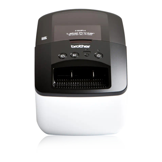
CHAPTER I SPECIFICATIONS 1.1 MECHANICAL SPECIFICATIONS 1.1.1 External Appearance (1) Dimensions (W x D x H) 128mm x 236mm x 153mm (2) Weight Approx. 1.20kg (Machine proper only) Approx. 2.22kg (In package) 153mm 128mm 236mm Fig. 1.1-1 External Appearance 1.1.2 Control Button and LED (1) Number of buttons 4 (ON/OFF, Wi-Fi, Feed, Cut) -
Page 7: Display
1.1.3 Display (1) Display type (Wi-Fi LED; green Status LED; green, orange, red) 1.1.4 Printing Mechanism (1) Print method Direct thermal printing with thermal head Printing on thermal paper tape, and printing on thermal paper and thermal plastic tape (with fixed head and tape feeding) (2) Highest printing speed Max. -
Page 8: Thermal Tape
1.1.5 Thermal Tape (1) Tape Roll type (Die cut and free length) (2) Type and size of die cut tape Label size Roll overall Number of label Type of tape (W x H) width sheets Standard Address 29mm x 90mm 32mm 400 sheets/roll Large Address... -
Page 9: Cutter
Windows; Microsoft Windows XP/Windows Vista/Windows 7 Macintosh; Mac OS X 10.4.11-10.6 (only with P-touch Editor 5.x) (3) Printer emulation PT CBP (Brother original) ESC/P (only for 720NW) P-touch template (only for 720NW) (4) Accessories Editor Dedicated editor is included. USB IF cable Standard USB cable is included. -
Page 10: Chapter Ii Theory Of Operation
CHAPTER II THEORY OF OPERATION 2.1 OUTLINE OF MECHANISMS 2.1.1 Print Mechanism Structure of Thermal Head This machine adopts direct thermal printing system. The thermal head consists of 720 pieces of heating elements arrayed in vertical single row as shown in the Fig.2.1-1. The dimension of each heating element is vertical length 0.0847 (0.0847mm pitch) x horizontal width 0.13mm. -
Page 11: Press Contact And Release Mechanism Of Thermal Head
2.1.2 Press Contact and Release Mechanism of Thermal Head The head ASSY is pressed firmly against on the platen ASSY by the force of head spring L. When open the top cover ASSY, the release gear and release shaft are turned via link lever and platen release lever and the release shaft presses down the head ASSY. -
Page 12: Tape Feed Mechanism
2.1.3 Tape Feed Mechanism When the tape is set, the tape is pressed against the thermal head, which is nipped between the platen and the thermal head. At this time the tape feed motor ASSY (step motor) rotates, and its drive power is transmitted to the platen gear and the platen via the gear train, and consequently the platen can feed the tape. -
Page 13: Automatic Tape Full Cutter Mechanism
2.1.4 Automatic Tape Full Cutter Mechanism The automatic tape full cutter mechanism moves the moving cutter blade up and down to the direction of the fixed cutter blade to cut the tape on the feeding pass. The cam is rotated once so that the moving cutter blade moves up and down and cuts a medium. -
Page 14: Cover Open (Cover Lock) Sensor (Push Switch
2.1.5 Cover Open (Cover Lock) Sensor (Push Switch) The cover open (cover lock) sensor (push switch) is mounted on the SB PCB ASSY. Closing the top cover ASSY, the cover sensor arm pushes the cover open (cover lock) sensor (push switch) and the signal of the top cover ASSY close status is output. Top cover ASSY Cover sensor arm SB PCB ASSY... -
Page 15: Outline Of Control Electronics
2.2 OUTLINE OF CONTROL ELECTRONICS Fig. 2.2-1 and Fig. 2.2-2 show the block diagram of the control electronics. The control electronics consist of the following components. QL-710W CN11 Wi-Fi PCB ASSY CN10 Full cutter motor SB PCB ASSY Tape feed motor Thermal head Power supply ASSY Cutter sensor... -
Page 16: Main Pcb Assy
QL-720NW Serial Ethernet CN13 CN11 CN12 Wi-Fi PCB ASSY CN10 Full cutter motor SB PCB ASSY Tape feed motor Thermal head Power supply ASSY Cutter sensor Media type detect switch PCB Media position detect sensor PCB Fig. 2.2-2 Block Diagram of the Control Electronics (QL-720NW) 2.2.1 Main PCB ASSY This manages all the components. -
Page 17: Button, Led Pcb (Sb Pcb Assy
2.2.4 Button, LED PCB (SB PCB ASSY) This is the PCB equipped with ON/OFF button, Feed button, Cut button, Wi-Fi button, cover open sensor, LED lamp (Green/Red) and Green LED. 2.2.5 Cutter Sensor (Cutter Home Position Detect Sensor) This sensor detects existence of the cutter at its home position (micro switch). 2.2.6 Media Feed Motor (Tape Feed Motor ASSY) The media feed motor supplies the drive power to feed media. -
Page 18: Main Pcb
2.3 MAIN PCB Fig. 2.3-1 shows the block diagram of the main PCB. The main PCB consists of the following components. (1) CPU (Including ROM and RAM) (2) EEPROM (16Kbit) (3) Power supply ON/OFF circuit, Feed button ON/OFF circuit, Cut button ON/OFF circuit, LED ON/OFF circuit (4) Head power supply ON/OFF circuit (5) Full cutter motor driver circuit and Media feed motor driver circuit... - Page 19 2.3.1 Media Type Detect Sensor Circuit, Media Position Detect Sensor Circuit and Cover Open Sensor Circuit (1) Media type detect sensor circuit The sensor circuit consists of media sensor with five switch systems (CAS1 through CAS5). Loading a tape cassette, some of five switches turn on and the others retain off according to the configuration of its' ID code apertures.
-
Page 20: Chapter Iii Disassembly And Reassembly
CHAPTER III DISASSEMBLY AND REASSEMBLY 3.1 SAFETY PRECAUTIONS (1) The disassembly or reassembly work should be carried on a grounded antistatic sheet. Otherwise, the LSIs and electronic parts may be damaged due to the electricity charged in your body. (2) When transporting PCBs, be sure to wrap them in conductive sheets such as aluminum foil. -
Page 21: Tightning Torque Lists
3.2 TIGHTNING TORQUE LISTS Tightening torque Location Screw type Q'ty N · cm Top cover ASSY Taptite, bind B M2.6x8 0.343 ± 0.049 Lower plate ASSY Taptite, bind B M2.6x8 0.343 ± 0.049 Panel cover Taptite, bind B M2.6x8 0.343 ± 0.049 SB PCB ASSY Taptite, bind B M2.6x8 0.343 ±... -
Page 22: Lubrication Points List
3.3 LUBRICATION POINTS LIST * Grease to be used: Grease B (rice-grain sized) Release shaft * Grease to be used: Grease B (rice-grain sized) * Grease to be used: Grease B (rice-grain sized) Head ASSY Mecha ASSY III - 3... - Page 23 Platen gear * Grease to be used: Silicon grease G501 (rice-grain sized) Double gear C III - 4...
-
Page 24: Disassembly Procedure
3.4 DISASSEMBLY PROCEDURE Removing the Thermal Tape and the Top Cover ASSY NOTE: Turn on the ON/OFF button with the top cover ASSY closed, and initialize the machine before disassembly. (1) Turn off the ON/OFF button and disconnect the AC cord. AC cord ON/OFF button Fig. - Page 25 (4) Push the two ribs of the upper cover inward, and remove the two bosses of the top cover ASSY. Top cover ASSY Bosses Top cover ASSY Upper cover Ribs Upper cover Fig. 3.4-3 Removing the Thermal Tape and the Top Cover ASSY (3) (5) Turn the top cover ASSY while pulling the link lever, and align the tab of the boss with the groove of the link lever, and then remove the link lever from the top cover ASSY.
- Page 26 (6) Remove the two screws from the top cover ASSY. Screws Top cover ASSY Fig. 3.4-5 Removing the Thermal Tape and the Top Cover ASSY (5) III - 7...
-
Page 27: Removing The Panel Cover
Removing the Panel Cover (1) Turn the machine upside down. (2) Remove the four screws, and then remove the lower plate ASSY from the under cover. Screws Screws Lower plate ASSY Under cover Fig. 3.4-6 Removing the Panel Cover (1) (3) Disconnect the connector CN3 of the SB PCB ASSY from the main PCB ASSY. - Page 28 (4) Turn the machine upside down. (5) Remove the two screws. (6) Pull up the section “A” of the panel cover, and remove the panel cover to the direction of the arrow from the upper cover. Section “A” Hook Panel cover Hook Screws Upper cover...
- Page 29 (9) Remove the power button, the feed button and the LED guide from the panel cover. Feed button Power button LED guide Panel cover Fig. 3.4-10 Removing the Panel Cover (5) (10) Remove the cover sensor arm from the panel cover. Cover sensor arm Panel cover Fig.
-
Page 30: Disassembling The Upper Cover And The Under Cover
Disassembling the Upper Cover and the Under Cover (1) Disconnect the flat cable (CN4) of the tape sensor PCB ASSY from the main PCB ASSY. (2) Remove the two screws A and five screws B from the upper cover. (3) Release the two hooks to disassemble the upper cover and the under cover. NOTE: The screws A are screw, bind M2.6x4. - Page 31 (4) Turn the upper cover upside down, and then pull out the flat cable of the tape sensor PCB ASSY from the guide of the upper cover. Flat cable of the tape sensor PCB ASSY Upper cover Guide Fig. 3.4-13 Disassembling the Upper Cover and the Under Cover (2) (5) Turn the upper cover upside down, and then remove the two screws, and remove the insert guide from the upper cover.
- Page 32 (6) Remove the tape sensor PCB ASSY from the insert guide. Insert guide Tape sensor PCB ASSY Fig. 3.4-15 Disassembling the Upper Cover and the Under Cover (4) III - 13...
-
Page 33: Removing The Pcb Wysagbux7-1 05
Removing the PCB WYSAGBUX7-1 05 (1) Disconnect the WLAN harness ASSY (CN9) from the main PCB ASSY. (2) Remove the WIFI cover A, the PCB WYSAGBUX7-1 05 and the WIFI cover B from the under cover. (3) Disconnect the WLAN harness ASSY from the PCB WYSAGBUX7-1 05. WIFI cover A PCB WYSAGBUX7-1 05 WLAN harness ASSY... -
Page 34: Removing The
Removing the Back Cover (1) Turn the machine upside down. (2) Remove the three screws, and then remove the back cover from the under cover. Screws Under cover Back cover Fig. 3.4-17 Removing the Back Cover III - 15... -
Page 35: Removing The Power Supply Assy And The Main Pcb Assy
Removing the Power Supply ASSY and the Main PCB ASSY (1) Remove the two screws, and then remove the power supply ASSY from the under cover. NOTE: At this point, the sub ASSY inlet harness is still attached, and therefore the power supply ASSY cannot be removed yet. - Page 36 (4) Disconnect the power8 harness ASSY from the power supply ASSY. Power8 harness ASSY Power supply ASSY Fig. 3.4-20 Removing the Power Supply ASSY and the Main PCB ASSY (3) (5) Disconnect the four connectors (CN5, CN6, CN7, CN10) and flat cable (CN8) from the main PCB ASSY.
- Page 37 (6) Remove the three screws, and then remove the ground spring plate, the FG harness ASSY from the main PCB ASSY. (7) Remove the main PCB ASSY and the shield plate ASSY from the under cover in the direction of the arrow while the “A” of the under cover is bending. Screw Screws Ground spring plate...
-
Page 38: Removing The Sub Assy Inlet
Removing the Sub ASSY Inlet (1) Unsolder the solder of the sub ASSY inlet harness from the power supply ASSY. Sub ASSY inlet harness Power supply ASSY Sub ASSY inlet harness <Bottom side view> Fig. 3.4-23 Removing the Sub ASSY Inlet (1) (2) Release the hooks on both sides of the sub ASSY inlet and pull the inlet to the direction of the arrow as shown in the figure below to remove it from the under cover. -
Page 39: Removing The Media Pcb Assy
Removing the Media PCB ASSY (1) Remove the two screws, and then remove the media PCB ASSY from the under cover. Screws Media PCB ASSY Under cover Fig. 3.4-25 Removing the Media PCB ASSY III - 20... -
Page 40: Removing The Mecha Assy
Removing the Mecha ASSY (1) Remove the two screws from the mecha ASSY. (2) Turn the mecha ASSY to the direction of the arrow to release the two hooks of the mecha ASSY from the under cover, and then remove the mecha ASSY from the under cover. -
Page 41: Removing The Cutter Unit Assy
[10] Removing the Cutter Unit ASSY (1) Remove the two screws, and then remove the cutter unit ASSY from the mecha ASSY. Mecha ASSY Cutter unit ASSY Screws Fig. 3.4-27 Removing the Cutter Unit ASSY III - 22... -
Page 42: Disassembling The Mecha Assy
[11] Disassembling the Mecha ASSY (1) Release the hook to remove the double gear C from the mecha ASSY. Hook Double gear C Mecha ASSY Fig. 3.4-28 Disassembling the Mecha ASSY (1) (2) Remove the double gear B and the platen gear from the mecha ASSY. Mecha ASSY Double gear B Platen gear... - Page 43 (3) Remove the screw, and then remove the platen shaft bushing (right side). Screw Platen shaft bushing (Right side) Mecha ASSY Fig. 3.4-30 Disassembling the Mecha ASSY (3) (4) Remove the platen ASSY from the mecha ASSY. (5) Remove the screw, and then remove the platen shaft bushing (left side). Platen shaft bushing (Left side) Screw...
- Page 44 (6) Remove the head hold spring from the mecha ASSY. Head hold spring Mecha ASSY Fig. 3.4-32 Disassembling the Mecha ASSY (5) III - 25...
- Page 45 (7) Remove the head ASSY from the mecha ASSY. CAUTION: Pay attention not to give strong impact on the heating element of a head ASSY when removing the head ASSY. Head ASSY Head ASSY Mecha ASSY Heating element Fig. 3.4-33 Disassembling the Mecha ASSY (6) (8) Remove the two head springs L from the mecha ASSY.
- Page 46 (9) Remove the retaining ring E2.5 and remove the double gear A from the mecha ASSY. Mecha ASSY Double gear A Retaining ring E2.5 Fig. 3.4-35 Disassembling the Mecha ASSY (8) (10) Remove the two screws, and then remove the tape feed motor ASSY and the FG harness ASSY from the mecha ASSY.
-
Page 47: Reassembling Procedure
3.5 REASSEMBLING PROCEDURE Reassembling the Mecha ASSY (1) Set the tape feed motor ASSY and the FG harness ASSY onto the mecha ASSY with the two screws. NOTE: Pay attention to the direction of the tape feed motor ASSY. Mecha ASSY Tape feed motor ASSY Screws FG harness ASSY... - Page 48 (3) Set the two head springs L onto the bosses of the mecha ASSY. Head springs L Mecha ASSY Bosses Fig. 3.5-3 Reassembling the Mecha ASSY (3) III - 29...
- Page 49 (4) Set the two head springs L on the bosses of the back side of the head ASSY, and assemble the head ASSY onto the mecha ASSY as shown in the figure below. NOTE 1: Confirm that the head ASSY moves smoothly. NOTE 2: Confirm that the head springs L are properly inserted into the upper and lower bosses.
- Page 50 (5) Set the head hold spring onto the mecha ASSY as shown in the figure below. NOTE: Be careful not to cut your fingers. Head hold spring Mecha ASSY Fig. 3.5-5 Reassembling the Mecha ASSY (5) III - 31...
- Page 51 (6) Set the platen shaft bushing (left side) onto the mecha ASSY with the screw. (7) Set the platen ASSY onto the mecha ASSY. Platen shaft bushing (Left side) Screw Platen ASSY Mecha ASSY Fig. 3.5-6 Reassembling the Mecha ASSY (6) (8) Set the platen shaft bushing (right side) onto the mecha ASSY with the screw.
- Page 52 (9) Set the platen gear, the double gear B, and the double gear C onto the mecha ASSY in this order. NOTE 1: Confirm that the hook of the double gear C is securely hooked on. NOTE 2: Confirm that each gear moves smoothly. Mecha ASSY Double gear B Platen gear...
-
Page 53: Installing The Cutter Unit Assy
Installing the Cutter Unit ASSY (1) Set the cutter unit ASSY onto the mecha ASSY with the two screws. Mecha ASSY Cutter unit ASSY Screws Fig. 3.5-9 Installing the Cutter Unit ASSY III - 34... -
Page 54: Reassembling The Panel Cover
Reassembling the Panel Cover (1) Set the shaft unit of the cover sensor arm onto the section “A” of the panel cover. Cover sensor arm Panel cover Shaft unit Section “A” Fig. 3.5-10 Reassembling the Panel Cover (1) (2) Set the LED guide, the feed button and the power button onto the panel cover. Feed button Power button LED guide... - Page 55 (3) Set the SB PCB ASSY onto the panel cover with the two screws. NOTE: Confirm that the cover sensor arm moves smoothly. (4) Route the harness of the SB PCB ASSY as shown in the figure below. Panel cover Screws Harness of the SB PCB ASSY...
-
Page 56: Installing The Mecha Assy
Installing the Mecha ASSY (1) Attach the filament tape on the under cover. (2) Pass the harness of the cutter motor and the harness of the cutter sensor through the hole A of the under cover. (3) Set the two hooks A of the mecha ASSY to the grooves on the under cover. (4) Fit the hole B of the mecha ASSY into the boss on the under cover, and fit the two ribs of the mecha ASSY into the holes C on the under cover. - Page 57 (6) Turn the machine upside down, and then pass the harness of the mecha ASSY through the four holes of the under cover respectively as shown in the figure below. Hole Harness of the mecha ASSY Front Hole Slit Hook Mecha ASSY * Wind the harness on the boss twice.
-
Page 58: Installing The Media Pcb Assy
Installing the Media PCB ASSY (1) Turn the machine upside down. (2) Set the media PCB ASSY onto the under cover with the two screws. Screws Media PCB ASSY Under cover Fig. 3.5-16 Installing the Media PCB ASSY III - 39... -
Page 59: Reassembling The Sub Assy Inlet
Reassembling the Sub ASSY Inlet (1) Pass the harnesses of the sub ASSY inlet through the hole on the under cover. (2) Insert the sub ASSY inlet into the hole of the under cover and put it until its hooks are properly hooked. - Page 60 (4) Route the harness of the sub ASSY inlet and the harness of the media PCB ASSY as shown in the figure below. Front Under cover Hook To power supply ASSY Hook Harness of the sub ASSY inlet Hook Media PCB ASSY Hook Sub ASSY inlet Fig.
-
Page 61: Installing The Main Pcb Assy And The Power Supply Assy
Installing the Main PCB ASSY and the Power Supply ASSY (1) Assemble the main PCB ASSY and the shield plate ASSY, and set them onto the under cover. (2) Set the ground spring plate and the FG harness ASSY onto the main PCB ASSY, and then secure them with the three screws. - Page 62 (3) Connect the power8 harness ASSY onto the power supply ASSY. Power8 harness ASSY Power supply ASSY Fig. 3.5-21 Installing the Main PCB ASSY and the Power Supply ASSY (2) (4) Connect the power8 harness ASSY (CN2) onto the main PCB ASSY. (5) Connect the main PCB harness onto the power supply ASSY.
- Page 63 (6) Set the power supply ASSY onto the under cover with the two screws. NOTE: Confirm that the harness of the sub ASSY inlet is not pinched. Screws Power supply ASSY Main PCB harness Harness of the sub ASSY inlet Under cover Slit Power8 harness ASSY...
- Page 64 (8) Route the harnesses of the CN6 as shown in the figure. Harness of the tape feed motor ASSY Slit Main PCB ASSY Fig. 3.5-25 Installing the Main PCB ASSY and the Power Supply ASSY (6) NOTE: Make sure that the harnesses and the flat cable are routed as shown in the figure below.
-
Page 65: Reassembling The
Reassembling the Back Cover (1) Set the back cover onto the under cover with the three screws. Screws Under cover Back cover Fig. 3.5-27 Reassembling the Back Cover III - 46... -
Page 66: Installing The Pcb Wysagbux7-1 05
Installing the PCB WYSAGBUX7-1 05 (1) Connect the WLAN harness ASSY onto the PCB WYSAGBUX7-1 05. (2) Pass the WLAN harness ASSY through the hole on the under cover. (3) Set the WIFI cover B, the PCB WYSAGBUX7-1 05 and the WIFI cover A onto the under cover. -
Page 67: Reassembling The Upper Cover And The Under Cover
[10] Reassembling the Upper Cover and the Under Cover (1) Insert the tape sensor PCB ASSY into the insert guide. NOTE 1: Insert the tape sensor PCB ASSY until it hits the groove of the insert guide. NOTE 2: Confirm that you can see the tape sensor PCB ASSY from the hold of the insert guide. - Page 68 (2) Pass the flat cable of the tape sensor PCB ASSY into the hole on the upper cover. (3) Set the insert guide onto the upper cover with the two screws. Flat cable of the tape sensor PCB ASSY Screws Insert guide Hole Upper cover...
- Page 69 (5) Move the platen release lever and the link lever to the position as shown in the figure below. (The head is in a pressure bonding state.) Mecha ASSY Platen release lever Link lever Fig. 3.5-32 Reassembling the Upper Cover and the Under Cover (4) (6) Pass the flat cable of the tape sensor PCB ASSY through the hole on the under cover.
- Page 70 (7) Pass the link lever through the hole of the upper cover, and then hang the hooks on the under cover to set the upper cover onto the under cover. (8) Secure the upper cover with the two screws A and the five screws B. NOTE: The screws A are screw, bind M2.6x4.
-
Page 71: Installing The Panel Cover
[11] Installing the Panel Cover (1) Fit the two hooks A of the panel cover into the holes of the upper cover, and then hang the hooks B on the ribs of the upper cover. (2) Secure the panel cover with the two screws. NOTE: Confirm that the harnesses are not pinched. - Page 72 (4) Set the lower plate ASSY onto the under cover with the four screws. Screws Screws Lower plate ASSY Under cover Fig. 3.5-37 Installing the Panel Cover (3) III - 53...
-
Page 73: Installing The Top Cover Assy And The Thermal Tape
[12] Installing the Top Cover ASSY and the Thermal Tape (1) Secure the top cover ASSY with the two screws. Screws Top cover ASSY Fig. 3.5-38 Installing the Top Cover ASSY and the Thermal Tape (1) (2) Set the link lever onto the top cover ASSY. Top cover ASSY Link lever Fig. - Page 74 (3) Fit one of the two bosses of the top cover ASSY into the corresponding rib hole of the upper cover, and then fit the other boss into the rib hole by bending the rib. Top cover ASSY Bosses Top cover ASSY Upper cover Ribs...
- Page 75 (4) Set the thermal tape onto the machine. (5) Close the top cover ASSY. Thermal tape Top cover ASSY Fig. 3.5-41 Installing the Top Cover ASSY and the Thermal Tape (4) III - 56...
-
Page 76: Demonstration Print And Final Check
[13] Demonstration Print and Final Check (1) Insert the AC cord into a outlet. (2) Set the tape with the maximum width (62mm). 1) Press the Feed button when the power is OFF. 2) Keep pressing the Feed button and press the ON/OFF button for five seconds. 3) Release the Feed button while pressing the ON/OFF button. -
Page 77: Chapter Iv Troubleshooting And Error Message
CHAPTER IV TROUBLESHOOTING AND ERROR MESSAGE This section gives the service personnel some of the troubleshooting procedures to be followed if an error or malfunction occurs with this machine. It is difficult to anticipate all of the possible troubles which may occur in future and determine the troubleshooting procedures, so this chapter covers some sample troubles. -
Page 78: Status Led Control In Different Situations And Measure Against Errors
4.3 STATUS LED CONTROL IN DIFFERENT SITUATIONS AND MEASURE AGAINST ERRORS The display priority is specified as follows. - Green LED ON: Normal operation - Orange LED ON: Cover open - Orange LED blinking by 1 sec frequency: In a cooling state - Red LED blinking by 2 sec frequency: Error. - Page 79 Status LED State Blinking (0.6-sec cycle) Error - System error (EEP ROM error) LED ON for 0.3 for 0.3 Blinking (1.8-sec cycle) Cutter error Cutter reverse mode LED OFF for 0.9 sec for 0.3 for 0.3 for 0.3 Red LED ON Boot mode IV - 3...
-
Page 80: Error Message
No paper Install a new roll of labels or tape into the Brother QL, and then click [Resume] in the print monitor. Buffer full error in Brother QL. Turn the Brother QL off and then on. Click [Resume] in the Brother QL monitor screen. - Page 81 Cooling. Please wait a while. The Brother QL is cooling down the print head. Wait a while. The Brother QL is being used. The Brother QL is being used. After waiting a short while, click [Resume] in the Brother QL monitor.
- Page 82 A list of the error messages that are indicated while the service person tool is being used is shown below. Check Items Errors Error Messages Advices Through all Communication Can not connect. Check the power supply and the contents error USB connector.
-
Page 83: Troubleshooting Flows
4.5 TROUBLESHOOTING FLOWS Printing is performed with specific dots omitted. Printing is performed with specific dots omitted. The thermal head and the Are the thermal head platen are dirty. and the platen dirty? Clean the thermal head and the platen. Is the platen rubber Replace the platen ASSY. -
Page 84: The Tape Is Not Detected Correctly
The tape is not detected correctly. Do not recognize a tape type correctly. Is a tape loaded correctly? Load a tape correctly. Is the media type Install the sensor correctly. detect sensor installed correctly? Is the sensor harness Replace the media PCB ASSY. damaged? The sensor is defective. -
Page 85: Led Does Not Turn On
LED does not turn on. * The ON/OFF button supports the Status LED. LED does not turn on. The Wi-Fi button supports the Wi-Fi LED. Is the cable of the SB PCB Correct the connection. connected correctly? Are any of the Replace the SB PCB ASSY. -
Page 86: No Printing Is Performed
No printing is performed. Tape feed is normal but cannot print. Is the print head cable Correct the connection. connected correctly? Is the thermal head Replace the thermal head ASSY. appearance normal? If replace the main PCB Replace the main PCB ASSY. ASSY, is it OK? Replace the power supply ASSY. -
Page 87: Wi-Fi Interface Malfunction
Wi-Fi interface malfunction. The interface malfunction. (Wi-Fi) Is the Wi-Fi LED turned on? Is the harness The Wi-Fi LED is not Connect the harness. of the Wi-Fi PCB turned on even by pressing connected? the Wi-Fi button. Replace the main PCB ASSY. Replace the Does the main PCB SB PCB ASSY. -
Page 88: The Tape Is Not Cut
The tape is not cut. The tape is not cut. Are the foreign objects Replace the cutter unit ASSY. on the blades? Does the cutter Replace the cutter unit ASSY. motor rotate? Is the motor harness Replace the cutter unit ASSY. damaged? Is the connecter connected Correct the connection. -
Page 89: The Tape Is Not Feed Correctly
The tape is not feed correctly. The tape feed is not correctly. Try to print after replace a new roll. Repair completed. Is tape feed normal? The old roll is defective. Clean the platen. Is paper dust on the platen? Attach the Is the head pressure Is the head spring L... -
Page 90: Appendix 1 Serviceman Software Tool
APPENDIX 1 SERVICEMAN SOFTWARE TOOL Introduction 1.1.1 Software Tools The VR Adjustment Tool and the Serviceman Software Tool are provided for the QL- 710W/720NW. Use these tools after repairing the machine or replacing the PCB. • VR Adjustment Tool This tool displays the VR value. Based on this value, turn the VR adjustment screw to perform VR adjustment. -
Page 91: Role And Operating Procedure Of The Vr Adjustment Tool
Role and Operating procedure of the VR Adjustment Tool 1.2.1 Role of the VR Adjustment Tool This tool displays the VR value. Based on this value, turn the VR adjustment screw to perform VR adjustment. For the QL-720NW, communication via the RS-232C cable is also checked during VR adjustment. - Page 92 (3) Insert the release coated paper of the die-cut label (62mm x 100mm) for sensor reference value measurement into the machine. (Peel the label.) Tape sensor PCB ASSY Upper cover Release coated paper Fig. 2 Insert position of release coated paper (4) Check that the background of “VR adjustment”...
- Page 93 If the VR value is not within the pass range (218 to 222), perform the following procedure: Fig. 5 VR adjustment NG (6) Peel the volume cover label from the upper cover. (7) Use a screwdriver to turn the VR adjustment screw until the VR value displayed in the “Results”...
- Page 94 (9) Attach the new volume cover label to the adjustment hole on the upper cover. New volume cover label Upper cover Adjustment hole Fig. 8 Attaching of volume cover label (10) VR adjustment is completed. Click the [X] button on the upper right of the screen to quit the tool.
-
Page 95: Changing The Current Com Port
1.2.3 Changing the Current COM Port The default setting of the connection port is “COM1” but it can be changed through this tool. The method is described below. If the COM port needs to be changed depending on the PC to be used, change it as described below. - Page 96 (3) “Setting” screen appears. Change the port by selecting desirable port number from the “Port No” drop list, and click the [OK] button. A screen with “Do you save "Port No"?” message appears, then click the [OK] button again. NOTE: The changed setting is saved even after closing the tool. Change the port by selecting desirable COM port number.
-
Page 97: Setting And Operating Procedure Of The Serviceman Software Tool
Setting and Operating procedure of the Serviceman Software Tool 1.3.1 Role of the Serviceman Software Tool This tool serves to check the operation of each function, and writes the setting value or the serial number into the machine. After repair, be sure to use this tool to implement the required inspection items. - Page 98 The selected inspection (highlighted in yellow) is performed by clicking the [Run] button on the main screen when the machine and the PC are connected. To change the selected inspection, click the [Down] or [Up] button. Upon completing all required inspections, click the [To next check] button to start the next inspection. The background turns yellow when selected.
- Page 99 Operation procedure for each inspection is explained below. Implement “Read serial no” first in the inspection list. The next available inspection becomes operable after completion of the inspection. All the listed inspections will be completed by operating in descending order. “Write serial no”...
-
Page 100: Precautions
Precautions This section provides you with precautions to observe when performing inspection using this Serviceman Software Tool. 1.4.1 Precautions for inspecting Chinese model Chinese model takes about 10 seconds longer for USB communication than other models due to component change (Flash ROM). Hence, the Tool screen appears to be stopped on the inspection. -
Page 101: Read Serial No
Read serial no Enter the serial number printed on the nameplate of the bottom side of the machine. If the serial number is entered, the EEPROM of the machine is initialized. If the EEPROM is initialized, the serial number and the set value of the inspection is cleared. - Page 102 (3) Type the 15 digits of the serial number printed on the nameplate. The serial number must be entered twice to prevent incorrect entry. Fig. 16 “Read Serial No” screen Information will be shown in the “Model Info” field on left bottom of the “Input Serial No”...
- Page 103 <Model code by destination> QL-710W: Latest version 1.03 Model code Destination Model code Destination U63226 U63703 E70915 E75592 E71192 E75594 E71194 E75596 E71201 E75598 E71196 E75600 E71199 E71211 E72117 QL-720NW: Latest version 1.02 Model code Destination Model code Destination U63227 E71683 E70917 E71685...
- Page 104 (4) The machine passes the inspection when the serial number entered satisfies conditions below. The value entered is displayed in the “Model code”, “Serial number” fields on the main screen. <Serial number entry conditions> • The model code must correspond to the QL-720NW or QL-710W. •...
- Page 105 * Two serial numbers do not match. The serial numbers entered first differs from the one entered second. Click the [Clear] button to clear the entered value, and enter the serial number again. Fig. 21 Serial numbers mismatch error 1 - 16...
-
Page 106: Check Mac Address
Check MAC address Communication with the machine is performed to check that the MAC address for wired LAN can be read. This inspection is performed only for the QL-720NW. (Not performed for the QL-710W.) (1) Check that the inspection item is highlighted in yellow, then click the [Run] button. To highlight the inspection item, use the [Up] or [Down] button on the screen or use the [ ↑] / [ ↓] key on the keyboard to move the focus bar. -
Page 107: Write Add Media Information
Write add media information Media information not in the machine is written into the machine by default. (1) Writing media information starts automatically when the previous inspection is completed. * When operating the writing again after failing on the media writing once, check that the “Write add media information”... -
Page 108: Sensor White Level Check
Sensor white level check In this inspection, Serviceman Software Tool checks if the photo sensor detects the white level correctly. (1) Set the release coated paper (62 x 100mm) into the machine as shown in the figure below. Tape sensor PCB ASSY Upper cover Release coated paper Fig. - Page 109 Acceptable range of white level White level: 210 ≤ Measured value ≤ 235 Fig. 27 “Sensor level check” screen (4) The measured value is displayed in the “Results” field on the main screen if the inspection is finished. <Display example in case of NG> Fig.
-
Page 110: Sensor Black Level Check
1.9 Sensor black level check In this inspection, Serviceman Software Tool checks if the photo sensor detects the black level correctly. (1) Open the top cover ASSY to remove the release coated paper in the machine. At this time, check that the Status LED lights up orange. Check that the LED lights up orange. - Page 111 Acceptable range of black level Black level: 0 ≤ Measured value ≤ 60 Fig. 31 “Sensor level check” screen (4) If the inspection is finished (with OK), the measured value is displayed in the “Results” field on the main screen. <Display example in case of OK>...
-
Page 112: Temperature And Wifi Button Check
1.10 Temperature and WiFi button check In this inspection, Serviceman Software Tool checks that the temperature of the thermal head and motor is within the acceptable range, and check that the [WiFi] button works correctly. (1) Check that the inspection item on the main screen is highlighted in yellow, then click the [Run] button. - Page 113 (3) If the three following items is checked, press the [WiFi] button on the machine. When cannot check them, click the [NG] button on the tool and finish the inspection. Checking items 1. “Head Temp” is OK. (Acceptable range : 0x2D ≤ Measured value ≤ 0xAD) 2.
-
Page 114: Media And Cover Sensors Check
1.11 Media and cover sensors check Check that the media sensor and cover sensor work correctly. (1) Check that the inspection item on the main screen is highlighted in yellow, then click the [Run] button. Fig. 36 “Media and cover sensors check” start-up NOTE: When the machine is entered in the inspection state, the Status LED does not change even if open and close the top cover ASSY. - Page 115 (4) If pushing all media sensors, “MediaSensor 1 to 5” change to “Done” as follows. Push the displayed sensors. If “MediaSensor 1 to 5” change to “Done”, close the top cover ASSY to change the “CoverSensor” to “Done”. The state of the sensor is displayed in real time. Undo: Unchecked sensor Done: Checked sensor Fig.
-
Page 116: Cut Test
1.12 Cut test Check that the tape is fed and cut correctly. Set the free length tape (62mm) into the machine and close the top cover ASSY, and then start the inspection. (1) Check that the inspection item on the main screen is highlighted in yellow, then click the [Run] button. -
Page 117: Adjustment Print Test(Continuous)
1.13 Adjustment print test(Continuous) In this inspection, Serviceman Software Tool adjusts the top margin for the free length tape. Start the inspection in the state of setting the free length tape (62mm) which used in the cut test. (1) Check that the inspection item on the main screen is highlighted in yellow, then click the [Run] button. - Page 118 • When the top margin is within the specified value; Click the [OK] button to complete the inspection (with OK). NOTE: The operation after “Procedure (4)” is unnecessary. • When the top margin is not within the specified value; Click the [NG] button, and adjust the top margin. NOTE: Perform the operation after “Procedure (4)”.
-
Page 119: Start Wifi Module
1.14 Start WiFi module Starts the wireless LAN module of the machine from the tool to enter into the WiFi connection ready state. (1) Check that the inspection item on the main screen is highlighted in yellow, then click the [Run] button. Fig. -
Page 120: Check Wifi Mac Address
1.15 Check WiFi MAC address Acquires MAC address for wireless LAN from EEPROM of the machine. (1) Check that the inspection item on the main screen is highlighted in yellow, then click the [Run] button. Fig. 51 “Check WiFi MAC address” start-up (2) The wireless LAN MAC address read is displayed in “WiFi Mac address”... -
Page 121: Stop Wifi Module
1.16 Stop WiFi module Stops the WiFi module in the machine from the tool. (1) Check that the inspection item on the main screen is highlighted in yellow, then click the [Run] button. Fig. 53 “Stop WiFi module” start-up (2) Inspection is completed when “OK” is displayed at the left of the inspection item field. -
Page 122: Write Serial No
1.17 Write serial no In this inspection, Serviceman Software Tool writes the serial number, the EEPROM version and the WiFi setting into the machine. Make sure to perform this item at the end of the inspection. (1) Check that the inspection item on the main screen is highlighted in yellow, then click the [Run] button. - Page 123 Apr., 2012 SM-PT048 (6) Printed in Japan...