Table of Contents
Advertisement
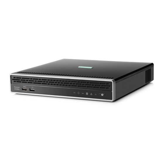
HPE ProLiant EC200a Managed
Hybrid Server
User Guide
Abstract
This document is for the person who installs, administers, and troubleshoots servers and storage systems. Hewlett Packard Enterprise
assumes that you are qualified in the servicing of computer equipment and trained in recognizing hazards in products with hazardous
energy levels.
Part Number: 856709-002
September 2016
Edition: 2
Advertisement
Table of Contents

Related Manuals for HP ProLiant EC200a


Summary of Contents for HP ProLiant EC200a
-
Page 1: User Guide
HPE ProLiant EC200a Managed Hybrid Server User Guide Abstract This document is for the person who installs, administers, and troubleshoots servers and storage systems. Hewlett Packard Enterprise assumes that you are qualified in the servicing of computer equipment and trained in recognizing hazards in products with hazardous energy levels. - Page 2 © Copyright 2016 Hewlett Packard Enterprise Development LP The information contained herein is subject to change without notice. The only warranties for Hewlett Packard Enterprise products and services are set forth in the express warranty statements accompanying such products and services. Nothing herein should be construed as constituting an additional warranty.
-
Page 3: Table Of Contents
Contents Component identification .......................... 5 Front panel components ............................5 Front panel LEDs and button ........................... 5 Front panel LED power fault codes ....................... 6 Rear panel components ............................6 QR code label ..............................7 Rear panel LEDs and button ............................ 7 Recovery mode ............................. - Page 4 Install the server in the wall mount ......................32 Installing the server on the storage expansion unit ....................34 Install the server on the storage expansion unit ..................35 Prepare the server for operation after storage expansion unit installation ..........36 Installing the communication board ........................
-
Page 5: Component Identification
Component identification Front panel components Item Description USB 3.0 connector USB 2.0 connector Front panel LEDs and button Item Description Status UID LED Solid blue = Activated Flashing blue = Remote management or firmware upgrade in progress Off = Deactivated Wi-Fi LED Reserved WAN LED... -
Page 6: Front Panel Led Power Fault Codes
Power On/Standby Solid white = System on button and system Flashing white = Performing power on sequence power LED Solid red = System in standby Flashing red = Unsuccessful power on sequence. When the 120 W power adapter is connected to a server that is attached to a storage expansion unit, the system power LED flashes red. -
Page 7: Qr Code Label
Item Description Video connector To reduce the risk of electric shock, fire, or damage to the equipment, only devices that are made of fire-retardant material can be connected to this video connector (VGA). Kensington security slot Dedicated iLO management connector LAN connector WAN connector * These connectors are present in the communication board option... -
Page 8: Recovery Mode
Recovery mode Do not initiate recovery mode unless directed by HPE ProLiant Easy Connect Support (https://support.prolianteasyconnect.com). During recovery mode, the system will first attempt to perform a graceful shutdown of the operating system (soft reset). If the soft reset attempt fails, the system will proceed to a hard reset. Bottom components Item Description... -
Page 9: System Board Components
System board components Item Description System battery Reserved Fan connector Channel 1 DIMM slot Channel 2 DIMM slot Drive 2 SATA connector Drive 1 SATA connector Communication board connector Drive 2 power connector System maintenance switch Ambient temperature sensor connector Drive 1 power connector System maintenance switch Do not change any of the system maintenance switch settings unless directed by HPE ProLiant Easy... -
Page 10: Drive Numbering
Position Default Function Reserved Off = Power-on password is enabled. On = Power-on password is disabled. Off = No function On = ROM reads system configuration as invalid. — Reserved S7, S8, S9, S10, S11, and S12 You can access the redundant ROM by setting S1, S5, and S6 to On. When the system maintenance S6 switch is set to the On position, the system will erase all system configuration settings from both CMOS and NVRAM on the next reboot. -
Page 11: Kensington Security Slot Locations
Kensington security slot locations • Kensington security slot for a server in the desktop position—Use a Kensington cable lock. • Kensington security slot for a server installed in the cradle—Use a Kensington cable lock. • Kensington security slot in the wall mount—Use a Kensington noncable lock or a cable lock that includes a wall mount anchor. -
Page 12: Fan Location
• Kensington security slot in the storage expansion unit—Use a Kensington cable lock. Fan location • Fan location in the server Component identification 12... - Page 13 • Fan location in the storage expansion unit Component identification 13...
-
Page 14: Operations
Operations Server warnings and cautions WARNING: To reduce the risk of personal injury, electric shock, or damage to the equipment, remove the power cord to remove power from the server. Pressing the Power On/Standby button does not shut off system power completely. Portions of the power supply and some internal circuitry remain active until AC power is removed. -
Page 15: Power Down Procedure
Verify that the system power LEDs on both servers are white ("Front panel LEDs and button" on page 5). Power down procedure Prerequisites Notify Hewlett Packard Enterprise of any planned power down to ensure the orderly shutdown of server services. To contact Hewlett Packard Enterprise, see the HPE ProLiant Easy Connect Support (https://support.prolianteasyconnect.com). -
Page 16: Prepare The Server For Hardware Installation Or Removal
Prepare the server for hardware installation or removal Verify that the server data has been recently backed up. Do one of the following: Power down a single-server system (on page 15). Power down a clustered system (on page 15). Disconnect the power cord from the AC source, and then disconnect the power adapter from the server. -
Page 17: Remove The Server From The Wall Mount
Remove the server from the cradle. Remove the server from the wall mount Open the wall mount latch. Remove the server from the wall mount. Remove the server from the storage expansion unit Before you perform this procedure, make sure that you have a No. 2 Phillips screwdriver available. Hold the top side of the server and the bottom side of the storage expansion unit, and then carefully turn the assembly over to access the bottom side of the storage expansion unit. -
Page 18: Remove The Access Panel
Push the latch back in place. Return the assembly to an upright position. Remove the server from the storage expansion unit. Remove the access panel Before you perform this procedure, make sure that you have a No. 2 Phillips screwdriver available. Loosen the captive screws. -
Page 19: Install The Access Panel
Slide the access panel toward the front of the server, and then lift it from the server. Install the access panel Before you perform this procedure, make sure that you have a No. 2 Phillips screwdriver available. Slide the access panel toward the rear of the server. Tighten the captive screws. -
Page 20: Setup
Setup Optimum environment When installing the server, select a location that meets the environmental standards described in this section. Operating environmental requirements The server may be located in an office space or a purpose-made equipment room. The location must: • Comply with local health and safety regulations. -
Page 21: Electrical Grounding Requirements
When installing more than one server, you might need to use additional power distribution devices to provide power to all devices safely. Observe the following guidelines: • Balance the server power load between available AC supply branch circuits. • Do not allow the overall system AC current load to exceed 80% of the branch circuit AC current rating. -
Page 22: Identify The Contents Of The Server Shipping Carton
• Confirm that the installation engineer understands how to integrate the server into the user network, in particular from an IP addressing perspective and from a domain perspective. • Prepare Ethernet cables of an appropriate length for each of the LAN, WAN, and remote management (iLO) connections. -
Page 23: Hardware Options Installation
Hardware options installation Introduction If more than one option is being installed, read the installation instructions for all the hardware options and identify similar steps to streamline the installation process. WARNING: To reduce the risk of personal injury from hot surfaces, allow the drives and the internal system components to cool before touching them. -
Page 24: Installing The Server In The Wall Mount
Attach the server to the cradle: Insert the two hooks on the right side of the cradle into the corresponding openings on the bottom of the server. Align and insert the two posts on the cradle into the corresponding openings on the bottom of the server. -
Page 25: Wall Mount Orientation
Wall mount orientation This wall mount can only be installed in a single orientation—the retention latch on the top side of the wall mount must be facing upward. When the server is installed on the wall mount, the server rear panel will be facing upward as well. - Page 26 Use a level to ensure that the mounting positions are perfectly straight. Install the wall mount anchors on the left pilot holes: On the left mounting positions, use a drill to bore pilot holes with a diameter of 7.920 mm (0.312 in) and depth of at least 50.8 mm (2.00 in).
- Page 27 Install the wall mount screws halfway through into the top mounting positions. Install the wall mount. Hardware options installation 27...
- Page 28 Install the wall mount screws halfway through into the bottom mounting positions. Completely tighten all four wall mount screws. Install the wall mount on a brick/concrete wall Mark all four screw mounting positions: Hardware options installation 28...
- Page 29 Mark the screw mounting positions. Use a level to ensure that the mounting positions are perfectly straight. Install the wall mount anchors: On all four mounting positions, use a drill to bore pilot holes with a diameter of 7.920 mm (0.312 in) and depth of at least 50.8 mm (2.00 in).
- Page 30 Use a hammer to install the anchors in the pilot holes. Install the wall mount screws halfway through into the top mounting positions. Hardware options installation 30...
- Page 31 Install the wall mount. Install the wall mount screws halfway through into the bottom mounting positions. Hardware options installation 31...
-
Page 32: Install The Server In The Wall Mount
Completely tighten all four wall mount screws. Install the server in the wall mount If the power source location is lower than the wall mount, do the following to position the power adapter inside the wall mount: Route the power cord through the bottom opening of the wall mount. Place the power adapter inside the wall mount. - Page 33 Route the power and adapter cords through the top opening of the wall mount, with the adapter cord grommet extended out of the opening. For cable management purposes, secure the extra length of the adapter cord that is not extended out of the wall mount inside the wall mount.
-
Page 34: Installing The Server On The Storage Expansion Unit
— Installing the server in the wall mount when the power source location is higher than the wall mount. Installing the server on the storage expansion unit This storage expansion unit supports four LFF low-profile SATA drives. Process overview for installing the storage expansion unit together with a new server: HPE configures the availability and allocation of the drives installed in the storage expansion unit. -
Page 35: Install The Server On The Storage Expansion Unit
Affected service components might briefly restart during this step. Install the server on the storage expansion unit Before you perform this procedure, make sure that you have a No. 2 Phillips screwdriver available. Remove the cover from the server dock connector. Keep the cover for future use. -
Page 36: Prepare The Server For Operation After Storage Expansion Unit Installation
Tighten the captive screws. Push the latch back in place. Return the assembly to an upright position. Prepare the server for operation after storage expansion unit installation If removed, install the Kensington security lock. For more information, see the Kensington security lock documentation. Connect all peripheral cables to the server. -
Page 37: Installing The Communication Board
Determine the status of the storage expansion unit drives from the drive LED definitions ("Front panel LEDs and button" on page 5). Installing the communication board For a high-availability solution, the communication board must be installed into each server deployed into a clustered configuration. - Page 38 Retain the screws for later use. Remove the RJ-45 port blank. Retain the blank for future use. Hardware options installation 38...
- Page 39 Align the rear screw holes of the communication board to the middle frame, and then press down on the front end of the board until it clicks into place. Install the RJ-45 port spacer. Ensure that the spacer is flush against the rear panel surface. Hardware options installation 39...
-
Page 40: Prepare The Server For Setup
Align the rear screw holes of the RJ-45 port bracket to the middle frame, and then install the screws according to the numbering indicated on the bracket. Install the communication board screws. Prepare the server for setup Install the access panel (on page 19). If the server was removed from the cradle, wall mount, or storage expansion unit, do one of the following: Install the server in the cradle (on page 23). - Page 41 For detailed initial setup instructions for single-server or HA server deployment, go to the HPE ProLiant Easy Connect Support Portal (https://support.prolianteasyconnect.com). Hardware options installation 41...
-
Page 42: Cabling
Cabling Cabling overview This section provides guidelines that help you make informed decisions about cabling the server and hardware options to optimize performance. CAUTION: When routing cables, always be sure that the cables are not in a position where they can be pinched or crimped. Drive cabling Item Description... -
Page 43: Fan Cabling
Fan cabling Ambient temperature sensor cabling Cabling 43... -
Page 44: Software And Configuration Utilities
Software and configuration utilities Product QuickSpecs For more information about product features, specifications, options, configurations, and compatibility, see the product QuickSpecs on the Hewlett Packard Enterprise website (http://www.hpe.com/info/qs). Hewlett Packard Enterprise cloud management platform The cloud management platform integrated in the HPE ProLiant Easy Connect Managed Hybrid servers allows Hewlett Packard Enterprise to provide server monitoring and management services. -
Page 45: Monitoring Console
Monitoring Console The Monitoring Console allows IT experts to monitor the state of one or more servers, including the following: • Results of numerous automated tests • Log records for hardware, software, and services For more information on this console, see the HPE ProLiant Easy Connect Monitoring Consoles Guide on the Hewlett Packard Enterprise website (http://www.hpe.com/support/EC-MCG). -
Page 46: Usb Support
*Scan the QR code on the screen to access online help for the UEFI System Utilities and UEFI Shell. Default configuration settings are applied to the server at one of the following times: • Upon the first system power-up • After defaults have been restored Default configuration settings are sufficient for typical server operations;... - Page 47 When changing the schedule, the user must accept responsibility for the resulting interim risks to the reliability of the server and the availability, privacy, and integrity of their data. Urgent software patches and security updates are not subject to the predetermined schedule. Always apply urgent software patches and security updates as soon as possible after Hewlett Packard Enterprise identifies, resolves, and tests the patches and updates.
-
Page 48: Troubleshooting
Troubleshooting Troubleshooting resources The HPE ProLiant Easy Connect Managed Hybrid Server Troubleshooting Guide (http://www.hpe.com/support/EC-TSG) provides procedures for resolving common problems and comprehensive courses of action for fault isolation and identification, issue resolution, and software maintenance. For the latest server support information, see the Hewlett Packard Enterprise ProLiant Easy Connect Support Portal (https://support.prolianteasyconnect.com). -
Page 49: System Battery Replacement
System battery replacement System battery information The server contains an internal lithium manganese dioxide, a vanadium pentoxide, or an alkaline battery that provides power to the real-time clock. If this battery is not properly handled, a risk of the fire and burns exists. - Page 50 Retain the screws for later use. Remove the RJ-45 port spacer. Retain the blank for future use. System battery replacement 50...
- Page 51 Remove the communication board. Replace the system battery (on page 53). If removed, install the communication board. Align the rear screw holes of the communication board to the middle frame, and then press down on the front end of the board until it clicks into place. Install the RJ-45 port spacer.
- Page 52 Ensure that the spacer is flush against the rear panel surface. Align the rear screw holes of the RJ-45 port bracket to the middle frame, and then install the screws according to the numbering indicated on the bracket. System battery replacement 52...
-
Page 53: Replace The System Battery
Install the communication board screws. Install the access panel (on page 19). If the server was removed from the cradle, wall mount, or storage expansion unit, do one of the following: Install the server in the cradle (on page 23). Install the server in the wall mount (on page 32). - Page 54 Slightly push the metal tab, then install the system battery in the socket. For more information about battery replacement or proper disposal, contact an authorized reseller or an authorized service provider. System battery replacement 54...
-
Page 55: Warranty And Regulatory Information
Warranty and regulatory information Warranty information HPE ProLiant and x86 Servers and Options (http://www.hpe.com/support/ProLiantServers-Warranties) HPE Enterprise Servers (http://www.hpe.com/support/EnterpriseServers-Warranties) HPE Storage Products (http://www.hpe.com/support/Storage-Warranties) HPE Networking Products (http://www.hpe.com/support/Networking-Warranties) Regulatory information Safety and regulatory compliance For important safety, environmental, and regulatory information, see Safety and Compliance Information for Server, Storage, Power, Networking, and Rack Products, available at the Hewlett Packard Enterprise website (http://www.hpe.com/support/Safety-Compliance-EnterpriseProducts). -
Page 56: Gs Gloss Declaration
Local representative information Kazakh: • Russia: • Belarus: • Kazakhstan: Manufacturing date: The manufacturing date is defined by the serial number. CCSYWWZZZZ (serial number format for this product) Valid date formats include: • YWW, where Y indicates the year counting from within each new decade, with 2000 as the starting point;... -
Page 57: Electrostatic Discharge
Electrostatic discharge Preventing electrostatic discharge To prevent damaging the system, be aware of the precautions you must follow when setting up the system or handling parts. A discharge of static electricity from a finger or other conductor may damage system boards or other static-sensitive devices. This type of damage may reduce the life expectancy of the device. -
Page 58: Specifications
Specifications Environmental specifications Specification Value — Temperature range 10°C to 35°C (50°F to 95°F) Operating -30°C to 65°C (-22°F to 149°F) Nonoperating — Relative humidity (noncondensing) Maximum wet bulb temperature of 28°C Operating (82.4°F) = 10% to 90% Maximum wet bulb temperature of 38.7°C Nonoperating (101.7°F) = 0% to 95% All temperature ratings shown are for sea level. -
Page 59: Support And Other Resources
Support and other resources Accessing ProLiant Easy Connect Support For the latest server support information, see the Hewlett Packard Enterprise ProLiant Easy Connect Support Portal (https://support.prolianteasyconnect.com). Accessing Hewlett Packard Enterprise Support • For live assistance, go to the Contact Hewlett Packard Enterprise Worldwide website (http://www.hpe.com/assistance). - Page 60 • Optional—Parts for which customer self repair is optional. These parts are also designed for customer self repair. If, however, you require that Hewlett Packard Enterprise replace them for you, there may or may not be additional charges, depending on the type of warranty service designated for your product.
- Page 61 Pour plus d'informations sur le programme CSR de Hewlett Packard Enterprise, contactez votre Mainteneur Agrée local. Pour plus d'informations sur ce programme en Amérique du Nord, consultez le site Web Hewlett Packard Enterprise (http://www.hpe.com/support/selfrepair). Riparazione da parte del cliente Per abbreviare i tempi di riparazione e garantire una maggiore flessibilità nella sostituzione di parti difettose, i prodotti Hewlett Packard Enterprise sono realizzati con numerosi componenti che possono essere riparati direttamente dal cliente (CSR, Customer Self Repair).
- Page 62 Enterprise vornehmen lassen möchten, können bei diesem Service je nach den für Ihr Produkt vorgesehenen Garantiebedingungen zusätzliche Kosten anfallen. HINWEIS: Einige Hewlett Packard Enterprise Teile sind nicht für Customer Self Repair ausgelegt. Um den Garantieanspruch des Kunden zu erfüllen, muss das Teil von einem Hewlett Packard Enterprise Servicepartner ersetzt werden.
- Page 63 Enterprise se hará cargo de todos los gastos de envío y devolución de componentes y escogerá la empresa de transporte que se utilice para dicho servicio. Para obtener más información acerca del programa de Reparaciones del propio cliente de Hewlett Packard Enterprise, póngase en contacto con su proveedor de servicios local.
- Page 64 • Obrigatória—Peças cujo reparo feito pelo cliente é obrigatório. Se desejar que a Hewlett Packard Enterprise substitua essas peças, serão cobradas as despesas de transporte e mão-de-obra do serviço. • Opcional—Peças cujo reparo feito pelo cliente é opcional. Essas peças também são projetadas para o reparo feito pelo cliente.
- Page 65 Support and other resources 65...
- Page 66 Support and other resources 66...
- Page 67 Support and other resources 67...
-
Page 68: Acronyms And Abbreviations
Acronyms and abbreviations Canadian Standards Association Customer Self Repair high availability International Electrotechnical Commission Integrated Lights-Out large form factor managed service provider NVRAM nonvolatile memory power distribution unit POST Power-On Self-Test QR code quick response code SATA serial ATA solid-state device Acronyms and abbreviations 68... - Page 69 UEFI Unified Extensible Firmware Interface unit identification uninterruptible power system Acronyms and abbreviations 69...
-
Page 70: Documentation Feedback
Documentation feedback Hewlett Packard Enterprise is committed to providing documentation that meets your needs. To help us improve the documentation, send any errors, suggestions, or comments to Documentation Feedback (mailto:docsfeedback@hpe.com). When submitting your feedback, include the document title, part number, edition, and publication date located on the front cover of the document. For online help content, include the product name, product version, help edition, and publication date located on the legal notices page. -
Page 71: Index
Index drive SATA-power Y-cable, cabling 42 drives, adding 34 drives, determining status of 5 access panel, installing 19 access panel, removing 18 activation code 44 airflow requirements 20, 21 electrical grounding requirements 21 ambient temperature 20, 58 electrostatic discharge 57 ambient temperature sensor cable 43 environmental requirements 20, 58 authorized reseller 57, 59... - Page 72 LED, drive activity 5 recovery mode 8 LED, health 5 redundant ROM 9, 46 LED, LAN 5 registering the server 22 LED, system power 5 regulatory compliance information 55 LED, UID 5 requirements, airflow 21 LED, unit identification (UID) 5 requirements, electrical grounding 21 LED, WAN 5 requirements, environmental 20...
- Page 73 ventilation 20 video connector 6 wall mount, determining location 25 wall mount, installing 24, 32 wall mount, removing server from 17 WAN LED 5 WAN, connector 6 warnings 14 warranty information 55 website, Hewlett Packard Enterprise 59 website, HPE ProLiant Easy Connect Support Portal 59 weight 58 Wi-Fi LED 5...