
Related Manuals for HP FlexFabric 5950 Series


Summary of Contents for HP FlexFabric 5950 Series
-
Page 1: Installation Guide
HPE FlexFabric 5950 Switch Series Installation Guide Part number: 5200-2233b Document version: 6W102-20170125... - Page 2 © Copyright 2017 Hewlett Packard Enterprise Development LP The information contained herein is subject to change without notice. The only warranties for Hewlett Packard Enterprise products and services are set forth in the express warranty statements accompanying such products and services. Nothing herein should be construed as constituting an additional warranty. Hewlett Packard Enterprise shall not be liable for technical or editorial errors or omissions contained herein.
-
Page 3: Table Of Contents
Contents Preparing for installation ····································································1 Safety recommendations ··············································································································· 1 Examining the installation site········································································································· 2 Temperature/humidity ············································································································ 2 Cleanliness ·························································································································· 2 EMI ···································································································································· 3 Laser safety ························································································································· 3 Installation tools ··························································································································· 3 Installation accessories ················································································································· 4 Installing the switch ··········································································7 Installing the switch in a 19-inch rack ······························································································· 8 Installation accessories ··········································································································... - Page 4 Configuration terminal display problems ························································································· 43 No display ·························································································································· 43 Garbled display ··················································································································· 43 Appendix A Chassis views and technical specifications ·························· 44 Chassis views ··························································································································· 44 HPE 5950 32QSFP28 ·········································································································· 44 HPE 5950 48SFP28 8QSFP28 ······························································································ 45 HPE 5950 4-slot ·················································································································· 46 Technical specifications ··············································································································...
-
Page 5: Preparing For Installation
Preparing for installation The HPE FlexFabric 5950 Switch Series includes the models and provides power supplies and fan trays in Table Table 1 HPE FlexFabric 5950 Switch Series models and power supplies Product code HPE description Alias HPE FlexFabric 5950 Switch Series JH321A HPE FlexFabric 5950 32QSFP28 Switch HPE 5950 32QSFP28... -
Page 6: Examining The Installation Site
• Do not place the switch on an unstable case or desk. The switch might be severely damaged in case of a fall. • Ensure good ventilation of the equipment room and keep the air inlet and outlet vents of the switch free of obstruction. -
Page 7: Emi
Substance Concentration limit (particles/m NOTE: Dust diameter ≥ 5 μm The equipment room must also meet limits on salts, acids, and sulfides to eliminate corrosion and premature aging of components, as shown in Table Table 3 Harmful gas limits in the equipment room Maximum concentration (mg/m 0.006 0.05... -
Page 8: Installation Accessories
• Marker. Installation accessories Table 4 Installation accessories Product code Description Quantity Applicable models 1 U mounting bracket kit (including one pair of mounting brackets and eight M4 countersunk screws) 5066-0850 1 kit HPE 5950 32QSFP28 Mounting brackets for the HPE 5950 48SFP28 8QSFP28 switch 5190-0719 1 kit... - Page 9 Product code Description Quantity Applicable models 2U short slide rail kit (including one pair of slide rails and four M4 countersunk screws) 5185-8684 1 kit HPE 5950 4-slot M6 screw and floating nut User All HPE 5950 switches supplied Grounding cable 5184-6723 All HPE 5950 switches Grounding screw...
- Page 10 Product code Description Quantity Applicable models SFP/SFP+ dust plug 5185-8722 Optional All HPE 5950 switches QSFP28 dust plug 5187-9022 Optional All HPE 5950 switches...
-
Page 11: Installing The Switch
Installing the switch CAUTION: Keep the tamper-proof seal on a mounting screw on the chassis cover intact, and if you want to open the chassis, contact Hewlett Packard Enterprise Support for permission. Otherwise, Hewlett Packard Enterprise shall not be liable for any consequence caused thereby. Figure 1 Hardware installation flow Start Install the switch... -
Page 12: Installing The Switch In A 19-Inch Rack
Installing the switch in a 19-inch rack IMPORTANT: To install the switch in a 19-inch rack, make sure the rack has a minimum depth of 1000 mm (39.37 in) so that the rack door can be closed easily. Installation accessories Table 5 Installation accessories Switch Mounting brackets... - Page 13 Figure 4 Mounting brackets provided with the HPE 5950 4-slot switch (1) Cable management bracket (2) Mounting bracket Figure 5 1U short slide rail and chassis rail (1) Chassis rail (2) Short slide rail Figure 6 1U long slide rail and chassis rail (1) Chassis rail (2) Long slide rail...
-
Page 14: Mounting Brackets, Chassis Rails, And Grounding Cable Installation Positions
Figure 7 2U slide rail and chassis rail (1) Chassis rail (2) Slide rail Mounting brackets, chassis rails, and grounding cable installation positions The switch has one mounting position near the network ports and one mounting position near the power supplies for mounting brackets. The HPE 5950 4-slot switch provides three grounding points: primary grounding point (with a grounding sign), auxiliary grounding point 1, and auxiliary grounding point 2. -
Page 15: Installation Methods
Figure 9 Mounting brackets and grounding cable installation positions on the HPE 5950 48SFP28 8QSFP28 (1) Power supply-side mounting position (2) Primary grounding point (3) Auxiliary grounding point (4) Port-side mounting position Figure 10 Mounting brackets and grounding cable installation positions on the HPE 5950 4-slot switch (1) Auxiliary grounding point 2 (2) Power supply-side mounting position... -
Page 16: Rack-Mounting The Switch By Using Mounting Brackets And Rack Mounting Rail Kit
NOTE: If a rack shelf is available, you can put the switch on the rack shelf, slide the switch to an appropriate location, and attach the switch to the rack with the mounting brackets. To rack-mount the switch, the distance between the front and rear posts of the rack must meet the requirements described in Table Table 6 Distance requirements between the front and rear rack posts... - Page 17 Figure 12 Attaching the mounting brackets and chassis rails to the HPE 5950 32QSFP28 switch (power supply-side mounting position for the mounting brackets) Figure 13 Attaching the mounting brackets and chassis rails to the HPE 5950 48SFP28 8QSFP28 switch (power supply-side mounting position for the mounting brackets) Figure 14 Attaching the mounting brackets and chassis rails to the HPE 5950 4-slot switch (power supply-side mounting position for the mounting brackets)
- Page 18 Figure 15 Attaching the mounting brackets and chassis rails to the HPE 5950 32QSFP28 switch (network port-side mounting position for the mounting brackets) Figure 16 Attaching the mounting brackets and chassis rails to the HPE 5950 48SFP28 8QSFP28 switch (network port-side mounting position for the mounting brackets) Figure 17 Attaching the mounting brackets and chassis rails to the HPE 5950 4-slot switch (network port-side mounting position for the mounting brackets)
- Page 19 Connecting the grounding cable to the chassis CAUTION: The primary grounding point and auxiliary grounding point are located on the left panel of the chassis. If you use one of these grounding points, you must connect the grounding cable to the grounding point before you mount the switch in the rack.
- Page 20 Figure 19 Installing the 1U slide rails Mounting the switch in the rack This task requires two people. To mount the switch in the rack: Wear an ESD wrist strap and make sure it makes good skin contact and is reliably grounded. Verify that the mounting brackets and chassis rails have been securely attached to the switch chassis.
- Page 21 Figure 20 Mounting the HPE 5950 32QSFP28 switch in the rack (power supply-side mounting position for the mounting brackets) Figure 21 Mounting the HPE 5950 32QSFP28 switch in the rack (Port-side mounting position for the mounting brackets)
- Page 22 Figure 22 Mounting the HPE 5950 4-slot switch in the rack (power supply-side mounting position for the mounting brackets) Figure 23 Mounting the HPE 5950 4-slot switch in the rack (Port-side mounting position for the mounting brackets) NOTE: To rack-mount the HPE 5950 4-slot switch by using 2U high mounting brackets and slide rails, use two screws and two cage nuts to attach each mounting bracket to the rack.
-
Page 23: Grounding The Switch
Grounding the switch WARNING! Correctly connecting the switch grounding cable is crucial to lightning protection and EMI protection. The power input end of the switch has a noise filter, whose central ground is directly connected to the chassis to form the chassis ground (commonly known as PGND). You must securely connect this chassis ground to the earth so the faradism and leakage electricity can be safely released to the earth to minimize EMI susceptibility of the switch. -
Page 24: Grounding The Switch By Using The Ac Power Cord
Figure 24 Connecting the grounding cable to a grounding strip (1) Hex nut (2) Ring terminal (3) Grounding post (4) Grounding strip Grounding the switch by using the AC power cord If the installation site does not have grounding strips, you can ground an AC-powered switch through the protective earth (PE) wire of the power cord. -
Page 25: Installing/Removing Fan Trays
Figure 25 Grounding the switch through the PE wire of the AC power cord (1) Three-wire AC power cord (2) Rear panel NOTE: As a best practice to guarantee the grounding effect, use the grounding cable provided with the switch to connect to the grounding strip in the equipment room. Installing/removing fan trays CAUTION: The switch has multiple fan tray slots. -
Page 26: Installing A Fan Tray
Installing a fan tray CAUTION: To prevent damage to the fan tray or the connectors on the backplane, insert the fan tray gently. If you encounter a hard resistance while inserting the fan tray, pull out the fan tray and insert it again. IMPORTANT: Before powering on the switch, make sure the fan tray airflow direction and the preferred airflow direction of the switch are the same. -
Page 27: Installing/Removing Power Supplies
Figure 27 Removing an X712 Bck(pwr)-Frt(prt) HV2 fan tray Installing/removing power supplies WARNING! • To avoid bodily injury and device damage, strictly follow the procedures in Figure 28 Figure 29Figure 29 to install and remove a power supply. • Provide a separate circuit breaker for each power supply. The HPE 5950 32QSFP28 and HPE 5950 48SFP28 8QSFP28 switches each have two power supply slots.The HPE 5950 4-slot switch has four power supply slots. -
Page 28: Removing A Power Supply
To install a power supply: Wear an ESD wrist strap and make sure it makes good skin contact and is reliably grounded. Remove the filler panel, if any, from the target power supply slot, as shown in Figure Figure 30 Removing a filler panel Unpack the power supply and verify that the power supply model is correct. - Page 29 The 650W AC power supply and 650W DC power supply removal procedure is the same on the HPE 5950 switches. The figures in this section use the HPE 5950 32QSFP28 switch as an example. To remove a power supply: Wear an ESD wrist strap and make sure it makes good skin contact and is reliably grounded. Squeeze the tabs on the power cord connector with your thumb and forefinger, and pull the connector out to remove the power cord, as shown in Figure...
-
Page 30: Connecting The Power Cords
Figure 33 Removing the power supply (1) Pivot the latch to the right with your thumb (2) Pull the power supply out Connecting the power cords WARNING! Provide a circuit breaker for each power input. When you connect a power cord, make sure the circuit breaker is switched off. -
Page 31: Connecting A Dc Power Cord
Connecting a DC power cord Align the power cord plug with the power receptacle on the power supply, and insert the plug into the receptacle (see Figure 35). The plug and receptacle are foolproof. If you cannot insert the plug into the receptacle, re-orient the plug rather than use excessive force to push it in. - Page 32 Figure 36 Removing the filler panel from the expansion slot Keep the removed filler panel secure for future use. Unpack the expansion card. Figure 37 LSWM18CQ interface card (1) Ejector lever (2) Latch Press the latch on the expansion card to release the ejector lever. Insert the expansion card slowly into the slot along the guide rails, as shown by callout 1 in Figure Rotate inward the ejector lever as shown by callout 2 in...
-
Page 33: Verifying The Installation
Removing an expansion card CAUTION: • Before you remove an expansion card, remove the cable from it to avoid cable damage. • If you are not to install a new expansion card after removing the original one, install the filler panel in the slot to prevent dust and ensure good ventilation in the device. -
Page 34: Accessing The Switch For The First Time
Accessing the switch for the first time Setting up the configuration environment You can access the switch through the serial console port or the mini USB console port. As a best practice, use the serial console port to access the switch. To access the switch through the mini USB console port, you need to prepare a mini USB console cable yourself. -
Page 35: Connecting The Mini Usb Console Cable
RJ-45 Signal DB-9 Signal To connect a terminal (for example, a PC) to the switch by using the serial console cable: Connect the DB-9 female connector of the serial console cable to the serial port of the PC. Connect the RJ-45 connector to the serial console port of the switch. NOTE: •... - Page 36 Figure 42 Device Driver Installation Wizard Click Continue Anyway if the following dialog box appears. Figure 43 Software Installation Click Finish.
-
Page 37: Setting Terminal Parameters
Figure 44 Completing the device driver installation wizard Setting terminal parameters To configure and manage the switch through the console port, you must run a terminal emulator program, TeraTermPro or PuTTY, on your configuration terminal. You can use the emulator program to connect a network device, a Telnet site, or an SSH site. - Page 38 Power on the switch. During the startup process, you can access BootWare menus to perform tasks such as software upgrade and file management. The BootWare interface and menu options vary by software version. For more information about BootWare menu options, see the software-matching release notes for the device.
-
Page 39: Setting Up An Irf Fabric
Setting up an IRF fabric You can use HPE IRF technology to connect and virtualize multiple switches into a large virtual switch called an "IRF fabric" for flattened network topology, and high availability, scalability, and manageability. IRF fabric setup flowchart Figure 45 IRF fabric setup flowchart Start Plan IRF fabric setup... -
Page 40: Planning Irf Fabric Setup
Step Description Install IRF member "Installing the switch in a 19-inch rack". switches. Connect ground wires "Grounding the switch" and "Connecting the power cords." and power cords. Power on the switches. Configure basic IRF See HPE FlexFabric 5950 Switch Series IRF Configuration Guide. settings. -
Page 41: Planning Irf Topology And Connections
Planning IRF topology and connections You can create an IRF fabric in daisy chain topology, or more reliably, ring topology. In ring topology, the failure of one IRF link does not cause the IRF fabric to split as in daisy chain topology. Rather, the IRF fabric changes to a daisy chain topology without interrupting network services. -
Page 42: Identifying Physical Irf Ports On The Member Switches
Figure 47 IRF fabric in ring topology IRF-port2 IRF-port1 IRF-port2 IRF-port1 IRF-port1 IRF-port2 You can set up IRF links between HPE 5950 switches as follows: • Use a QSFP28 module and fiber or a QSFP28 cable to connect QSFP28 ports for a 100-GE IRF physical connection. -
Page 43: Planning The Cabling Scheme
range, the ports are grouped by port number in order, starting from the lowest number. Each group contains four ports. • On an LSWM124TG2H (JH450A) module, the ports numbered 1 to 24 are grouped by port number in order, starting from the lowest number. Each group contains four ports. •... -
Page 44: Configuring Basic Irf Settings
Figure 49 IRF fabric topology Connecting the IRF member switches in a ToR solution You can install IRF member switches in different racks side by side to deploy a top of rack (ToR) solution. Figure 50 shows an example for connecting four top of rack IRF member switches by using QSFP28 network cables. -
Page 45: Accessing The Irf Fabric To Verify The Configuration
Use cables to connect the IRF member switches as planned. Accessing the IRF fabric to verify the configuration To verify the basic functionality of the IRF fabric after you finish configuring basic IRF settings and connecting IRF ports: Log in to the IRF fabric through the console port of any member switch. Create a Layer 3 interface, assign it an IP address, and make sure the IRF fabric and the remote network management station can reach each other. -
Page 46: Maintenance And Troubleshooting
Maintenance and troubleshooting Power supply failure Symptom The power supply status LED on a power supply is not steady green (active state) or flashing green (standby state) For more information about the LEDs on a power supply, see HPE A58x0AF 650W AC (JC680A) & 650W DC (JC681A) Power Supplies User Guide or HPE FlexFabric Switch 650W 48V Hot Plug NEBS Compliant DC Power Supply (JH336A) User Guide. -
Page 47: Solution
Solution "Installing/removing fan trays" to replace the fan tray. If the problem persists, contact Hewlett Packard Enterprise Support. Configuration terminal display problems No display Symptom The configuration terminal displays nothing when the switch is powered on. Solution To resolve the problem: Verify that the power system is operating correctly. -
Page 48: Appendix A Chassis Views And Technical Specifications
Appendix A Chassis views and technical specifications Chassis views HPE 5950 32QSFP28 Figure 51 Front panel (1) QSFP28 port (2) QSFP28 port LED (3) SFP+ port (4) SFP+ port LED Figure 52 Rear panel (1) Mini USB console port (2) Copper management Ethernet port (3) Serial console port (4) USB port (5) Fan tray 1... -
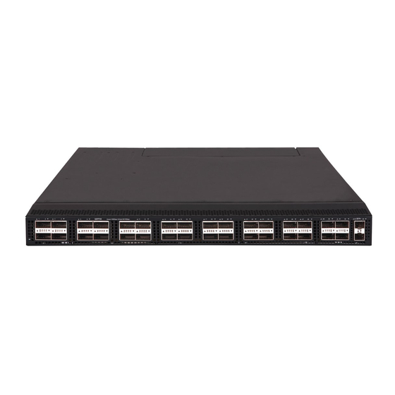
Page 49: Hpe 5950 48Sfp28 8Qsfp28
The HPE 5950 switches come with the six fan tray slots empty. You must install six fan trays of the same model for the switch. In Figure 52, six X712 Bck(pwr)-Frt(prt) HV2 fan trays are installed in the fan tray slots. Figure 53 Left panel (1) Primary grounding point (2) Auxiliary grounding point... -
Page 50: Hpe 5950 4-Slot
The HPE 5950 48SFP28 8QSFP28 switch comes with power supply slot PWR1 empty and power supply slot PWR2 installed with a filler panel. You can install one or two power supplies for the switch as needed. In Figure 55, two 650W AC power supplies are installed in the power supply slots. The HPE 5950 48SFP28 8QSFP28 switch comes with the five fan tray slots empty. - Page 51 Figure 58 Rear panel (1) Mini USB console port (2) Copper management Ethernet port (3) Serial console port (4) USB port (5) SFP port (6) SFP port LED (7) Fan tray 1 (8) Fan tray 2 (9) Grounding screw (auxiliary grounding point 2) (10) Power Supply 4 (11) Power Supply 3 (12) Power Supply 2...
-
Page 52: Technical Specifications
Technical specifications Table 9 Technical specifications HPE 5950 48SFP28 Item HPE 5950 32QSFP28 HPE 5950 4-slot 8QSFP28 Dimensions 43.6 × 440 × 540 mm (1.72 × 43.6 × 440 × 460 mm (1.72 × 88.1 × 440 × 660 mm (3.47 × (H ×... - Page 53 HPE 5950 48SFP28 Item HPE 5950 32QSFP28 HPE 5950 4-slot 8QSFP28 • UL60950-1 Chassis • EN60950-1 leakage • current IEC60950-1 compliance • GB4943 Melting • 650W AC power supply: 10 A @ 250 VAC current of • power 650W DC power supply: 30 A @ 250 VDC supply fuse Operating temperatur...
-
Page 54: Appendix B Frus
Appendix B FRUs The switch uses modular design. Table 10 describes the FRUs available for the switch.. Table 10 FRUs available for the switch HPE 5950 48SFP28 FRUs HPE 5950 4-slot 595032QSFP28 8QSFP28 Power supplies 650W AC power supply 650W AC power supply Fan trays HPE X712 Bck(pwr)-Frt(prt) HV2... -
Page 55: Power Supplies
Power supplies CAUTION: When the switch has power supplies in redundancy, you can replace a power supply without powering off the switch. Make sure the power supply to be replaced is powered off before you replace it. Table 11 Power supply specifications Power supply model Specifications Remarks... -
Page 56: Expansion Cards
Expansion cards The HPE 5950 4-slot switch provides four expansion slots. Select expansion cards for the switch as required. Table 13 Interface cards available for the HPE 5950 4-slot switch Interface Product Transceiver modules HPE description Alias number and code available for the ports type HPE 5950 8-port... -
Page 57: Management Ethernet Port
Table 14 Console port specifications Item Console port Mini USB console port Connector type RJ-45 USB mini-Type B Compliant EIA/TIA-232 USB 2.0 standard Transmission 9600 bps (default) to 115200 bps baud rate • Provides connection to an ASCII • Provides connection to an ASCII terminal. -
Page 58: Usb Port
USB port The switch has one OHCI-compliant USB 2.0 port that can upload and download data at a rate up to 480 Mbps. You can use this USB port to access the file system on the Flash of the switch, for example, to upload or download application and configuration files. - Page 59 Product Code Description Cable length JD097C HPE X240 10G SFP+ SFP+ 3m DA Cable 3 m (9.84 ft) JG081C HPE X240 10G SFP+ SFP+ 5m DA Cable 5 m (16.40 ft) Figure 60 SFP+ copper cable (1) Connector (2) Pull latch Table 19 10-Gigabit SFP+ optical cables available for the SFP+ ports Product Code Description...
-
Page 60: Sfp Port
Multimode Central Maximum fiber modal Product Fiber wavelength Description transmission bandwidth Code diameter (µm) distance (nm) (MHz*km) HPE X125 1G SFP LC LH40 JD061A 1310 9/125 40 km (24.86 miles) 1310nm Transceiver HPE X120 1G SFP LC LH40 JD062A 1550 9/125 40 km (24.86 miles) 1550nm... - Page 61 Table 21 QSFP28 transceiver modules available for the QSFP28 ports Cable Modal Central Maximum Product Module specifications bandwidth wavelength transmission Code description (nm) distance (µm) (MHz*km) HPE X150 100G 2000 70 m (229.66 ft) QSFP28 MPO JL274A 50/125 SR4 100m MM 4700 100 m (328.08 ft) Transceiver...
- Page 62 Table 25 QSFP+ transceiver modules available for the QSFP+ and QSFP28 ports Multimode fiber Central Fiber Maximum modal Product wavelength Description diameter transmission bandwidth Code (µm) distance (nm) (MHz*km) HPE X140 2000 100 m (328.08 ft) 40G QSFP+ JG325B 50/125 MPO SR4 4700 150 m (492.12 ft)
-
Page 63: Sfp28 Port
Figure 61 40G QSFP+/100G QSFP28 copper cable (1) Connector (2) Pull latch Figure 62 QSFP+ to 4 x SFP+ copper cable (1) Connector for a QSFP+ port (2) QSFP+ side pull latch (3) SFP+ side pull latch (4) Connector for an SFP port NOTE: •... -
Page 64: Leds
• 10-GE SFP+ copper cables in Table • 10-GE SFP+ optical cables in Table Table 29 SFP28 transceiver modules available for the SFP28 ports Central Modal Maximum Product Fiber wavelength Description bandwidth transmission Code diameter (µm) (MHz*km) distance (nm) • negotiation disabled: 30 m (98.43 ft) -
Page 65: Qsfp28 Port Led
LED mark Status Description command. The LED then flashes blue at 3 Hz. The switch is powered off or has failed to start up. QSFP28 port LED Table 32 QSFP28 port LED description LED status Description A transceiver module or network cable has been correctly installed. The port Steady green has a link and is operating at 100 Gbps. -
Page 66: Sfp Port Led
LED status Description No transceiver module or network cable has been installed or no link is present on the port. SFP port LED Table 35 SFP port LED description LED status Description A transceiver module or cable has been correctly installed. The port has a link and Steady green is operating at 1 Gbps. - Page 67 Table 38 X711 Frt(prt)-Bck(pwr) HV2 fan tray and X711 Frt(prt)-Bck(pwr) HV2 fan tray alarm LED description Status Description The fan tray is faulty. The fan tray is operating correctly or no power is being input.
-
Page 68: Appendix D Cooling System
Appendix D Cooling system CAUTION: The chassis and power supplies use separate air aisles. Make sure the two aisles are not blocked when the switch is operating. To dissipate heat timely and ensure system stability, the switch uses the front-rear air aisle cooling system. - Page 69 Figure 65 Airflow from the power supply side to the port side through the HPE 5950 48SFP28 8QSFP28 chassis (with X712 Bck(pwr)-Frt(prt) HV2 fan trays) Figure 66 Airflow from the port side to the power supply side through the HPE 5950 48SFP28 8QSFP28 chassis (with X711 Frt(prt)-Bck(pwr) HV2 fan trays) Figure 67 Airflow from the power supply side to the port side through the HPE 5950 4-slot chassis (with 5930 4-slot B(pwr) F(prt) Fan Tray fan trays)
- Page 70 Figure 68 Airflow from the port side to the power supply side through the HPE 5950 4-slot chassis (with 5930 4-slot F(prt) B(pwr) Fan Tray fan trays)
-
Page 71: Document Conventions And Icons
Document conventions and icons Conventions This section describes the conventions used in the documentation. Port numbering in examples The port numbers in this document are for illustration only and might be unavailable on your device. Command conventions Convention Description Boldface Bold text represents commands and keywords that you enter literally as shown. -
Page 72: Network Topology Icons
Convention Description An alert that provides helpful information. TIP: Network topology icons Convention Description Represents a generic network device, such as a router, switch, or firewall. Represents a routing-capable device, such as a router or Layer 3 switch. Represents a generic switch, such as a Layer 2 or Layer 3 switch, or a router that supports Layer 2 forwarding and other Layer 2 features. -
Page 73: Support And Other Resources
Hewlett Packard Enterprise Support Center More Information on Access to Support Materials page: www.hpe.com/support/AccessToSupportMaterials IMPORTANT: Access to some updates might require product entitlement when accessed through the Hewlett Packard Enterprise Support Center. You must have an HP Passport set up with relevant entitlements. -
Page 74: Websites
Websites Website Link Networking websites Hewlett Packard Enterprise Information Library for www.hpe.com/networking/resourcefinder Networking Hewlett Packard Enterprise Networking website www.hpe.com/info/networking Hewlett Packard Enterprise My Networking website www.hpe.com/networking/support Hewlett Packard Enterprise My Networking Portal www.hpe.com/networking/mynetworking Hewlett Packard Enterprise Networking Warranty www.hpe.com/networking/warranty General websites Hewlett Packard Enterprise Information Library www.hpe.com/info/enterprise/docs Hewlett Packard Enterprise Support Center... -
Page 75: Documentation Feedback
Documentation feedback Hewlett Packard Enterprise is committed to providing documentation that meets your needs. To help us improve the documentation, send any errors, suggestions, or comments to Documentation Feedback (docsfeedback@hpe.com). When submitting your feedback, include the document title, part number, edition, and publication date located on the front cover of the document. For online help content, include the product name, product version, help edition, and publication date located on the legal notices page. -
Page 76: Index
Index A C E F G I L N P S T V Installation tools,3 Installing the switch in a 19-inch rack,8 Accessing Hewlett Packard Enterprise Support,69 Installing/removing fan trays,21 Accessing the IRF fabric to verify the Installing/removing power supplies,23 configuration,41 IRF fabric setup flowchart,35...