Table of Contents
Advertisement
Quick Links
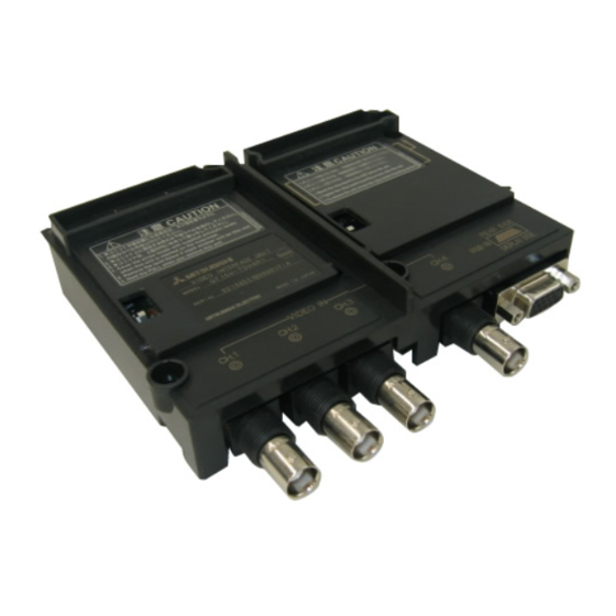
MODEL GT15V-75V4R1 Video/RGB Input Unit
MODEL GT15V-75V4 Video Input Unit
MODEL GT15V-75R1 RGB Input Unit
Thank you for choosing Mitsubishi Electric Graphic Operation Termi-
nal (GOT).
Prior to use, please read both this manual and detailed manual
thoroughly to fully understand the product.
User's Manual
MODEL
GT15V-75V4R1-U
MODEL
CODE
IB(NA)-0800348-G(1706)MEE
1D7M54
Advertisement
Table of Contents

Related Manuals for Mitsubishi Electric GT15V-75V4R1


Summary of Contents for Mitsubishi Electric GT15V-75V4R1
- Page 1 MODEL GT15V-75V4 Video Input Unit MODEL GT15V-75R1 RGB Input Unit User's Manual Thank you for choosing Mitsubishi Electric Graphic Operation Termi- nal (GOT). Prior to use, please read both this manual and detailed manual thoroughly to fully understand the product.
- Page 2 SAFETY PRECAUTIONS (Always read these precautions before using this equipment.) Before using this product, please read this manual and the relevant manuals introduced in this manual carefully and pay full attention to safety to handle the product correctly. The precautions given in this manual are concerned with this product. In this manual, the safety precautions are ranked as "WARNING"...
- Page 3 [DESIGN PRECAUTIONS] CAUTION Do not bunch the control wires or communication cables with the main circuit or power wires, or lay them close to each other. As a guide, separate the lines by a distance of at least 100mm (3.94 inches) otherwise malfunctions may occur due to noise.
- Page 4 [WIRING PRECAUTIONS] WARNING Be sure to shut off all phases of the external power supply used by the system before wiring. Failure to do so may result in an electric shock, product damage or malfunctions. CAUTION Exercise care to avoid foreign matter such as chips and wire offcuts entering the GOT.
- Page 5 [STARTUP/MAINTENANCE PRECAUTIONS] WARNING When power is on, do not touch the terminals. Doing so can cause an electric shock or malfunction. Before starting cleaning, always shut off GOT power externally in all phases. Not doing so can cause a unit failure or malfunction. Undertightening can cause a short circuit or malfunction.
- Page 6 Cover This manual confers no industrial property rights or any rights of any other kind, nor does it confer any patent licenses. Mitsubishi Electric Corporation cannot be held responsible for any problems involving industrial property rights which may occur as a result of using the contents noted in this manual.
-
Page 7: Table Of Contents
CONTENTS 1. OVERVIEW ....................1 2. SPECIFICATIONS ..................4 2.1 Video input unit specifications ..............4 2.2 RGB input unit specifications ..............5 2.3 Video/RGB input unit specifications ............6 2.4 Cable specifications ................. 7 2.4.1 Specifications of the cables (coaxial cables) used when displaying video images .............. - Page 8 GT15V-75R1 Mounting screw set (2 screws,2 stickers) Extend interface relay board Video/RGB input unit GT15V-75V4R1 Mounting screw set (2 screws,2 stickers) Extend interface relay board Compliance with the EMC and Low Voltage Directives To configure a system meeting the requirements of the EMC and Low Voltage Directives when incorporating the Mitsubishi GOT (EMC and Low Voltage Directives compliant) into other machinery or equipment, refer to "EMC AND LOW VOLTAGE DIRECTIVES"...
-
Page 9: Overview
Input Unit) • MODEL GT15V-75R1 RGB Input Unit (hereinafter referred to as the RGB Input Unit) • MODEL GT15V-75V4R1 Video/RGB Input Unit (hereinafter referred to as the Video/RGB Input Module). When mounting the above units with the GT1585V-STBA, GT1575V-STBA (hereinafter referred to as GOT), the images taken by video cameras or screens on personal computers can be displayed on the GOT. - Page 10 For the video/RGB input unit, functions of both video input unit (GT15V-75V4) and RGB input unit (GT15V-75R1) are available. Video camera GT15V-75V4R1 A 1254 CAUTION Do n ot mou nt not desmou nt a mo dule w hile th e powe r is supp lied.
- Page 11 *1: When connecting the unit to a personal computer, ground wire of the computer should be grounded. *2: Power on the video camera simultaneously with the GOT. *3: Video images and personal computer screens cannot be displayed on the GOT at the same time. To use the Video input unit, RGB input unit and Video/RGB input unit, make the Communication Settings.
-
Page 12: Specifications
2. SPECIFICATIONS 2.1 Video input unit specifications Item Specifications Color NTSC format, PAL format (interlaced format) Video input system Monochrome EIA format, CCIR format (interlaced format) Number of video input 4 channel channels Video Input signal IVp-p, 75 , composite signal input section 640x480 (possible to reduce to 320x240, 160x120) -
Page 13: Rgb Input Unit Specifications
2.2 RGB input unit specifications Item Specifications RGB input method (dot's) Analog RGB(SVGA; 800x600, VGA; 640x480) Number of video input 1 channel channels Input image signal 1Vp-p, 75 Synchronizing signal TTL, 1k input section 800 600 (refresh rate 60, 72, 75 [Hz]) Display size [dot's] 640 480 (refresh rate 60, 72, 75, 85 [Hz]) RGB external connection... -
Page 14: Video/Rgb Input Unit Specifications
2.3 Video/RGB input unit specifications Item Specifications Color NTSC format, PAL format (interlaced format) Video input system Monochrome EIA format, CCIR format (interlaced format) Number of video input 4 channel channels Video input Input signal IVp-p, 75 , composite signal section 640x480 (possible to reduce to 320x240, 160x120) Display size [dot's]... -
Page 15: Cable Specifications
2.4 Cable specifications The following shows the cable specifications, connection diagram, and connector used for the video input unit, RGB input unit, and video/RGB input unit. 2.4.1 Specifications of the cables (coaxial cables) used when displaying video images (1) Coaxial cable Use high frequency coaxial cable "3C-2V"... - Page 16 (a) Construction of BNC connector and coaxial cable. Parts of the BNC connector Construction of coaxial cable Outer sheath Outer conductor Washer Gasket Insulating material Internal conductive material Plug shell Clamp Contact (b) Connecting the BNC connector with the coaxial cable. 1) Remove the outer sheath of the coaxial cable in the specified 15mm...
- Page 17 *1: Soldered part must not have excess solder mound. *2: The tail end of the contact must come into close contact with the cut end of the insulating material. The contact must not be cutting in the insulating material. *3: Apply solder quickly so that the insulating material will not be deformed by heat.
-
Page 18: Specifications Of The Cables (9-Core Combined Cables) Used When Displaying Rgb Screens
2.4.2 Specifications of the cables (9-core combined cables) used when displaying RGB screens (1) Cable specifications Item Specifications Applicable cable Equivalent to SP23-23352A UL20276-SB Applicable wire size 9-core combined cable (recommended) (2) Connection diagram Coaxical Personal computer side GOT side RGND RGND GGND... -
Page 19: Part Names And External Dimensions
3. PART NAMES AND EXTERNAL DIMENSIONS 3.1 Part names and external dimensions of the video input unit GOT main unit 133 (5.24) (0.12) (0.10) 17.5 (0.69) (0.71) (0.71) (1.34) Unit : mm(inch) Dimensions of X when the video input unit is mounted to the GOT. -
Page 20: Part Names And External Dimensions Of The Rgb Input Unit
3.2 Part names and external dimensions of the RGB input unit GOT main unit 133 (5.24) (0.12) (0.10) 113.5 (4.47) Unit : mm(inch) Dimensions of X when the RGB input unit is mounted to the GOT. 12.1” 18 (0.71) 10.4” 21 (0.83) Unit: mm (inch) Name... -
Page 21: Part Names And External Dimensions Of The Video/Rgb Input Unit
3.3 Part names and external dimensions of the video/RGB input unit GOT main unit 133 (5.24) (0.12) (0.10) 17.5 26.0 (0.69) (0.71) (0.71) (1.34) (1.02) Unit : mm(inch) Dimensions of X when the video/RGB input unit is mounted to the GOT. 12.1”... -
Page 22: External Dimensions Of The Extension Interface Relay Board
3.4 External dimensions of the extension interface relay board 64 (2.52) Unit: mm (inch) -
Page 23: Installation Procedure
4. INSTALLATION PROCEDURE The installation procedure for the video/RGB input unit is explained using the GT1575. (1) Power off the GOT. (2) Remove two extension unit covers of the GOT. (3) Attach the extend interface relay board to the extend I/F-2 side on the GOT. - Page 24 (6) Fasten the bus connection unit by tightening the board fixing screws (2 places) with the tightening torque of 0.36 to 0.48 N•m. (7) When installing an extension unit on the unit that has been installed, remove the connector cover and the sticker. When not installing an extension unit on the unit that has been installed, in order to avoid receiving electrostatic, stick accessory stickers to cover the top of mounting screws (4 places).
- Page 25 MEMO...
- Page 26 Tel: +420-251-551-470 Tel: +84-8-3910-5945 Turkey Mitsubishi Electric Turkey A.S. Umraniye India Mitsubishi Electric India Pvt. Ltd. Pune Branch Branch Emerald House, EL -3, J Block, M.I.D.C., Serifali Mahallesi Nutuk Sokak No:5, TR-34775 Bhosari, Pune - 411026, Maharashtra, India Umraniye / Istanbul, Turkey...