Table of Contents
Advertisement
Quick Links
Download this manual
See also:
Manual
Advertisement
Table of Contents

Related Manuals for Siemens siprotec 7SD610


Summary of Contents for Siemens siprotec 7SD610
- Page 1 Preface Introduction Functions SIPROTEC Mounting and Commissioning Differential Protection Technical Data 7SD610 Appendix V4.6 Literature Manual Glossary Index C53000-G1176-C145-4...
- Page 2 We reserve the right to make technical improvements without SIPROTEC, SINAUT, SICAM and DIGSI are registered trade- notice. marks of Siemens AG. Other designations in this manual might be trademarks whose use by third parties for their own purposes would infringe the rights of the owner.
-
Page 3: Mounting And Commissioning 3
(Low-voltage directive 73/23 EEC). This conformity is proved by tests conducted by Siemens AG in accordance with Article 10 of the Council Directive in agreement with the generic standards EN 61000-6-2 and EN 61000-6-4 for the EMC directive, and with the standard EN 61000-6-2 and EN 61000-6-4 for the low-voltage directive. - Page 4 Should further information on the SIPROTEC 4 System be desired or should particular problems arise which are not covered sufficiently for the purchaser's purpose, the matter should be referred to the local Siemens representative. Training Courses Individual course offerings may be found in our Training Catalogue, or questions may be directed to our training centre in Nuremberg.
- Page 5 Preface Definition QUALIFIED PERSONNEL For the purpose of this instruction manual and product labels, a qualified person is one who is familiar with the installation, construction and operation of the equipment and the hazards involved. In addition, he has the following qualifications: •...
- Page 6 Preface External binary output signal with number (device indication) used as input signal Example of a parameter switch designated FUNCTION with the address 1234 and the possible settings ON and OFF Besides these, graphical symbols are used according to IEC 60617-12 and IEC 60617-13 or symbols derived from these standards.
-
Page 7: Table Of Contents
Contents Introduction..............15 Overall Operation . - Page 8 Contents Differential Protection ........... . . 62 2.3.1 Function Description .
- Page 9 Contents 2.11 Undervoltage and Overvoltage Protection (optional)......151 2.11.1 Overvoltage protection ........... 151 2.11.2 Undervoltage protection .
- Page 10 Contents 2.16 Function Control and Circuit Breaker Test ........220 2.16.1 Function Control .
- Page 11 Contents 2.18 Command Processing ........... 256 2.18.1 Control Authorization .
- Page 12 Contents Technical Data ..............319 General .
- Page 13 Contents Terminal Assignments ........... . 372 A.2.1 Housing for Panel Flush and Cubicle Mounting .
- Page 14 Contents 7SD610 Manual C53000-G1176-C145-4...
-
Page 15: Introduction
Introduction The SIPROTEC 4 7SD610 is introduced in this chapter. The device is presented in its application, characteristics, and functional scope. Overall Operation Application Scope Characteristics 7SD610 Manual C53000-G1176-C145-4... -
Page 16: Overall Operation
1 Introduction Overall Operation The SIPROTEC 4 7SD610 line protection is equipped with a powerful microprocessor system. This provides fully numerical processing of all functions in the device, from the acquisition of the measured values up to the output of commands to the circuit break- ers, as well as the exchange of measured data with the other ends of the protected area. - Page 17 1.1 Overall Operation A voltage measuring input is provided for each phase-earth voltage. In principle, the differential protection does not require any measured voltage, however, for the direct- ed overcurrent time protection the connection of the phase earth voltages U is definitely required.
- Page 18 1 Introduction Serial Interfaces Via the serial operator interface in the front panel the communication with a personal computer using the operating program DIGSI is possible. This facilitates a comfortable handling of all device functions. The service interface can also be used for communication with a personal computer using DIGSI.
-
Page 19: Application Scope
1.2 Application Scope Application Scope The numerical Differential Protection SIPROTEC 4 7SD610 is a selective short-circuit protection for overhead lines and cables with single- and multi-ended infeeds in radial, ring or any type of meshed systems of any transmission level. Conditioning of the system starpoint is irrelevant, as measuring data are compared separately for each phase. - Page 20 1 Introduction pole, three-pole or single- and three-pole automatic reclosure as well as multi-shot au- tomatic reclosure. Apart from the short-circuit protection functions mentioned, a thermal overload protec- tion has been integrated which protects in particular cables and power transformers from undue heating through overload.
- Page 21 1.2 Application Scope personal computer and the DIGSI operating software, e.g. to operate several devices via a central PC. The system interface is used for central communication between the device and a control centre. It can be operated through the RS232, RS485 or FO port. For data transmission there are several standardized protocols available.
-
Page 22: Characteristics
1 Introduction Characteristics General Features • Powerful 32-bit microprocessor system • Complete digital processing of measured values and control, from the sampling of the analog input values, the processing and organization of the communication between devices up to the closing and tripping commands to the circuit breakers •... - Page 23 1.3 Characteristics Restricted Earth • Earth fault protection for earthed transformer windings Fault Protection • Short tripping time • High sensitivity for earth faults • High stability against external earth faults using the magnitude and phase relation- ship of through-flowing earth current External Direct and •...
- Page 24 1 Introduction Voltage Protection • Overvoltage and undervoltage detection with different stages (optional) • Two overvoltage stages for the phase-earth voltages • Two overvoltage stages for the phase-phase voltages • Two overvoltage stages for the positive sequence voltage, optionally with com- pounding •...
- Page 25 1.3 Characteristics Commissioning; • Display of magnitude and phase angle of local and remote measured values Operation; • Indication of the calculated differential and restraint currents Maintenance • Display of measured values of the communication link, such as transmission delay and availability Command •...
- Page 26 1 Introduction • Commissioning aids such as connection and direction checks as well as circuit breaker test functions • The WEB-Monitor (installed on a PC or a laptop) widely supports the testing and commissioning procedure. The communication topology of the differential protec- tion and communication system, phasor diagrams of all currents and (if applicable) voltages at both ends of the differential system are displayed as a graph ■...
-
Page 27: Functions
Functions This chapter describes the individual functions of the SIPROTEC 4 device 7SD610. It shows the setting possibilities for each function in maximum configuration. Guidelines for establishing setting values and, where required, formulae are given. Additionally, on the basis of the following information, it may be defined which func- tions are to be used. -
Page 28: General
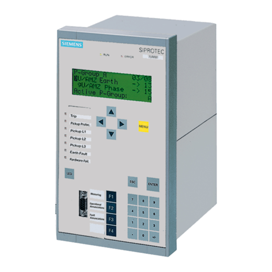
2 Functions General A few seconds after the device is switched on, the default display appears on the LCD. In the 7SD610 the measured values are displayed. Configuration settings can be entered by using a PC and the DIGSI operating software and transferred via the operator interface on the front panel of the device or via the service interface. -
Page 29: Setting Notes
2.1 General The available protection and supplementary functions can be configured as Enabled or Disabled. For some functions, a choice may be presented between several options which are explained below. Functions configured as Disabled are not processed by the 7SD610. There are no indications, and corresponding settings (functions, limit values) are not displayed during setting. - Page 30 2 Functions overcurrent stages are identical. The characteristics are shown in the Technical Data (Section 4.6). You can also disable the time overcurrent protection (Disabled). If the device features an automatic reclosing function, address 133 and 134 are of im- portance.
-
Page 31: Settings
2.1 General to Enabl. w. comp. (available with compounding). Do not use compounding in lines with series capacitors! For the trip circuit supervision set at address 140 Trip Cir. Sup. the number of trip circuits to be monitored: 1 trip circuit, 2 trip circuits or 3 trip circuits, unless you omit it (Disabled). -
Page 32: General Power System Data (Power System Data 1)
2 Functions Addr. Parameter Setting Options Default Setting Comments Trip Cir. Sup. Disabled Disabled Trip Circuit Supervision 1 trip circuit 2 trip circuits 3 trip circuits REF PROT. Disabled Disabled Restricted earth fault protection Enabled Therm.Overload Disabled Disabled Thermal Overload Protection Enabled TRANSFORMER Transformer inside protection... - Page 33 2.1 General Nominal Values of In principle, the differential protection does not require any measured voltage. Howev- Transformers er, voltages can be connected. These voltages allow to display and log voltages, and to calculate various components of power. If necessary, they can also serve for deter- mining the life line condition in case of automatic reclosure.
- Page 34 2 Functions Connection of the The device features four current measurement inputs, three of which are connected Currents to the set of current transformers. Various possibilities exist for the fourth current input • Connection of the I input to the earth current in the starpoint of the set of current transformers on the protected feeder (normal connection): Address 220 is then set to: I4 transformer = In prot.
- Page 35 2.1 General In address 240 the minimum trip command duration TMin TRIP CMD is set. It applies Trip command duration to all protective and control functions which may issue a trip command. It also deter- mines the duration of the trip pulse when a circuit breaker test is initiated via the device.
- Page 36 2 Functions Usually, the internal burden of the current transformers is stated in the test report. If it is unknown, it can be roughly calculated from the DC resistance R of the secondary winding. ≈ R · I The ratio between operational accuracy limit factor and rated accuracy limit factor n'/n is set at address 251 K_ALF/K_ALF_N.
- Page 37 2.1 General The resistance of the secondary lines is (with the resistivity for copper ρ = 0.0175 Ωmm Here, the most unfavourable case is assumed, i.e. the current (as it is the case with single-phase faults) flows back and forth via the secondary lines (factor 2). From that the power for nominal current I = 5 A is calculated = 0.175 Ω...
-
Page 38: Settings
2 Functions This results in the following: Rated current at rated voltage = 184 A Rated current at U + 10 % = 167 A Rated current at U – 10 % = 202 A The maximum deviation from this current is This maximum deviation δ... -
Page 39: Change Group
2.1 General Addr. Parameter Setting Options Default Setting Comments Distance Unit Distance measurement unit Miles 240A TMin TRIP CMD 0.02 .. 30.00 sec 0.10 sec Minimum TRIP Command Dura- tion 241A TMax CLOSE CMD 0.01 .. 30.00 sec 1.00 sec Maximum Close Command Dura- tion T-CBtest-dead... -
Page 40: Settings
2 Functions 2.1.3.3 Settings Addr. Parameter Setting Options Default Setting Comments ACTIVE GROUP Group A Group A Active Setting Group is Group B Group C Group D CHANGE Group A Group A Change to Another Setting Group Group B Group C Group D Binary Input Protocol... - Page 41 2.1 General current transformers have different rated currents at the ends of the protected object, set the highest rated current value for all ends. This setting will not only have an impact on the displays of the operational measured values in per cent, but it must also be exactly the same for each end of the pro- tected object since it is the basis for the current comparison at the ends.
- Page 42 2 Functions Calculation example: Transformer YNd5 35 MVA 110 kV / 25 kV Y-winding with tap changer ±10 % For the regulated winding (110 kV) this results in: Maximum voltage = 121 kV Minimum voltage = 99 kV Voltage to be set (address 1103) The OPERATION POWER (address 1106) is the direct primary rated apparent power for transformers and other machines.
- Page 43 2.1 General advantage. Set the correct vector group of the transformer according to the above- mentioned considerations. Address 1162 VECTOR GROUP I is therefore relevant for the differential protection whereas address 1161 VECTOR GROUP U serves as a basis for the calculation of the measured voltages beyond the transformer.
- Page 44 2 Functions stance, during the test of the protection equipment, when the system-side load current cannot be cut off and the test current is injected in parallel to the load current. While the time SI Time all Cl. (address 1132, see above) is activated following each recognition of line energization, SI Time Man.Cl (address 1150) is the time following manual closure during which special influence of the protection functions is activated (e.g.
- Page 45 2.1 General Three-pole Three-pole coupling is only relevant if single-pole auto-reclosures are carried out. If Coupling not, tripping is always three-pole. The rest of this margin heading is then irrelevant. Address 1155 3pole coupling determines whether any multi-phase pickup leads to a three-pole tripping command, or whether only multi-pole tripping decisions result in a three-pole tripping command.
-
Page 46: Settings
2 Functions Figure 2-3 Multiple fault on a double-circuit line next to a generator Address 1156 Trip2phFlt determines that the short-circuit protective functions perform only a single-pole trip in case of isolated two-phase faults (clear of ground), provided that single-pole tripping is possible and permitted. This allows a single-pole reclose cycle for this kind of fault. -
Page 47: Information List
2.1 General Addr. Parameter Setting Options Default Setting Comments 1130A PoleOpenCurrent 0.05 .. 1.00 A 0.10 A Pole Open Current Threshold 0.25 .. 5.00 A 0.50 A 1131A PoleOpenVoltage 2 .. 70 V 30 V Pole Open Voltage Threshold 1132A SI Time all Cl. - Page 48 2 Functions Information Type of In- Comments formation >FAIL:Feeder VT >Failure: Feeder VT (MCB tripped) >CB1 Pole L1 >CB1 Pole L1 (for AR,CB-Test) >CB1 Pole L2 >CB1 Pole L2 (for AR,CB-Test) >CB1 Pole L3 >CB1 Pole L3 (for AR,CB-Test) >CB1 Ready >CB1 READY (for AR,CB-Test) >CB faulty >CB faulty...
-
Page 49: Protection Data Interfaces And Protection Data Topology
2.2 Protection Data Interfaces and Protection Data Topology Protection Data Interfaces and Protection Data Topology Devices protecting an object protected by current transformer sets, must exchange data of the protected object. This applies not only to the measured quantities relevant to the actual differential pro- tection, but also to all data which are to be available at the ends. - Page 50 2 Functions Table 2-2 Communication via Direct Connection Module in Connector Fibre Type Optical Perm. Path At- Distance, the Device Type Wavelength tenuation Typical Multimode 820 nm 8 dB 1.5 km (0.94 62.5/125 µm miles) Multimode 820 nm 16 dB 3.5 km (2.18 62.5/125 µm miles)
-
Page 51: Operating Modes Of The Differential Protection
2.2 Protection Data Interfaces and Protection Data Topology You can define a limit for the permissible rate of faulty data telegrams. When, during operation, this limit is exceeded, an alarm is given (e.g. „PI1 Error“, No. 3258). You may use this alarm to block the differential protection, either via binary output and input, or via logical combination by means of the integrated user-definable logic (CFC). - Page 52 2 Functions protection. The set thresholds for the differential current now only evaluate the local current. A device can be logged out and on as described below: • Using the integrated keypad: Menu Control/Taggings/Set: „Logout“ • Via DIGSI: Control / Taggings „Logout local device“ •...
-
Page 53: Differential Protection Test Mode
2.2 Protection Data Interfaces and Protection Data Topology If all requirements are met, the request is accepted and the indication „Logout“ OFF (No. 3484) is generated. According to the request source, either the indication „Logout ON/off“ OFF (No. 3459) or „Logout ON/offBI“ OFF (No. 3460) is output. - Page 54 2 Functions Figure 2-8 Logic diagram of the test mode Depending on the way used for controlling the test mode, either the indication „Test Diff.ONoff“ (No. 3199) or „TestDiffONoffBI“ (No. 3200) is generated. The way used for deactivating the test mode always has to be identical to the way used for activating.
-
Page 55: Differential Protection Commissioning Mode
2.2 Protection Data Interfaces and Protection Data Topology If a test switch is to be used for changing to test mode, we recommed the following procedure: • Block the differential protection via a binary input. • Use the test switch to activate/deactivate the test mode. •... -
Page 56: Protection Data Interfaces
2 Functions The following figures show possible variants for controlling the binary inputs. If a switch is used for the control (Figure 2-13), it has to be observed that binary input „>Comm. Diff ON“ (No. 3260) has to be parameterised as NO contact and that binary input „>Comm. - Page 57 2.2 Protection Data Interfaces and Protection Data Topology F.optic direct, i.e. communication directly by fibre-optic cable with 512 kbit/s; Com conv 64 kB , i.e. via communication converters with 64 kbit/s (G703.1 or X.21); Com conv 128 kB, i.e. via communication converters with 128 kbit/s (X.21, copper cable);...
-
Page 58: Settings
2 Functions At address 4513 you set a limit value PROT1 max ERROR for the permissible rate of faulty protection data telegrams. This parameter can only be altered in DIGSI at Ad- ditional Settings. The preset value 1 % means that one faulty telegram per 100 tele- grams is permissible. -
Page 59: Information List
2.2 Protection Data Interfaces and Protection Data Topology Addr. Parameter Setting Options Default Setting Comments 4801 GPS-SYNC. GPS synchronization 4803A TD GPS FAILD 0.5 .. 60.0 sec 2.1 sec Delay time for local GPS-pulse loss 2.2.3.3 Information List Information Type of In- Comments formation 3215... - Page 60 2 Functions exchange of information between several differential protection systems (thus also for several protected objects) can be executed via the same communication system. If you work with different physical interfaces and communications links, please make sure that every protection data interface corresponds to the projected communication link.
-
Page 61: Settings
2.2 Protection Data Interfaces and Protection Data Topology 2.2.4.2 Settings Addr. Parameter Setting Options Default Setting Comments 4701 ID OF RELAY 1 1 .. 65534 Identification number of relay 1 4702 ID OF RELAY 2 1 .. 65534 Identification number of relay 2 4710 LOCAL RELAY relay 1... -
Page 62: Differential Protection
2 Functions Differential Protection The differential protection is the main function of the device. It is based on current comparison. For this, one device must be installed at each end of the zone to be pro- tected. The devices exchange their measured quantities via communications links and compare the received currents with their own. - Page 63 2.3 Differential Protection Figure 2-16 shows this for a line with two ends. Each device measures the local current and sends the information on its intensity and phase relation to the opposite end. The interface for this communication between protection devices is called protec- tion data interface.
- Page 64 2 Functions The secondary currents which are applied to the devices via the current transformers, are subject to measuring errors caused by the response characteristic of the current transformers and the input circuits of the devices. Transmission errors such as signal jitters can also cause deviations of the measured quantities.
- Page 65 2.3 Differential Protection If an influencing parameter cannot be determined — e.g. the frequency if no sufficient measured quantities are available — the device will assume nominal values by defini- tion. In this example, frequency means that if the frequency cannot be determined because no sufficient measured quantities are available, the device will assume nominal frequency.
- Page 66 2 Functions Figure 2-18 Logic diagram of the inrush restraint for one phase Since the inrush restraint operates individually for each phase, the protection is fully operative when the transformer is switched onto a single-phase fault, whereby an inrush current may possibly flow through one of the undisturbed phases. It is, however, also possible to set the protection in such a way that when the permissible harmonic content in the current of only one single phase is exceeded, not only the phase with the inrush current but also the remaining phases of the differential stage are blocked.
- Page 67 2.3 Differential Protection The restraining current counteracts the differential current. It is the total of the maximum measured errors at the ends of the protected object and is calculated from the current measured quantities and power system parameters that were set. There- fore the highest possible error value of the current transformers within the nominal range and/or the short-circuit current range is multiplied with the current flowing through each end of the protected object.
- Page 68 2 Functions The charge comparison protection function does not sum up the complex current phasors at the ends of the protected object, but the integral of currents calculated ac- cording to the following formula: It includes the integration interval of t to t , which is selected in the 7SD610 device to period...
- Page 69 2.3 Differential Protection Pickup of the differ- Figure 2-21 illustrates the logic diagram of the breaker failure protection. The phase- ential protection selective indications of the stages are summarised to form general phase indications. Additionally the device provides information of which stage picked up. Figure 2-21 Pickup logic for the differential protection function As soon as the differential protection function registers a fault within its tripping zone,...
-
Page 70: Setting Notes
2 Functions is issued. For the differential protection function itself, this pickup signal is of no concern since the tripping conditions are available at the same time. This signal, how- ever, is necessary for the initiation of internal or external supplementary functions (e.g. fault recording, automatic reclosure). - Page 71 2.3 Differential Protection The current sensitivity is set with address 1210 I-DIFF>. It is determined by the Pickup Value of the Differential Current entire current flowing into a protected zone in case of a fault. This is the total fault current regardless of how it is distributed between the ends of the protected object.
- Page 72 2 Functions 2.1.2.1 Setting information, Margin heading „Power Transformer with Voltage Regula- tion“. Pickup value When switching on long, unloaded cables, overhead lines and arc-compensated lines, during switch-on pronounced higher-frequency transient reactions may take place. These peaks are considerably damped by means of a digital filter in the differential protection. A pickup value I-DIF>SWITCH ON (address 1213) can be set to reliably prevent single-sided pickup of the protection.
-
Page 73: Settings
2.3 Differential Protection The pickup thresholds are finally checked during commissioning. Further information can be found in chapter Installation and Commissioning. Pickup value when If bushing transformers are used for a transformer in the protected line section, stray switching on the fluxes through the bushing transformers may occur when reclosing after an external charge comparison fault. -
Page 74: Information List
2 Functions Addr. Parameter Setting Options Default Setting Comments 0.00 .. 0.50 sec; ∞ 1218 T3I0 1PHAS 0.04 sec Delay 1ph-faults (comp/isol. star-point) 1219A I> RELEASE DIFF 0.10 .. 20.00 A; 0 0.00 A Min. local current to release DIFF-Trip 0.50 .. - Page 75 2.3 Differential Protection Information Type of In- Comments formation 3177 Diff Flt. L1E Diff: Fault detection L1E 3178 Diff Flt. 1p.L2 Diff: Fault detection L2 (only) 3179 Diff Flt. L2E Diff: Fault detection L2E 3180 Diff Flt. L12 Diff: Fault detection L12 3181 Diff Flt.
-
Page 76: Breaker Intertrip And Remote Tripping
2 Functions Breaker Intertrip and Remote Tripping 7SD610 allows to transmit a tripping command created by the local differential protec- tion to the other end of the protected object (intertripping). Likewise, any desired command of another internal protection function or of an external protection, monitor- ing or control equipment can be transmitted for remote tripping. -
Page 77: Setting Notes
2.4 Breaker Intertrip and Remote Tripping Receiving circuit On the receiving end the signal can lead to a trip. Alternatively it can also cause an alarm only. Figure 2-24 shows the logic diagram. If the received signal is to cause the trip, it will be forwarded to the tripping logic. -
Page 78: Settings
2 Functions Intertrip/Remote If the intertrip function is activated, it will automatically start when the differential tripping protection trips. If the relevant binary inputs are allocated and activated by an external source, the in- tertrip signal is transmitted as well. In this case, the signal to be transmitted can be delayed with address 1303 T-ITRIP BI. - Page 79 2.4 Breaker Intertrip and Remote Tripping Information Type of In- Comments formation 3519 ITrp.TRIP 1p L2 I.Trip: TRIP - Only L2 3520 ITrp.TRIP 1p L3 I.Trip: TRIP - Only L3 3521 ITrp.TRIP L123 I.Trip: TRIP L123 3522 Diff TRIP 1pole I.Trip: TRIP 1pole 3523 Diff TRIP 3pole...
-
Page 80: Restricted Earth Fault Protection (Optional)
2 Functions Restricted Earth Fault Protection (optional) The restricted earth fault protection detects earth faults in power transformers, the starpoint of which is led to earth. It is also suitable when a starpoint former is installed within a protected zone of a non-earthed power transformer. A precondition is that a current transformer is installed in the starpoint connection, i.e. -
Page 81: Functional Description
2.5 Restricted Earth Fault Protection (optional) 2.5.2 Functional Description Measuring During healthy operation, no starpoint current ISP flows through the starpoint lead. principle The sum of the phase currents 3I is also approximately zero. When an earth fault occurs in the protected zone, a starpoint current I will flow;... - Page 82 2 Functions ' = I " = I Only 3I ' acts as the tripping effect quantity. During a fault within the protected zone this current is always present. Figure 2-29 Principle of restricted earth fault protection When an earth fault occurs outside the protected zone, another earth current flows though the phase current transformers.
- Page 83 2.5 Restricted Earth Fault Protection (optional) 1. Through-fault current on an external earth fault: " is in phase opposition with 3I ', and of equal magnitude, i.e. 3I " = –3I = |3I = |3I ' + 3I '| – |3I ' –...
- Page 84 2 Functions Figure 2-30 Tripping characteristic of the restricted earth fault protection depending on the earth current ratio 3I ”/3I ' (both currents in phase + or counter-phase –); > = setting; I = tripping current Trip It was assumed in the above examples that the currents 3I "...
- Page 85 2.5 Restricted Earth Fault Protection (optional) This limit angle determines for which phase displacement between 3I " and 3I ' the ' grows to ∞, i.e. no pickup occurs. In 7SD610 k = 4. pickup value for 3I " = 3I The restraint quantity I in the above example a) is quadrupled once more;...
-
Page 86: Setting Notes
2 Functions Figure 2-33 Increasing the pickup value Figure 2-34 Logic diagram of the restricted earth fault protection (simplified) 2.5.3 Setting Notes General The restricted earth fault protection can only operate if this function has been set during configuration of the functional scope (Section 2.1.2) under address 141 REF PROT. -
Page 87: Settings
2.5 Restricted Earth Fault Protection (optional) Note When delivered from factory, the restricted earth fault protection is switched OFF. The reason is that the protection must not be in operation unless at least the assigned side and CT polarity have been properly set before. Without proper settings, the device may show unexpected reactions (incl. -
Page 88: Information List
2 Functions Addr. Parameter Setting Options Default Setting Comments 0.00 .. 60.00 sec; ∞ 4112A T I-REF> 0.00 sec T I-REF> Time Delay 4113A SLOPE 0.00 .. 0.95 0.00 Slope of Charac. I-REF> = f(I-SUM) 2.5.5 Information List Information Type of In- Comments formation 5803... -
Page 89: Direct Local Trip
2.6 Direct Local Trip Direct Local Trip Any signal from an external protection or monitoring device can be coupled into the signal processing of the 7SD610 by means of a binary input. This signal can be de- layed, alarmed and routed to one or several output relays. 2.6.1 Method of Operation External trip of the... -
Page 90: Settings
2 Functions 2.6.3 Settings Addr. Parameter Setting Options Default Setting Comments 2201 FCT Direct Trip Direct Transfer Trip (DTT) 0.00 .. 30.00 sec; ∞ 2202 Trip Time DELAY 0.01 sec Trip Time Delay 2.6.4 Information List Information Type of In- Comments formation 4403... -
Page 91: Direct Remote Trip And Transmission Of Binary Information
2.7 Direct Remote Trip and Transmission of Binary Information Direct Remote Trip and Transmission of Binary Information 2.7.1 Function Description 7SD610 allows the transmission of up to 4 items of binary information of any type from one device to the other via the communication link provided for protection tasks. These are transmitted like protection signals with high priority, i.e. -
Page 92: Information List
2 Functions 2.7.2 Information List Information Type of In- Comments formation 3541 >Remote Trip1 >Remote Trip 1 signal input 3542 >Remote Trip2 >Remote Trip 2 signal input 3543 >Remote Trip3 >Remote Trip 3 signal input 3544 >Remote Trip4 >Remote Trip 4 signal input 3545 RemoteTrip1 rec Remote Trip 1 received... -
Page 93: Instantaneous High-Current Switch-Onto-Fault Protection (Sotf)
2.8 Instantaneous High-Current Switch-onto-Fault Protection (SOTF) Instantaneous High-Current Switch-onto-Fault Protection (SOTF) 2.8.1 Function Description General The instantaneous high-current switch-onto-fault protection function is provided to dis- connect immediately, and without delay, feeders that are switched onto a high-current fault. It serves, e.g. as a rapid protection for connecting a feeder with closed grounding disconnector. -
Page 94: Setting Notes
2 Functions Figure 2-36 Logic diagram of the high current switch on to fault protection 2.8.2 Setting Notes General A prerequisite for the application of the direct and remote tripping functions is that during the configuration of the scope of functions (Section 2.1.1) in address 124HS/SOTF-O/C = Enabled was applied. -
Page 95: Settings
2.8 Instantaneous High-Current Switch-onto-Fault Protection (SOTF) long lines with small source impedance. In other cases it is set to ∞ (default setting). This parameter can only be altered with DIGSI under Additional Settings. When using a PC and DIGSI for the parameterisation, the values can be optionally entered as primary or secondary quantities. -
Page 96: Information List
2 Functions Addr. Parameter Setting Options Default Setting Comments 2401 FCT HS/SOTF-O/C Inst. High Speed/SOTF- O/C is 0.10 .. 15.00 A; ∞ 2404 I>>> 1.50 A I>>> Pickup 0.50 .. 75.00 A; ∞ 7.50 A 1.00 .. 25.00 A; ∞ ∞... -
Page 97: Backup Time Overcurrent Protection
2.9 Backup Time Overcurrent Protection Backup Time Overcurrent Protection The 7SD610 features a time overcurrent protection function which can be used as either a back-up or an emergency overcurrent protection. All elements may be config- ured independently of each other and combined according to the user's requirements. 2.9.1 General Whereas the differential protection can only operate correctly if both devices receive... - Page 98 2 Functions three phase currents of three star-connected current transformers must be available and connected. For the directional Iph>stages, the used measuring voltage is determined by the fault condition. The selection occurs according to the availability of the measured values listed below.
- Page 99 2.9 Backup Time Overcurrent Protection Directional The directional characteristic of the directional overcurrent stages is preset. From the Characteristic voltage and current vectors used for direction determination the angle difference ϕ(U) - ϕ(I) is calculated via the impedance Z Z = U/I, and the direction determined using the displayed directional characteristic.
- Page 100 2 Functions Logic diagram of the I>> stage Figure 2-38 Output indications associated with the pickup signals are listed in Table 2-3 Output indications associated with the trip signals are listed in Table 2-4 The logic of the overcurrent stage I> is the same as that of the I>> stages. In all ref- Definite time over- erences Iph>>...
- Page 101 2.9 Backup Time Overcurrent Protection The I>>> stage can, however, also be used as a standard additional and independent overcurrent stage, since it works independent of the other stages. In this case, the enable input „>I-STUB ENABLE“ must be activated permanently (via a binary input or CFC).
- Page 102 2 Functions The pickup of the phase current stages is non-directional, if address 2680 Direction Iph> is parameterized to Non-Directional. The pickup of the earth stage is non-directional, if address 2683 Direction 3I0> is parameterized to Non- Directional. The setting values for the phase current is Iph> Dir., and 3I0> Dir. for the earth current.
- Page 103 2.9 Backup Time Overcurrent Protection Logic diagram of the I> stage Figure 2-40 Output indications associated with the pickup signals are listed in Table 2-3 Output indications associated with the trip signals are listed in Table 2-4 The indications „O/C L2 forward“, „O/C L3 forward“, „O/C L2 reverse“, „O/C L3 reverse“ have not been represented in the Figure, however, they are reported if necessary.
- Page 104 2 Functions Inverse time over- The logic of the inverse overcurrent stage also operates chiefly in the same way as current stage I the remaining stages. However, the time delay is calculated here based on the type of the set characteristic, the intensity of the current and a time multiplier (following fig- ure).
- Page 105 2.9 Backup Time Overcurrent Protection Logic diagram of the I Figure 2-41 stage (inverse time overcurrent protection) - example of IEC curve Output indications associated with the pickup signals are listed in Table 2-3 Output indications associated with the trip signals are listed in Table 2-4 Directional inverse The logic of the directional inverse overcurrent stage operates chiefly in the same way time overcurrent...
- Page 106 2 Functions may be selected, which is added to the inverse time. The possible characteristics are shown in the Technical Data. The individual phase or earth specific directional indications (7240 to 7247) are used to generate the indications „O/C Dir.forward“ or „O/C Dir.reverse“, if a valid direction result (forward or backward) was determined for a phase or earth current.
- Page 107 2.9 Backup Time Overcurrent Protection Logic diagram of the I Figure 2-42 stage (directional, inverse time overcurrent protection), for example IEC character- istics Output indications associated with the pickup signals are listed in Table 2-3 Output indications associated with the trip signals are listed in Table 2-4 The indications „O/C L2 forward“, „O/C L3 forward“, „O/C L2 reverse“, „O/C L3 reverse“...
- Page 108 2 Functions Instantaneous trip- If automatic reclosure must be performed, a quick clearance of the fault before reclo- ping before auto- sure is usually desirable. A release signal from an external automatic reclosure device can be injected via binary input „>O/C InstTRIP“. The interconnection of the inter- matic reclosure nal auto recloser is performed via an additional CFC logic, which typically connects the output signal 2889 „AR 1.CycZoneRel“...
- Page 109 2.9 Backup Time Overcurrent Protection Internal indication Display Output indication I>>> PU L1 2-39 I>>> PU L2 2-39 „I-STUB PICKUP“ 7201 I>>> PU L3 2-39 I>>> PU E 2-39 I> ger PU L1 2-40 I> ger PU L2 2-40 „O/C PICK. I>Dir“ 7202 I>...
- Page 110 2 Functions Table 2-4 Trip signals of the single phases Internal indication Display Output indication I>> TRIP L1 2-38 I> TRIP L1 I>>> TRIP L1 2-39 7212 or „O/C TRIP 1p.L1“ or „O/C TRIP L123“ I> ger TRIP L1 2-40 7215 Ip TRIP L1 2-41...
-
Page 111: Setting Notes
2.9 Backup Time Overcurrent Protection 2.9.3 Setting Notes During configuration of the scope of functions for the device (address 126) the avail- General able characteristics were determined. Depending on the configuration and the order variant, only those parameters that apply to the selected characteristics are accessible in the procedures described below. - Page 112 2 Functions If the I>> stages are used for instantaneous tripping before the automatic reclosure (via CFC interconnection), the current setting corresponds to the I> or I stages (see below). In this case only the different delay times are of interest. The times T Iph>>(address 2611) and T 3I0>>...
- Page 113 2.9 Backup Time Overcurrent Protection A similar calculation must be carried out for earth faults, with the maximum earth current occurring at the line end during a short-circuit being decisive. The set time delays are pure additional delays, which do not include the operating time (measuring time).
- Page 114 2 Functions The delay time T Iph> (address2621) orT Iph> Dir. (address2682) results from the grading coordination chart defined for the network. If implemented as emergency overcurrent protection, shorter tripping times are advisable (one grading time step above the fast tripping stage), as this function is only activated in the case of the loss of the local measured voltage.
- Page 115 2.9 Backup Time Overcurrent Protection Primary: Set value IP = 630 A, Secondary: Set value IP = 5.25 A, i.e. (630 A/600 A) X 5 A. The set time multiplicator T Ip Time Dial (address 2642) or T Ip Dir. (address 2690) results from the grading coordination chart defined for the network.
- Page 116 2 Functions Definite Inv.. The characteristics and equations they are based on are listed in the „Technical Data“. They apply for directional and non-directional stages alike. For the setting of the current thresholds Ip> (address 2640) or Ip> Dir. (address 2689) and 3I0p PICKUP (address 2650) or.
-
Page 117: Settings
2.9 Backup Time Overcurrent Protection The I-STUB stage can be used as an additional definite time overcurrent stage since Additional stage it operates independently of the other stages. In this case, the enable input „>I-STUB >>> ENABLE“ (No. 7131) must be activated permanently (via a binary input or CFC). Since the I-STUB stage has an additional enable input, it is also suitable e.g. - Page 118 2 Functions Addr. Parameter Setting Options Default Setting Comments 0.10 .. 25.00 A; ∞ 2610 Iph>> 2.00 A Iph>> Pickup 0.50 .. 125.00 A; ∞ 10.00 A 0.00 .. 30.00 sec; ∞ 2611 T Iph>> 0.30 sec T Iph>> Time delay 0.05 ..
- Page 119 2.9 Backup Time Overcurrent Protection Addr. Parameter Setting Options Default Setting Comments 2656 T 3I0p Add 0.00 .. 30.00 sec 0.00 sec T 3I0p Additional Time Delay 2660 IEC Curve Normal Inverse Normal Inverse IEC Curve Very Inverse Extremely Inv. LongTimeInverse 2661 ANSI Curve...
-
Page 120: Information List
2 Functions Addr. Parameter Setting Options Default Setting Comments 0.05 .. 4.00 A; ∞ ∞ A 2694 3I0p Dir. 3I0p directional Pickup 0.25 .. 20.00 A; ∞ ∞ A 0.05 .. 3.00 sec; ∞ 2695 T 3I0p Dir. 0.50 sec T 3I0p Dir.:Inv.-Time delay for IEC-Char 0.50 .. - Page 121 2.9 Backup Time Overcurrent Protection Information Type of In- Comments formation 7177 O/C Pickup L12E Backup O/C Pickup L12E 7178 O/C PU 1p. L3 Backup O/C Pickup - Only L3 7179 O/C Pickup L3E Backup O/C Pickup L3E 7180 O/C Pickup L31 Backup O/C Pickup L31 7181 O/C Pickup L31E...
-
Page 122: Automatic Reclosure Function (Optional)
2 Functions 2.10 Automatic Reclosure Function (optional) Experience shows that about 85% of the arc faults on overhead lines are extinguished automatically after being tripped by the protection. The line can therefore be re-ener- gised. Reclosure is performed by an automatic reclose function (AR). Automatic reclosure is only permitted on overhead lines because the option of auto- matic extinguishing of a fault arc only exists there. - Page 123 2.10 Automatic Reclosure Function (optional) Figure 2-43 Timing diagram of a double-shot reclosure with action time (2nd reclosure successful) The integrated automatic reclosure function allows up to 8 reclosure attempts. The first four reclose cycles may operate with different parameters (action and dead times, single-/three-pole).
- Page 124 2 Functions This is the usual case in differential protection schemes because the strict selective zone definition of the protected object by the current transformer sets always allows non-delayed tripping. However, fast tripping of the protection may also be desired before reclosure after trip- ping by other short-circuit protection functions.
- Page 125 2.10 Automatic Reclosure Function (optional) reclose function). If no trip command is present before the action time expires, the cor- responding reclosure cycle is not carried out. For each reclosure cycle, you may set whether or not it allows the initiation. Following the first general pickup, only the action times of those cycles that are set such that they may start off the recloser are considered since the other cycles are not allowed to be the first cycle under any circumstances.
- Page 126 2 Functions Blocking reclosure Different conditions lead to blocking of the automatic reclosure. No reclosure is possi- ble, for example, if it is blocked via a binary input. If the automatic reclosure has not yet been started, it cannot be started at all. If a reclosure cycle is already in progress, dynamic blocking takes place (see below).
- Page 127 2.10 Automatic Reclosure Function (optional) is not indicated when it expires. However, if the circuit breaker does not indicate its ready status for a longer period than the monitoring time, reclosure is dynamically blocked (see also above under margin heading „Reclosure Blocking“). Processing the If the circuit breaker auxiliary contacts are connected to the device, the reaction of the circuit breaker...
- Page 128 2 Functions mode = with Pickup was set, different dead times can be parameterised depending on the type of fault recognised by the protection. If the fault is cleared (successful reclosure), the reclaim time expires and all functions return to their quiescent state. The fault is cleared. If the fault has not been eliminated (unsuccessful reclosure), the short-circuit protec- tion initiates a final trip following a protection stage active without reclosure.
- Page 129 2.10 Automatic Reclosure Function (optional) multiple-phase faults. In the general settings (address 1156 Trip2phFlt, see also Section 2.1.4.1) it can also be selected that single-pole tripping takes place for two- phase faults without earth. Single-pole tripping is of course only possible for short- circuit protective functions which can determine the faulty phase.
- Page 130 2 Functions Sequential faults are faults which occur during the dead time after clearance of the first fault. There are various ways of handling sequential faults in the 7SD610 depending on the requirements of the network: For the Detection of an evolving fault you can select whether the trip command of a protective function during the dead time or every further pickup is the criterion for an evolving fault.
- Page 131 2.10 Automatic Reclosure Function (optional) Dead Line Check If the voltage of a disconnected phase does not disappear following a trip, reclosure (DLC) can be prevented. A prerequisite for this function is that the voltage transformers are connected on the line side of the circuit breaker. To select this function the dead line check must be activated.
- Page 132 2 Functions As is shown by the example, the adaptive dead time has the following advantages: • The circuit breaker at position II is not reclosed at all if the fault persists and is not unnecessarily stressed as a result. •...
- Page 133 2.10 Automatic Reclosure Function (optional) Binary inputs: 381 „>1p Trip Perm“ The external reclosure device allows one-pole tripping (logic inversion or three-pole coupling). If this input is not assigned or not routed (matrix), the protection functions trip three-pole for all faults. If the external re- closure device cannot supply this signal but supplies a „three-pole coupling“...
- Page 134 2 Functions Figure 2-47 Connection example with external auto-reclosure device for 1-/3-pole AR with mode selector switch Figure 2-48 Connection example with external reclosure device for 3-pole AR Control of the inter- If the 7SD610 is equipped with the internal automatic reclosure function, it may also nal automatic reclo- be controlled by an external protection device.
- Page 135 2.10 Automatic Reclosure Function (optional) The automatic reclosure function is started via the Binary inputs: 2711 „>AR Start“ General fault detection for the automatic reclosure circuit (only required for action time), 2712 „>Trip L1 AR“ Trip command L1 for the automatic reclosure circuit, 2713 „>Trip L2 AR“...
- Page 136 2 Functions Figure 2-49 Connection example with external protection device for 1-/3-pole reclosure; AR control mode = with TRIP Figure 2-50 Connection example with external protection device for 3-pole reclosure; AR control mode = with TRIP But if the internal automatic reclose function is controlled by the pickup (only possible for three-pole tripping: 110 Trip mode = 3pole only), the phase-dedicated pickup signals of the external protection must be connected if distinction shall be made between different types of fault.
- Page 137 2.10 Automatic Reclosure Function (optional) Figure 2-51 Connection example with external protection device for fault detection depen- dent dead time — dead time control by pickup signals of the protection device; AR control mode = with PICKUP 2 Protection Relays If redundant protection is provided for a line and each protection operates with its own with 2 Automatic automatic reclosure function, a certain signal exchange between the two combinations...
-
Page 138: Setting Notes
2 Functions Figure 2-52 Connection example for 2 protection devices with 2 automatic reclosure func- tions Binary inputs Signal output Command for all protection functions operating with AR. 2.10.2 Setting Notes General If no reclosure is required on the feeder to which the 7SD610 differential protection is applied (e.g. - Page 139 2.10 Automatic Reclosure Function (optional) reclosure cycles, the individual settings of the cycles are made from address 3450 on- wards. It is possible to set different individual parameters for the first four reclose cycles. From the fifth cycle on the parameters for the fourth cycle apply. The automatic reclosing function can be turned ON or OFF under address 3401 AUTO RECLOSE.
- Page 140 2 Functions The detection of an evolving fault can be defined under address 3406 EV. FLT. RECOG.. EV. FLT. RECOG. with PICKUP means that, during a dead time, every pickup of a protective function will be interpreted as an evolving fault. With EV. FLT. RECOG.
- Page 141 2.10 Automatic Reclosure Function (optional) Address 3420 AR WITH DIFF, i.e. with differential protection Address 3421 AR w/ SOTF-O/C, i.e. with high-current switch-onto-fault function Address 3423 AR WITH I.TRIP, i.e. with permissive underreach transfer trip (PUTT) Address 3424 AR w/ DTT, i.e. with direct transfer trip Address 3425 AR w/ BackUpO/C, i.e.
- Page 142 2 Functions The adaptive dead time may be voltage-controlled or Remote–CLOSE–controlled. Both are possible at the same time. In the first case, reclosure takes place as soon as the returning voltage, after reclosure at the remote end, is detected. For this purpose the device must be connected to voltage transformers located on the line side.
- Page 143 2.10 Automatic Reclosure Function (optional) considered to be fault-free. The setting must be smaller than the lowest expected op- erating voltage. The setting is applied in Volts secondary. This value can be entered as a primary value when parameterising with a PC and DIGSI. Address 3438 T U- stable establishes the measuring time used to determine that the line is fault-free with this returning voltage.
- Page 144 2 Functions erating with a synchronism check device, a longer dead time may be tolerated under certain circumstances. Longer three-pole dead times are also possible in radial net- works. For AR control mode = with PICKUP ... it is possible to make the dead times dependent on the type of fault detected by the initiating protection function(s).
- Page 145 2.10 Automatic Reclosure Function (optional) 3468 2.AR Tdead3Trip Dead time after three-pole tripping 3469 2.AR: Tdead EV. Dead time after evolving fault 3470 2.AR: CB? CLOSE CB ready interrogation before reclosing 3471 2.AR SynRequest Sync. check after three-pole tripping For the 3rd cycle: 3472 3.AR: START Start in 3rd cycle generally allowed 3473 3.AR: T-ACTION...
-
Page 146: Settings
2 Functions The automatic reclosure is ready for the respective reclosure cycle. This information indicates which cycle will be run next. For example, external protection functions can use this information to release accelerated or overreaching trip stages prior to the cor- responding reclose cycle. - Page 147 2.10 Automatic Reclosure Function (optional) Addr. Parameter Setting Options Default Setting Comments 3403 T-RECLAIM 0.50 .. 300.00 sec 3.00 sec Reclaim time after successful AR cycle 3403 T-RECLAIM 0.50 .. 300.00 sec; 0 3.00 sec Reclaim time after successful AR cycle 3404 T-BLOCK MC...
- Page 148 2 Functions Addr. Parameter Setting Options Default Setting Comments 3450 1.AR: START Start of AR allowed in this cycle 0.01 .. 300.00 sec; ∞ 3451 1.AR: T-ACTION 0.20 sec Action time 0.01 .. 1800.00 sec; ∞ 3453 1.AR Tdead 1Flt 1.20 sec Dead time after 1phase faults 0.01 ..
-
Page 149: Information List
2.10 Automatic Reclosure Function (optional) Addr. Parameter Setting Options Default Setting Comments 0.01 .. 1800.00 sec; ∞ 3486 4.AR Tdead 1Flt 1.20 sec Dead time after 1phase faults 0.01 .. 1800.00 sec; ∞ 3487 4.AR Tdead 2Flt 1.20 sec Dead time after 2phase faults 0.01 .. - Page 150 2 Functions Information Type of In- Comments formation 2782 AR on IntSP AR: Auto-reclose is switched on 2783 AR is blocked AR: Auto-reclose is blocked 2784 AR not ready AR: Auto-reclose is not ready 2787 CB not ready AR: Circuit breaker not ready 2788 AR T-CBreadyExp AR: CB ready monitoring window expired...
-
Page 151: Undervoltage And Overvoltage Protection (Optional)
2.11 Undervoltage and Overvoltage Protection (optional) 2.11 Undervoltage and Overvoltage Protection (optional) Voltage protection has the function of protecting electrical equipment against under- voltage and overvoltage. Both operational states are unfavourable as overvoltage may cause, for example, insulation problems or undervoltage may cause stability prob- lems. - Page 152 2 Functions Figure 2-53 Logic diagram of the overvoltage protection for phase voltage Phase-phase over- The phase–phase overvoltage protection operates just like the phase–earth protection voltage except that it detects phase–to–phase voltages. Accordingly, phase–to–phase voltag- es which have exceeded one of the stage thresholds Uph-ph> or Uph-ph>>are also indicated.
- Page 153 2.11 Undervoltage and Overvoltage Protection (optional) Overvoltage posi- The device calculates the positive sequence system according to its defining equation tive sequence ·(U + a·U ·U systemU j120° where a = e The resulting positive sequence voltage is fed to the two threshold stages U1> and U1>>...
- Page 154 2 Functions Compounding is only available if address 137 is set to Enabl. w. comp.. In this case the calculated voltage at the other line end is also indicated in the operational measured values. Note Compounding is not suited for lines with series capacitors. The voltage at the remote line end is calculated from the voltage measured at the local line end and the flowing current by means of a PI equivalent circuit diagram (refer also to Figure 2-55).
- Page 155 2.11 Undervoltage and Overvoltage Protection (optional) Figure 2-56 Logic diagram of the overvoltage protection for the negative sequence voltage system U The overvoltage protection for the negative sequence system can also be blocked via a binary input „>U2>(>) BLK“. The stages of the negative sequence voltage protec- tion are automatically blocked as soon as an asymmetrical voltage failure was detect- ed („Fuse–Failure–Monitor“, also see Section 2.15.1, margin heading „Fuse Failure Monitor (Non-symmetrical Voltages))“...
- Page 156 2 Functions The overvoltage protection for the zero sequence system can also be blocked via a binary input „>3U0>(>) BLK“. The stages of the zero sequence voltage protection are automatically blocked as soon as an asymmetrical voltage failure was detected („Fuse–Failure–Monitor“, also see Section 2.15.1, margin heading „Fuse Failure Monitor (Non-symmetrical Voltages))“...
- Page 157 2.11 Undervoltage and Overvoltage Protection (optional) Figure 2-57 Logic diagram of the overvoltage protection for zero sequence voltage Freely selectable As the zero sequence voltage stages operate separately and independent from the single-phase other protective overvoltage functions they can be used for any other single–phase voltage voltage.
-
Page 158: Undervoltage Protection
2 Functions 2.11.2 Undervoltage protection Undervoltage Figure 2-58 depicts the logic diagram of the phase voltage stages. The fundamental Phase–Earth frequency is numerically filtered from each of the three measuring voltages so that har- monics or transient voltage peaks are largely harmless. Two threshold stages Uph- e<... - Page 159 2.11 Undervoltage and Overvoltage Protection (optional) Figure 2-58 Logic diagram of the undervoltage protection for phase voltages Phase-phase und- Basically, the phase-phase undervoltage protection operates like the phase-earth pro- ervoltage tection except that it detects phase-to-phase voltages. Accordingly, both phases are indicated during pickup of an undervoltage stage if one of the stage thresholds Uph- ph<...
- Page 160 2 Functions The phase–phase undervoltage protection can also be blocked via a binary input „>Uphph<(<) BLK“. There is an automatic blocking if the measuring voltage failure was detected or voltage mcb tripping was indicated (internal blocking of the phases affected by the voltage failure). During single-pole dead time for automatic reclosure the stages of the undervoltage protection are automatically blocked in the disconnected phase so that it does not respond to the undervoltage of the disconnected phase provided that the voltage...
-
Page 161: Setting Notes
2.11 Undervoltage and Overvoltage Protection (optional) Figure 2-59 Logic diagram of the undervoltage protection for positive sequence voltage system During single-pole dead time for automatic reclosure the stages of the undervoltage protection are automatically blocked in the positive sequence system so that they do not respond to the reduced voltage caused by the disconnected phase in case the voltage transformers are located on the outgoing side. - Page 162 2 Functions Note For overvoltage protection it is particularly important to observe the setting hints: NEVER set an overvoltage stage (U ) lower than an undervoltage stage. This would put the device immediately into a state of permanent pickup which cannot be reset by any measured value operation.
- Page 163 2.11 Undervoltage and Overvoltage Protection (optional) If you want the voltage at the remote line end to be decisive for overvoltage detection, you use the compounding feature. To do so, you must have set during the configura- tion of the protective functions (Section 2.1.1.2) address 137 U/O VOLTAGE to Enabl.
- Page 164 2 Functions The zero-voltage stages feature a special time stabilisation due to repeated measure- ments allowing them to be set rather sensitive. This stabilisation can be disabled in address 3728 3U0>(>) Stabil. if a shorter pickup time is required. This parameter can only be altered in DIGSI at Display Additional Settings.
- Page 165 2.11 Undervoltage and Overvoltage Protection (optional) If the voltage transformers are located on the line side, the measuring voltages will be missing when the line is disconnected. To avoid that the undervoltage levels in these cases are or remain picked up, the current criterion CURR.SUP. Uphe< (address 3758) is switched ON.
-
Page 166: Settings
2 Functions 2.11.4 Settings Addresses which have an appended "A" can only be changed with DIGSI, under Ad- ditional Settings. Addr. Parameter Setting Options Default Setting Comments 3701 Uph-e>(>) Operating mode Uph-e overvolt- Alarm Only age prot. U>Alarm U>>Trip 1.0 .. 170.0 V; ∞ 3702 Uph-e>... - Page 167 2.11 Undervoltage and Overvoltage Protection (optional) Addr. Parameter Setting Options Default Setting Comments 3737 U1>> Compound U1>> with Compounding 3739A U1>(>) RESET 0.30 .. 0.99 0.98 U1>(>) Reset ratio 3741 U2>(>) Operating mode U2 overvoltage Alarm Only prot. U>Alarm U>>Trip 2.0 ..
-
Page 168: Information List
2 Functions Addr. Parameter Setting Options Default Setting Comments 3778 CURR.SUP.U1< Current supervision (U1) 3779A U1<(<) RESET 1.01 .. 1.20 1.05 U1<(<) Reset ratio 2.11.5 Information List Information Type of In- Comments formation 10201 >Uph-e>(>) BLK >BLOCK Uph-e>(>) Overvolt. (phase-earth) 10202 >Uph-ph>(>) BLK >BLOCK Uph-ph>(>) Overvolt (phase-phase) - Page 169 2.11 Undervoltage and Overvoltage Protection (optional) Information Type of In- Comments formation 10252 Uph-e>> PU L2 Uph-e>> Pickup L2 10253 Uph-e>> PU L3 Uph-e>> Pickup L3 10255 Uphph> Pickup Uph-ph> Pickup 10256 Uphph>> Pickup Uph-ph>> Pickup 10257 Uphph>(>)PU L12 Uph-ph>(>) Pickup L1-L2 10258 Uphph>(>)PU L23 Uph-ph>(>) Pickup L2-L3...
- Page 170 2 Functions Information Type of In- Comments formation 10320 Uph-e< PU L3 Uph-e< Pickup L3 10321 Uph-e<< PU L1 Uph-e<< Pickup L1 10322 Uph-e<< PU L2 Uph-e<< Pickup L2 10323 Uph-e<< PU L3 Uph-e<< Pickup L3 10325 Uph-ph< Pickup Uph-ph< Pickup 10326 Uph-ph<<...
-
Page 171: Frequency Protection (Optional)
2.12 Frequency Protection (optional) 2.12 Frequency Protection (optional) The frequency protection function detects overfrequencies or underfrequencies in the system or in electrical machines. If the frequency is outside the permissible range, ap- propriate actions are initiated such as load shedding or separating the generator from the system. - Page 172 2 Functions Operating ranges Frequency evaluation requires a measured quantity that can be processed. This implies that at least a sufficiently high voltage is available and that the frequency of this voltage is within the working range of the frequency protection. The frequency protection automatically selects the largest of the phase-to-phase volt- ages.
-
Page 173: Setting Notes
2.12 Frequency Protection (optional) Figure 2-60 Logic diagram of the frequency protection 2.12.2 Setting Notes Frequency protection is only in effect and accessible if address 136 FREQUENCY General Prot. is set to Enabled during configuration of protective functions. If the function is not required, Disabled is to be set. - Page 174 2 Functions The following 3 options are available: • Stage OFF: The stage is ineffective; • Stage ON: with Trip: The stage is effective and issues an alarm and a trip command (after time has expired) following irregular frequency deviations; •...
-
Page 175: Settings
2.12 Frequency Protection (optional) Further application examples exist in the field of power stations. The frequency values to be set mainly depend, also in these cases, on the specifications of the power sys- tem/power station operator. In this context, the underfrequency protection also ensures the power station’s own demand by disconnecting it from the power system on time. -
Page 176: Information List
2 Functions 2.12.4 Information List Information Type of In- Comments formation 5203 >BLOCK Freq. >BLOCK frequency protection 5206 >BLOCK f1 >BLOCK frequency protection stage f1 5207 >BLOCK f2 >BLOCK frequency protection stage f2 5208 >BLOCK f3 >BLOCK frequency protection stage f3 5209 >BLOCK f4 >BLOCK frequency protection stage f4... -
Page 177: Circuit Breaker Failure Protection
2.13 Circuit Breaker Failure Protection 2.13 Circuit Breaker Failure Protection The circuit breaker failure protection provides rapid back-up fault clearance in the event that the circuit breaker fails to respond to a trip command from a protective func- tion of the local circuit breaker. 2.13.1 Function Description General Whenever e.g. - Page 178 2 Functions Figure 2-62 Simplified function diagram of circuit breaker failure protection controlled by circuit breaker auxiliary contact Current flow Each of the phase currents and an additional plausibility current (see below) are fil- monitoring tered by numerical filter algorithms so that only the fundamental component is used for further evaluation.
- Page 179 2.13 Circuit Breaker Failure Protection Figure 2-63 Current flow monitoring with plausibility currents 3·I and 3·I Monitoring the It is the central function control of the device that informs the breaker failure protection circuit breaker on the position of the circuit breaker (refer also to Section 2.16.1). The evaluation of auxiliary contacts the breaker auxiliary contacts is carried out in the breaker failure protection function only when the current flow monitoring has not picked up.
- Page 180 2 Functions Figure 2-64 Interlock of the auxiliary contact criterion - example for phase L1 if phase-segregated auxiliary contacts are available if series-connected NC contacts are available On the other hand, current flow is not a reliable criterion for proper operation of the circuit breaker for faults which do not cause detectable current flow (e.g.
- Page 181 2.13 Circuit Breaker Failure Protection Creation of signal "CB ≥ any pole closed" Figure 2-65 If an internal protection function or an external protection device trips without current flow, the breaker failure protection is initiated by the internal input „Start internal w/o I“, if the trip signal comes from the internal voltage protection or frequency protection, or by the external input „>BF Start w/o I“.
- Page 182 2 Functions Phase-segregated Phase segregated initiation of the breaker failure protection is necessary if the circuit initiation breaker poles are operated individually, e.g. if single-pole automatic reclosure is used. This is possible if the device is able to trip single-pole. If the breaker failure protection is intended to be initiated by further external protection devices, it is recommended, for security reasons, to connect two binary inputs to the device.
- Page 183 2.13 Circuit Breaker Failure Protection (Figure 2-69). Thus, current flow and initiation conditions are processed for each phase. In case of single-pole interruption before an automatic reclose cycle, current disappearance is reliably monitored for the tripped breaker pole only. Initiation of an individual phase, e.g. „Start only L1“, is only valid if the starting signal (= tripping signal of the feeder protection) appears for exactly this phase and if the current criterion is met for at least this phase.
- Page 184 2 Functions Figure 2-69 Initiation conditions for single-pole trip commands Delay times When the initiate conditions are fulfilled, the associated timers are started. The circuit breaker pole(s) must open before the associated time has elapsed. Different delay times are possible for single-pole and three-pole initiation. An addition- al delay time can be used for two-stage breaker failure protection.
- Page 185 2.13 Circuit Breaker Failure Protection the application of the feeder protection, common phase or phase-segregated initiation conditions may occur. The tripping by the breaker failure protection is always three- pole. The simplest solution is to start the delay timer T2 (Figure 2-70). The phase-segregat- ed initiation signals are omitted if the feeder protection always trips three-pole or if the circuit breaker is not capable of single-pole tripping.
- Page 186 2 Functions Figure 2-72 Two-stage breaker failure protection with phase segregated initiation Circuit breaker not There may be cases when it is already obvious that the circuit breaker associated with operational a feeder protection relay cannot clear a fault, e.g. when the tripping voltage or the trip- ping energy is not available.
- Page 187 2.13 Circuit Breaker Failure Protection An easier procedure is to combine the command output with the intertrip input via the user definable logic functions (CFC). End fault protection An end fault is defined here as a short–circuit which has occurred at the end of a line or protected object, between the circuit breaker and the current transformer set.
-
Page 188: Setting Notes
2 Functions Discrepancy is permitted only for a short time interval during a single-pole automatic reclose cycle. The scheme functionality is shown in Figure 2-76. The signals which are processed here are the same as those used for the breaker failure protection. The pole discrep- ancy condition is established when at least one pole is closed („... - Page 189 2.13 Circuit Breaker Failure Protection Two-stage breaker With two-stage operation, the trip command is repeated after a time delay T1 to the failure protection local feeder breaker, normally to a different set of trip coils of this breaker. A choice can be made whether this trip repetition shall be single-pole or three-pole if the initial feeder protection trip was single-pole (provided that single-pole trip is possible).
- Page 190 2 Functions Figure 2-77 Time sequence example for normal clearance of a fault, and with circuit breaker failure, using two-stage breaker failure protection Single-stage With single-stage operation, the adjacent circuit breakers (i.e. the breakers of the breaker failure busbar zone and, if applicable, the breaker at the remote end) are tripped after a delay time T2 (address 3906) following initiation, should the fault not have been cleared protection within this time.
- Page 191 2.13 Circuit Breaker Failure Protection Figure 2-78 Time sequence example for normal clearance of a fault, and with circuit breaker failure, using single-stage breaker failure protection Circuit breaker not If the circuit breaker associated with the feeder is not operational (e.g. control voltage operational failure or air pressure failure), it is apparent that the local breaker cannot clear the fault.
-
Page 192: Settings
2 Functions may be present before the pole discrepancy supervision issues a three-pole trip com- mand. This time must be clearly longer than the duration of a single-pole automatic reclose cycle. The time should be less than the permissible duration of an unbalanced load condition which is caused by the unsymmetrical position of the circuit breaker poles. -
Page 193: Information List
2.13 Circuit Breaker Failure Protection 2.13.4 Information List Information Type of In- Comments formation 1401 >BF on >BF: Switch on breaker fail protection 1402 >BF off >BF: Switch off breaker fail protection 1403 >BLOCK BkrFail >BLOCK Breaker failure 1415 >BF Start 3pole >BF: External start 3pole 1432 >BF release... -
Page 194: Thermal Overload Protection
2 Functions 2.14 Thermal Overload Protection The thermal overload protection prevents damage to the protected object caused by thermal overloading, particularly in case of transformers, rotating machines, power re- actors and cables. It is in general not necessary for overhead lines, since no meaning- ful overtemperature can be calculated because of the great variations in the environ- mental conditions (temperature, wind). -
Page 195: Setting Notes
2.14 Thermal Overload Protection The overload protection can be blocked via a binary input. In doing so, the thermal images are also reset to zero. Figure 2-79 Logic diagram of the thermal overload protection 2.14.2 Setting Notes General A prerequisite for using the thermal overload protection is that during the configuration of the scope of functions at address 142 Therm.Overload = Enabled was applied. - Page 196 2 Functions sulation material, the design and the way they are laid, and can be derived from the relevant tables. Please note that the overload capability of electrical equipment relates to its primary current. This has to be considered if the primary current differs from the nominal current of the current transformers.
-
Page 197: Settings
2.14 Thermal Overload Protection The thermal replica is calculated individually for each phase. Address 4206 CALC. Calculating the METHOD decides whether the highest of the three calculated temperatures (Θ max) or overtemperature their arithmetic average (Average Θ) or the temperature calculated from the phase with maximum current (Θ... -
Page 198: Monitoring Functions
2 Functions 2.15 Monitoring Functions The device incorporates extensive monitoring functions of both the device hardware and software; the measured values are also continually checked to ensure their plau- sibility; the current and voltage transformer secondary circuits are thereby substantial- ly covered by the monitoring function. - Page 199 2.15 Monitoring Functions Sampling Frequen- The sampling frequency and the synchronism between the ADCs (analog-to-digital converters) is continuously monitored. If deviations cannot be corrected by another synchronisation, the device sets itself out of operation and the red „Blocked“ LED lights up; The Device OK relay drops off and signals the malfunction by its „life con- tact“.
-
Page 200: Software Monitoring
2 Functions Measured value ac- Four measuring inputs are available in the voltage circuit: three for phase-to-earth volt- quisition voltages ages and one input for the displacement voltage (e-n voltage of open delta winding) or a busbar voltage. If the displacement voltage is connected to the device, the sum of the three digitized phase voltages must equal three times the zero sequence volt- age. - Page 201 2.15 Monitoring Functions After a settable time (5-100 s) this malfunction is signaled as „Fail I balance“ (no. 163). Figure 2-81 Current symmetry monitoring Voltage Symmetry In healthy network operation it can be expected that the voltages are nearly balanced. The monitoring of the measured values in the device checks this balance.
- Page 202 2 Functions Broken Wire Moni- During steady-state operation the broken wire monitoring registers interruptions in the toring secondary circuit of the current transformers. In addition to the hazardous potential caused by high voltages in the secondary circuit, this kind of interruptions simulates differential currents to the differential protection, such as those evoked by faults in the protected object.
- Page 203 2.15 Monitoring Functions Figure 2-83 Broken-wire monitoring Voltage Phase The phase rotation of the measured voltages is checked by monitoring of the voltage Sequence phase sequence. before U before U This check takes place if each measured voltage has a minimum magnitude of |, |U |, |U | >...
- Page 204 2 Functions The asymmetrical measured voltage failure is characterized by its voltage asymmetry with simultaneous current symmetry. Figure 2-84 shows the logic diagram of the „Fuse Failure Monitor“ during asymmetrical failure of the measured voltage. If there is substantial voltage asymmetry of the measured values, without asymmetry of the currents being registered at the same time, this indicates the presence of an asymmetrical failure in the voltage transformer secondary circuit.
- Page 205 2.15 Monitoring Functions Figure 2-84 Logic diagram of the fuse failure monitor with zero and negative sequence system Three-Phase Mea- A three-phase failure of the secondary measured voltages can be distinguished from suring Voltage an actual system fault by the fact that the currents have no significant change in the Failure "Fuse event of a failure in the secondary measured voltage.
- Page 206 2 Functions the voltage failure, provided that the differential protection is parameterized according- ly (refer to Section 2.9). Figure 2-85 Logic diagram of the 3-phase measured voltage failure monitoring Additional Mea- If no measuring voltage is available after power-on of the device (e.g. because the sured Voltage voltage transformers are not connected), the absence of the voltage can be detected Failure Monitoring...
-
Page 207: Monitoring The Phase Angle Of The Positive Sequence Power
2.15 Monitoring Functions If a failure is detected by these criteria, the indication „Fail U absent“ (No. 168) is output, and the device switches to emergency operation (see Section 2.9). Figure 2-86 Logic diagram of the additional measured voltage failure monitoring 2.15.1.4 Monitoring the Phase Angle of the Positive Sequence Power This monitoring function allows to determine the direction of power flow. - Page 208 2 Functions Figure 2-87 Characteristic of the Positive Sequence System Phase Angle Monitoring The monitoring function can also be used for the display of negative active power. In this case the areas must be defined as shown in Figure 2-88. 7SD610 Manual C53000-G1176-C145-4...
- Page 209 2.15 Monitoring Functions Figure 2-88 Phase Angle Monitoring for Negative Active Power The two angles must be at least 3° apart; if this is not the case, monitoring is blocked and the indication „ϕ Set wrong“ (No. 132) is output. The following conditions must be fulfilled for measurement to be enabled: is higher than the value set in parameter 2943 •...
-
Page 210: Fault Reactions
2 Functions Figure 2-89 Logic of the Positive Sequence System Phase Angle Monitoring 2.15.1.5 Fault Reactions Depending which kind of self supervision function is picked up, an alarm is given, the processor is restarted or the device is taken out of operation. If the fault is still present after three restart attempts, the device will take itself out of service and indicate this condition by dropout of the “Device OK”... - Page 211 2.15 Monitoring Functions Table 2-7 Summary of malfunction responses of the device Supervision Possible Causes Malfunction Response Indication (No.) Device Auxiliary Supply Voltage External (aux. voltage) inter- Device out of operation or All LEDs dark drops out Loss nal (converter) alarm „Error 5V“...
-
Page 212: Setting Notes
2 Functions Supervision Possible Causes Malfunction Response Indication (No.) Device Voltage failure, 3-phase External (power system or Indication „Fail U absent“ (168) As allocated connection) Undervoltage protection blocked, Frequency protection blocked Trip Circuit Monitoring external (trip circuit or Message „FAIL: Trip cir.“ as allocated control voltage) (6865) -
Page 213: Settings
2.15 Monitoring Functions Asymmetrical mea- The settings of the „Fuse Failure Monitor“ for asymmetrical measured voltage failure suring voltage must be selected so that on the one hand reliable pickup of the monitoring is ensured in the case of loss of a phase voltage (address 2911 FFM U>(min)), while on the failure "Fuse Failure Monitor"... -
Page 214: Information List
2 Functions Addr. Parameter Setting Options Default Setting Comments ΣI THRESHOLD 2906A 0.10 .. 2.00 A 0.25 A Summated Current Moni- toring Threshold 0.50 .. 10.00 A 1.25 A ΣI FACTOR 2907A 0.00 .. 0.95 0.50 Summated Current Moni- toring Factor 2908A T BAL. -
Page 215: Trip Circuit Supervision
2.15 Monitoring Functions Information Type of In- Comments formation Fail Σ U Ph-E Failure: Voltage summation Phase-Earth Fail U balance Failure: Voltage Balance Fail U absent Failure: Voltage absent VT FuseFail>10s VT Fuse Failure (alarm >10s) VT FuseFail VT Fuse Failure (alarm instantaneous) Fail Ph. - Page 216 2 Functions Figure 2-90 Principle of the trip circuit supervision with two binary inputs Trip relay contact Circuit breaker Circuit breaker trip coil Aux1 Circuit breaker auxiliary contact (NC contact) Aux2 Circuit breaker auxiliary contact (NO contact) U-CTR Control voltage (trip voltage) U-BI1 Input voltage of 1st binary input U-BI2...
- Page 217 2.15 Monitoring Functions The conditions of the two binary inputs are checked periodically. A query takes place about every 500 ms. If three consecutive conditional checks detect an abnormality, a fault indication is output (see Figure 2-91). The repeated measurements determine the delay of the alarm message and avoid that an alarm is output during short transition periods.
- Page 218 2 Functions Figure 2-92 Principle of the trip circuit supervision with one binary input Trip relay contact Circuit breaker Circuit breaker trip coil Aux1 Circuit breaker auxiliary contact (NC contact) Aux2 Circuit breaker auxiliary contact (NO contact) U-CTR Control voltage for trip circuit U-BI Input voltage of binary input Equivalent resistor...
-
Page 219: Setting Notes
2.15 Monitoring Functions 2.15.2.2 Setting Notes General The number of circuits to be supervised was set during the configuration in address 140 Trip Cir. Sup. (Section 2.1.1.2). If the trip circuit supervision is not used at all, the setting Disabled must be applied there. The trip circuit supervision can be switched ON or OFF in address 4001 FCT TripSuperv.. -
Page 220: Function Control And Circuit Breaker Test
2 Functions 2.16 Function Control and Circuit Breaker Test 2.16.1 Function Control The function control is the control centre of the device. It coordinates the sequence of the protection and ancillary functions, processes their decisions and the information coming from the power system. Applications •... - Page 221 2.16 Function Control and Circuit Breaker Test Figure 2-94 Logic diagram of the manual closing procedure Reclosure via the integrated control functions - on-site control, control via DIGSI, control via serial interface - can have the same effect as manual reclosure, see param- eter 1152 Chapter 2.1.4.1 at margin heading „Circuit Breaker Status“.
- Page 222 2 Functions Figure 2-95 Manual closure with internal automatic reclosure Circuit breaker Circuit breaker close coil CBaux Circuit breaker auxiliary contact If, however, external close commands which should not activate the manual close function are possible (e.g. external reclosure device), the binary input „>Manual Close“...
- Page 223 2.16 Function Control and Circuit Breaker Test the setting of the parameter address 1134 Line Closure (see Section 2.1.4 at margin heading „Circuit Breaker Status“). The phase currents and the phase-to-earth voltages are available as measuring quan- tities. A flowing current excludes that the circuit breaker is open (exception: A fault between current transformer and circuit breaker).
-
Page 224: Detection Of The Circuit Breaker Position
2 Functions The line energization detection enables the time-overcurrent protection and high- current switch onto fault protection to trip without delay after energization of their line was detected. 2.16.1.2 Detection of the Circuit Breaker Position For Protection Information regarding the circuit breaker position is required by various protective and Purposes supplementary functions to ensure their optimal functionality. - Page 225 2.16 Function Control and Circuit Breaker Test The evaluation of the measuring quantities is according to the local conditions of the measuring points (see Section 2.1.4.1 at margin heading „Circuit Breaker Status“). The phase currents are available as measuring quantities. A flowing current excludes that the circuit breaker is open (exception: A fault between current transformer and circuit breaker).
-
Page 226: Open Pole Detector
2 Functions For automatic re- Separate binary inputs comprising information on the position of the circuit breaker are closure and circuit available for the automatic reclosure and the circuit breaker test. This is important for breaker test • The plausibility check before automatic reclosure (refer to Section 2.10), •... - Page 227 2.16 Function Control and Circuit Breaker Test Figure 2-99 Open pole detector logic 7SD610 Manual C53000-G1176-C145-4...
-
Page 228: Pickup Logic Of The Entire Device
2 Functions 1-pole dead time During a 1-pole dead time, the load current flowing in the two healthy phases forces a current flow via earth which may cause undesired pickup. The developing zero se- quence voltage may also prompt undesired responses of the protective functions. The indications „1pole open L1“... -
Page 229: Tripping Logic Of The Entire Device
2.16 Function Control and Circuit Breaker Test External functions may be controlled by this indication via an output contact. Examples are: • Automatic reclose devices, • Further additional devices or similar. Spontaneous Spontaneous indications are fault indications which appear in the display automatical- indications ly following a general fault detection or trip command of the device. - Page 230 2 Functions These indications can be allocated to LEDs or output relays. In the event of three-pole tripping all three indications are displayed. These alarms are also intended for the trip command output to the circuit breaker. If single-pole tripping is possible, the protective functions generate a group signal for the local display of fault indications and for the transmission of the indications to a PC or a central control system, e.g.
- Page 231 2.16 Function Control and Circuit Breaker Test Terminating the Once a trip command is initiated, it is phase segregatedly latched (in the event of Trip Signal three-pole tripping for each of the three poles) (refer to Figure 2-100). At the same time, the minimum trip command duration TMin TRIP CMD is started.
- Page 232 2 Functions Reclosure When tripping the circuit breaker by a protection function the manual reclosure must Interlocking often be blocked until the cause for the protection function operation is found. 7SD610 enables this via the integrated reclosure interlocking. The interlocking state („LOCKOUT“) will be realized by an RS flipflop which is protect- ed against auxiliary voltage failure (see Figure 2-101).
- Page 233 2.16 Function Control and Circuit Breaker Test tion detector of the circuit breaker (transient contact on the breaker) from sending an alarm if the trip of the breaker is not final (Figure 2-102). For this purpose, the signal from the circuit breaker is routed via a correspondingly al- located output contact of the 7SD610 (output indication „CB Alarm Supp“, no.
-
Page 234: Circuit Breaker Test
2 Functions Figure 2-103 Breaker tripping alarm suppression — sequence examples 2.16.2 Circuit Breaker Test The 7SD610 line protection relay allows for convenient testing of the trip circuits and the circuit breakers. 2.16.2.1 Functional Description The test programs listed in Table 2-10 are available. The single-pole tests are natu- rally only available if the device at hand allows for single-pole tripping. -
Page 235: Information List
2.16 Function Control and Circuit Breaker Test feedback of the circuit breaker position. These must be taken into consideration when allocating the binary inputs as mentioned in the previous section. The alarms of the device show the respective state of the test sequence. Table 2-10 Circuit breaker test programs Serial... -
Page 236: Trip-Dependent Indications
2 Functions 2.16.3.1 Trip-Dependent Indications The storing of indications masked to local LEDs, and the maintenance of spontaneous indications, can be made dependent on whether the device has issued a trip signal. This information is then not output if one or more protection functions have picked up during a system disturbance, but no tripping by the 7SD610 resulted because the fault was cleared by a different device (e.g. -
Page 237: Setting Notes
2.16 Function Control and Circuit Breaker Test 2.16.3.4 Setting Notes Fault Messages Pickup of a new protective function generally turns off any previously lit LEDs, so that only the latest fault is displayed at any time. It can be selected whether the stored LED displays and the spontaneous indications on the display appear upon renewed pickup, or only after a renewed trip signal is issued. - Page 238 2 Functions Information Type of In- Comments formation >Test mode >Test mode >DataStop >Stop data transmission Device OK Device is Operational and Protecting ProtActive IntSP At Least 1 Protection Funct. is Active Reset Device Reset Device Initial Start Initial Start of Device Reset LED OUT_Ev Reset LED...
-
Page 239: En100-Modul 1
2.16 Function Control and Circuit Breaker Test 2.16.4 EN100-Modul 1 2.16.4.1 Function Description An EN100-Modul 1 allows to integrate the 7SD610 into 100 Mbit Ethernet commu- nication networks used by process control and automation systems and running IEC 61850 protocols. This standard provides consistent inter-relay communication without gateways or protocol converters. -
Page 240: Additional Functions
2 Functions 2.17 Additional Functions The additional functions of the 7SD610 differential protection relay include: • Commissioning tool, • Processing of messages, • Processing of operational measured values, • Storage of fault record data. 2.17.1 Commissioning aid 2.17.1.1 Function Description There is a comprehensive commissioning and monitoring tool that checks the commu- nication and the whole differential protection function. - Page 241 2.17 Additional Functions Figure 2-106 WEB-Monitor – Example of voltages and currents Furthermore, the browser enables a clear display of the most important measured data. The measured values list can be selected from the navigation toolbar separately for the local and the remote device. In each case a list with the desired information is displayed (see Figures 2-106 and 2-108).
-
Page 242: Setting Notes
2 Functions Figure 2-108 List of measured percentage values with given angle differences – Example The following types of indications can be retrieved and displayed with the WEB- Monitor • Operational indications (buffer: event log) • Fault indications (buffer: trip log) •... - Page 243 2.17 Additional Functions default setting see Appendix). The SIPROTEC 4 System Description gives a detailed description of the configuration procedure. The output relays and the LEDs may be operated in a latched or unlatched mode (each may be individually set). The latched conditions are protected against loss of the auxiliary voltage.
- Page 244 2 Functions Figure 2-110 Operational measured values in the default display Moreover, the device has several event buffers for operational indications, fault indi- cations, switching statistics, etc., which are protected against loss of auxiliary supply by means of a backup battery. These indications can be displayed on the LCD at any time by selection using the keypad or transferred to a personal computer via the serial service or operator interface.
- Page 245 2.17 Additional Functions Classification of Indications are classified as follows: Indications • Operational indications: messages generated while the device is in operation: They include information about the status of device functions, measurement data, system data, and similar information. • Fault indications: messages from the last eight system faults that were processed by the device..
-
Page 246: Statistics
2 Functions Figure 2-111 Spontaneous fault indication display Retrievable Indica- The indications of the last eight system faults can be retrieved and read out. A total of tions 600 indications can be stored. The oldest indications are erased for the newest fault indications when the buffer is full. -
Page 247: Information List
2.17 Additional Functions Interrupted Furthermore, for each trip command the interrupted current for each pole is acquired, currents output in the trip log and accumulated in a memory. The maximum interrupted current is stored as well. The indicated measured values are indicated in primary values. Transmission In 7SD610 the protection communication is registered in statistics. - Page 248 2 Functions Display of mea- Operational measured values and metered values are determined in the background sured values by the processor system. They can be called up on the front of the device, read out via the operator interface using a PC with DIGSI, or transferred to a control centre via the system interface.
-
Page 249: Information List
2.17 Additional Functions Table 2-11 Operational measured values of the local device Measured Values Primary Second- % Referred to Phase currents Nominal operational current Earth current Nominal operational current ϕ(I ), ϕ(I ° Phase angle of the phase currents – –... -
Page 250: Differential Protection Values
2 Functions Information Type of In- Comments formation UL3E= U L3-E UL12= U L12 UL23= U L23 UL31= U L31 Uen = 3U0 = 3U0 (zero sequence) Ux (separate VT) U1 (positive sequence) U2 (negative sequence) P (active power) Q (reactive power) PF = Power Factor Freq=... -
Page 251: Information List
2.17 Additional Functions Table 2-12 Measured values of the differential protection Measured Values % Referred to IDiff , IDiff , IDiff Calculated differential currents of the three phases Nominal operational current IRest , IRest , IRest Calculated restraining currents of the three phases Nominal operational current IDiff Calculated differential current of the zero sequence system... -
Page 252: Measured Values Constellation
2 Functions The information overviews below show you which information is available for each device. 2.17.7 Measured values constellation 2.17.7.1 Functional Description The measured values constellation of both possible devices are showed here by eval- uating the device (see table 2-14). Information on the second device is given in the Appendix. -
Page 253: Setting Notes
2.17 Additional Functions For the differential protection system of a protected object all fault records of all ends are synchronized by time management features. This ensures that all fault records operate with exactly the same time basis. Therefore equal measured values are coin- cident at all ends. -
Page 254: Settings
2 Functions 2.17.8.3 Settings Addresses which have an appended "A" can only be changed with DIGSI, under Ad- ditional Settings. Addr. Parameter Setting Options Default Setting Comments 402A WAVEFORMTRIGGE Save w. Pickup Save w. Pickup Waveform Capture Save w. TRIP Start w. -
Page 255: Setting Notes
2.17 Additional Functions Table 2-15 Operational metered values Measured values Primary Active power, output kWh, MWh, GWh – Active power, input kWh, MWh, GWh Reactive power, output kVARh, MVARh, GVARh – Reactive power, input kVARh, MVARh, GVARh 2.17.9.2 Setting Notes Retrieving The SIPROTEC®... -
Page 256: Command Processing
2 Functions 2.18 Command Processing The SIPROTEC 4 7SD610 includes a command editing for initiating switching opera- tions in the system. Control can originate from four command sources: • Local operation using the keypad on the local user interface of the device, •... -
Page 257: Sequence In The Command Path
2.18 Command Processing 2.18.1.2 Sequence in the Command Path Safety mechanisms in the command sequence ensure that a command can only be released after a thorough check of preset criteria has been successfully concluded. Additionally, user-defined interlocking conditions can be configured separately for each device. -
Page 258: Interlocking
2 Functions 2.18.1.3 Interlocking Interlocking can be executed by the user-defined logic (CFC). Switchgear interlocking checks in a SICAM/SIPROTEC 4 system are normally divided in the following groups: • System interlocking checked by a central control system (for interbay interlocking), •... - Page 259 2.18 Command Processing The plus sign indicated in the message is a confirmation of the command execution: The command output has a positive result, as expected. A minus sign means a neg- ative, i.e. an unexpected result; the command was rejected. Figure 2-112 shows an example in the operational indications command and feedback of a positively run switching action of the circuit breaker.
- Page 260 2 Functions Figure 2-113 Standard interlockings Source of Command REMOTE includes LOCAL. LOCAL Command using substation controller REMOTE Command via telecontrol station to power system management and from power system management to the device) The display shows the configured interlocking reasons. The are marked by letters as explained in Table 2-17.
-
Page 261: Information List
2.18 Command Processing Figure 2-114 Example of configured interlocking conditions Control Logic via For the bay interlocking, an enabling logic can be structured using the CFC. Via spe- cific release conditions the information „released“ or „bay interlocked“ are available, e.g. object „52 Close“ and „52 Open“ with the data values: ON/OFF). 2.18.1.4 Information List Information Type of In-... -
Page 262: Process Data
2 Functions Information Type of In- Comments formation 31008 Q8 OpCnt= Q8 operationcounter= 31009 Q9 OpCnt= Q9 operationcounter= 2.18.3 Process Data During the processing of commands, independently of the further allocation and pro- cessing of indications, command and process feedbacks are sent to the indication pro- cessing. -
Page 263: Information List
2.18 Command Processing 2.18.3.2 Information List Information Type of In- Comments formation >Door open >Cabinet door open >CB wait >CB waiting for Spring charged >Err Mot U >Error Motor Voltage >ErrCntrlU >Error Control Voltage >SF6-Loss >SF6-Loss >Err Meter >Error Meter >Tx Temp. - Page 264 2 Functions 7SD610 Manual C53000-G1176-C145-4...
-
Page 265: Mounting And Commissioning
Mounting and Commissioning This chapter is primarily intended for experienced commissioning engineers. The commissioning engineer must be familiar with the commissioning of protection and control systems, with the management of power systems and with the relevant safety rules and guidelines. Under certain circumstances adaptations of the hardware to the particular power system data may be necessary. -
Page 266: Mounting And Connections
3 Mounting and Commissioning Mounting and Connections General WARNING! Warning of improper transport, storage, installation, and application of the device. Non-observance can result in death, personal injury or substantial property damage. Trouble free and safe use of this device depends on proper transport, storage, instal- lation, and application of the device according to the warnings in this instruction manual. - Page 267 3.1 Mounting and Connections For an additional connection of an e-n-winding of a set of voltage transformers, the address 210 U4 transformer = Udelta transf. must be set. The setting value of the address 211 Uph / Udelta depends on the transformation ratio of the e–n- winding.
- Page 268 3 Mounting and Commissioning Trip Circuit Moni- It must be noted that two binary inputs or one binary input and one substitute resistor toring R must be connected in series. The pickup threshold of the binary inputs must there- fore be substantially below half the rated control DC voltage. If two binary inputs are used for the trip circuit supervision, these binary inputs must be isolated, i.o.w.
- Page 269 3.1 Mounting and Connections In order that the minimum voltage for controlling the binary input is ensured, R derived as: To keep the circuit breaker trip coil not energized in the above case, R is derived as: Constant current with activated BI ( = 1.8 mA) BI (HIGH) Minimum control voltage for BI BI min...
-
Page 270: Hardware Modifications
3 Mounting and Commissioning 3.1.2 Hardware Modifications 3.1.2.1 General A subsequent adaptation of hardware to the power system conditions can be neces- sary for example with regard to the control voltage for binary inputs or termination of bus-capable interfaces. Follow the procedure described in this section, whenever hardware modifications are carried out. -
Page 271: Disassembly
3.1 Mounting and Connections Note If binary inputs are used for trip circuit supervision, note that two binary inputs (or a binary input and a substitute resistor) are connected in series. The switching threshold must lie clearly below half of the nominal control voltage. Replacing Interfac- The serial interfaces can be exchanged in the versions for panel flush mounting and cubicle mounting. - Page 272 3 Mounting and Commissioning To perform work on the printed circuit boards, such as checking or moving switching elements or exchanging modules, proceed as follows: • Prepare your workplace: prepare a suitable underlay for electrostatically sensitive devices (ESD). Also the following tools are required: –...
-
Page 273: Switching Elements On Printed Circuit Boards
3.1 Mounting and Connections Figure 3-3 Front view after removal of the front cover (simplified and with minimized zoom) 3.1.2.3 Switching Elements on Printed Circuit Boards C-CPU-2 processor The layout of the printed circuit board for the processor board C-CPU-2 is illustrated board in the following figure. - Page 274 3 Mounting and Commissioning Figure 3-4 Processor printed circuit board C-CPU-2 with jumpers settings required for the board configuration Table 3-2 Jumper setting of the rated voltage of the integrated Power Supply on the C- CPU-2 processor board Jumper Nominal voltage 24 to 48 VDC 60 to 125 VDC 110 to 250 VDC, 115/230 VAC...
- Page 275 3.1 Mounting and Connections Table 3-3 Jumper setting of the quiescent state of the Life Contact on the processor board C-CPU-2 Jumper Open in the quiescent Closed in the quiescent Presetting state state Table 3-4 Jumper setting of the Control Voltages of the binary inputs BI1 to BI5 on the C- CPU-2 processor board Binary Inputs Jumper...
- Page 276 3 Mounting and Commissioning Note For a direct connection to DIGSI with interface RS232 jumper X111 must be plugged in position 2-3. If there are no external terminating resistors in the system, the last devices on a RS485 bus must be configured via jumpers X103 and X104. Table 3-7 Jumper settings of the Terminating Resistors of the RS485 interface on the C-CPU-2 processor board...
- Page 277 3.1 Mounting and Connections Input/Output Board C-I/O-11 Figure 3-6 C-I/O-11 input/output board with representation of jumper settings required for checking configuration settings Table 3-8 Jumper settings for Control Voltages of the binary inputs BI6 and BI7 on the input/output board C-I/O-11 Binary input Jumper 17 V Threshold 73 V Threshold...
- Page 278 3 Mounting and Commissioning i.e. one jumper (X61 to X64) for each input transformer of the phase currents and in addition the common jumper X60. Jumper X64 is plugged in position „IE“. Jumpers X71, X72 and X73 on the input/output board C-I/O-11 are used for setting the bus address and must not be changed.
-
Page 279: Interface Modules
3.1 Mounting and Connections 3.1.2.4 Interface Modules Exchanging Inter- The interface modules are located on the processor board C-CPU-2 (No. 1 in Figure face Modules 3-3). Figure 3-7 C-CPU-2 board with interface modules Please observe the following: • The interface modules can only be exchanged in devices in flush-mounted housing. Interface modules for devices with surface mounting housing must be retrofitted in our manufacturing centre. - Page 280 3 Mounting and Commissioning Table 3-10 Replacement modules for interfaces Interface Mounting location / port Exchange Module System interface Only interface modules that can be ordered in our facilities via the order key (see Appendix, Section A.1). RS232 Service Interface RS485 Protection Data Interface FO5, FO6;...
- Page 281 3.1 Mounting and Connections Jumper setting 2-3: The connection to the modem is usually established with a star coupler or fibre-optic converter. Therefore the modem control signals according to RS232 standard DIN 66020 are not available. Modem signals are not required since the connection to the SIPROTEC 4 devices is always operated in the half-duplex mode.
- Page 282 3 Mounting and Commissioning Profi- bus/DNP/MODBUS Interface Figure 3-10 Location of the jumpers for configuring the terminating resistors (PROFIBUS, DNP and MODBUS interface) EN100 Ethernet The Ethernet interface module has no jumpers. No hardware modifications are re- Module (IEC 61850) quired to use it.
-
Page 283: Reassembly
3.1 Mounting and Connections 3.1.2.5 Reassembly The assembly of the device is done in the following steps: • Insert the modules carefully in the housing. The mounting locations are shown in figure 3-3. For the model of the device designed for surface mounting, use the metal lever to insert the C-CPU-2 board. -
Page 284: Rack And Cubicle Mounting
3 Mounting and Commissioning Figure 3-12 Example of panel flush mounting of a device (housing size 3.1.3.2 Rack and Cubicle Mounting To install the device in a rack or cubicle, a pair of mounting rails; one for top, one for bottom are required. -
Page 285: Panel Mounting
3.1 Mounting and Connections Figure 3-13 Example of rack or cubicle mounting of a device (housing size 3.1.3.3 Panel Mounting For mounting proceed as follows: • Secure the device to the panel with four screws. For dimensions see the Technical Data in Section 4.17. -
Page 286: Checking Connections
3 Mounting and Commissioning Checking Connections 3.2.1 Checking Data Connections of Serial Interfaces The tables of the following margin headings list the pin assignments for the different serial interfaces, the time synchronization interface and the Ethernet interface of the device. The position of the connections can be seen in the following figures. Figure 3-14 9-pin D-subminiature female connectors Figure 3-15... - Page 287 3.2 Checking Connections • RTS = Request to Send • CTS = Clear to Send • GND = Signal / Chassis Ground The cable shield is to be earthed at both line ends. For extremely EMC-prone envi- ronments, the earth may be connected via a separate individually shielded wire pair to improve immunity to interference.
-
Page 288: Checking The Protection Data Communication
3 Mounting and Commissioning Optical Fibres WARNING! Do not look directly into the fibre-optic elements, not even with optical devices! Laser class 1 according to EN 60825-1. For the protection data communication, refer to the following section. The transmission via fiber optics is particularly insensitive to electromagnetic interfer- ence and thus ensures galvanic isolation of the connection. -
Page 289: Checking The System Connections
3.2 Checking Connections Make sure that under the address 4502 CONNEC. 1 OVER the right connection type is parameterized. Further Connec- For further connections a visual inspection is sufficient for the time being. Electrical tions and functional controls are performed during commissioning (see the following main section). - Page 290 3 Mounting and Commissioning – Is the polarity for current input I correct (if used)? – Is the polarity for voltage input U correct (if used, e.g. with broken delta wind- ing)? • Check the functions of all test switches that are installed for the purposes of sec- ondary testing and isolation of the device.
- Page 291 3.2 Checking Connections • If the communication converter is connected to the communication network, its device-ready relay (DOK = „Device Ok“) picks up. This also signalizes that the clock pulse of the communication network is recognized. Further checks are performed according to Section „Checking the Protection Data Topology“.
-
Page 292: Commissioning
3 Mounting and Commissioning Commissioning WARNING! Warning of dangerous voltages when operating an electrical device Non-observance of the following measures can result in death, personal injury or sub- stantial property damage. Only qualified people shall work on and around this device. They must be thoroughly familiar with all warnings and safety notices in this instruction manual as well as with the applicable safety steps, safety regulations, and precautionary measures. -
Page 293: Test Mode / Transmission Block
3.3 Commissioning WARNING! Warning of dangers evolving from improper primary tests Non-observance of the following measure can result in death, personal injury or sub- stantial property damage. Primary tests may only be carried out by qualified persons who are familiar with com- missioning protection systems, with managing power systems and the relevant safety rules and guidelines (switching, earthing etc.). -
Page 294: Testing The System Interface
3 Mounting and Commissioning Additionally, if GPS synchronization is used, check that the GPS signal is received: ap- proximately 3 seconds after startup of the processor system, the message „>GPS failure“ „OFF“ appears. 3.3.3 Testing the System Interface Prefacing Remarks If the device features a system interface and uses it to communicate with the control centre, the DIGSI device operation can be used to test if messages are transmitted correctly. - Page 295 3.3 Commissioning Figure 3-16 System interface test with dialog box: Generating indications – Example Changing the Oper- On clicking one of the buttons in the column Action you will be prompted for the pass- ating State word No. 6 (for hardware test menus). After correct entry of the password, individual annunciations can be initiated.
-
Page 296: Checking The Switching States Of The Binary Inputs/Outputs
3 Mounting and Commissioning 3.3.4 Checking the switching states of the binary Inputs/Outputs Prefacing Remarks The binary inputs, outputs, and LEDs of a SIPROTEC 4 device can be individually and precisely controlled in DIGSI. This feature is used to verify control wiring from the device to plant equipment (operational checks) during commissioning. - Page 297 3.3 Commissioning Figure 3-17 Test of the Binary Inputs and Outputs — Example Changing the oper- To change the operating state of a hardware component, click on the associated ating state switching field in the Scheduled column. Before executing the first change of the operating state the password No. 6 will be re- quested (if activated during configuration).
-
Page 298: Checking The Protection Data Topology
3 Mounting and Commissioning Proceed as follows in order to check the binary inputs: • Each state in the system which causes a binary input to pick up must be generated. • Check the reaction in the Status column of the dialog box. To do this, the dialog box must be updated. - Page 299 3.3 Commissioning Figure 3-18 PC interfacing directly to the device - example Figure 3-19 PC interfacing via modem — schematic example Checking a Con- For two devices linked with fibre optical cables (as in Figure 3–18 or 3–19), this con- nection using nection is checked as follows.
- Page 300 3 Mounting and Commissioning Figure 3-20 Protection data communication via communication converter and communication network — schematic example DANGER! Opening the Communication Converter There is danger to life by energized parts. Before opening the communication converter, it is absolutely necessary to isolate it from the auxiliary supply voltage at all poles! •...
- Page 301 3.3 Commissioning • Check the operating indications or in the spontaneous annunciations: – Message 3217 „PI1 Data reflec“ (Protection interface 1 data reflection ON) when you test protection data interface 1, – If the indication is not transmitted check for the following: –...
- Page 302 3 Mounting and Commissioning Table 3-15 Annunciations on inconsistencies Short Text State Meaning / Measures 3233 „DT „Device table inconsistent“: the indexing of the devices is inconsistent“ inconsistent (missing numbers or one number used twice, see Section 2.2.3.1) 3234 „DT unequal“ „Device table unequal“: the ID-numbers of the devices are unequal (see Section 2.2.3.1 ) 3235 „Par.
- Page 303 3.3 Commissioning Figure 3-21 Communication topology – Limited representation The „Additional Information“ button extends the representation by the following infor- mation: The timing master is indicated by a clock icon in the communication topology display. In the event of an incorrect parameterisation or faulty wiring, the indications „Commu- nication topology not complete“...
- Page 304 3 Mounting and Commissioning Status Colour of the Remark connection display asynchro- The connection cannot be used for protective functions. nous unknown grey The following figure shows a topology example with additional information. Figure 3-22 Communication topology – Additional representation Figure 3-23 shows an example of the protection data interface statistics of the device.
-
Page 305: Checking For Breaker Failure Protection
3.3 Commissioning Figure 3-23 Example of viewing the transmission times and availability of the protection data interface 3.3.6 Checking for Breaker Failure Protection General If the device is equipped with the breaker failure protection and this function is used, the integration of this protection function into the system must be tested under practi- cal conditions. - Page 306 3 Mounting and Commissioning External Initiation If the breaker failure protection can also be started by external protection devices, the Conditions external start conditions are checked. Depending on the device version and the setting of the breaker failure protection, single-pole or three-pole trip are possible. The pole discrepancy check of the device or the actual breaker may lead to three-pole tripping after single-pole tripping.
-
Page 307: Checking The Instrument Transformer Connections Of One Line End
3.3 Commissioning Tripping of the If the trip command of the circuit breaker failure protection must also trip the circuit Remote End breaker at the remote end of the feeder under observation, the transmission channel for this remote trip must also be checked. This is done together with transmission of other signals according to Sections „Testing of the Teleprotection Scheme with ...“... - Page 308 3 Mounting and Commissioning • Having closed the circuit breaker, none of the measurement monitoring functions in the device must respond. – If there was a fault indication, however, the Event Log or spontaneous indications could be checked to investigate the reason for it. –...
-
Page 309: Checking The Instrument Transformer Connections Of Two Line Ends
3.3 Commissioning 3.3.8 Checking the Instrument Transformer Connections of Two Line Ends Current Test The connections of the current transformers are tested with primary values. A load current of at least 5% of the rated operational current is required. Any direction is pos- sible. - Page 310 3 Mounting and Commissioning Figure 3-24 Local measured values in the WEB-Monitor - Examples of plausible measured values Figure 3-25 Remote measured values in the WEB-Monitor - Examples of plausible mea- sured values Polarity check If the device is connected to voltage transformers, the local measured values already allow a polarity check.
- Page 311 3.3 Commissioning • With closed circuit breakers, the power values are viewed as primary and second- ary values on the front display panel or via the operator or service interface with a personal computer. Here, again, the „WEB-Monitor“ is a convenient help since the vector diagrams also show the allocation between the currents and voltages (Figure 3-25).
- Page 312 3 Mounting and Commissioning • The power measurement provides an initial indication as to whether the measured values of one end have the correct polarity. – If the direction of the reactive power is correct but the sign of the active power is incorrect, cyclic phase swapping of the currents (right) or of the voltages (left) might be the cause;...
- Page 313 3.3 Commissioning from Own Line To generate a displacement voltage, the e–n winding of one phase in the voltage transformer set (e.g. L1) is bypassed (see Figure 3-27). If no connection on the e–n windings of the voltage transformer is available, the corresponding phase is open cir- cuited on the secondary side.
- Page 314 3 Mounting and Commissioning circuit current transformers and set current and voltage transformer connections right and repeat the check. Note If parameters were changed for this test, they must be returned to their original state after completion of the test! Measuring the dif- The test for two ends is terminated with the reading of the differential, restraint and ferential and re-...
-
Page 315: Check Of The Signal Transmission For Internal And External Remote Tripping
3.3 Commissioning • If there is a differential current in the size of twice the through-flowing current, you may assume a polarity reversal of the current transformer(s) at one line end. Again check the polarity and set it right after short-circuiting all the three current transform- ers. -
Page 316: Testing User-Defined Functions
3 Mounting and Commissioning 3.3.10 Testing User-defined Functions The device has a vast capability for allowing functions to be defined by the user, es- pecially with the CFC logic. Any special function or logic added to the device must be checked. -
Page 317: Triggering Oscillographic Recording For Test
3.3 Commissioning 3.3.13 Triggering Oscillographic Recording for Test In order to be able to test the stability of the protection during switchon procedures also, switchon trials can also be carried out at the end. Oscillographic records obtain the maximum information about the behaviour of the protection. Prerequisite Along with the capability of storing fault recordings via pickup of the protection func- tion, the 7SD610 also has the capability of capturing the same data when commands... -
Page 318: Final Preparation Of The Device
3 Mounting and Commissioning Final Preparation of the Device The used terminal screws must be tightened, including those that are not used. All the plug connectors must be correctly inserted. Caution! Do not apply force! The tightening torques must not be exceeded as the threads and terminal chambers may otherwise be damaged! The setting values should be checked again if they were changed during the tests. -
Page 319: Technical Data
Technical Data This chapter presents the technical data of SIPROTEC 4 7SD610 device and its indi- vidual functions, including the limit values that must not be exceeded under any cir- cumstances. The electrical and functional data of fully equipped devices are followed by the mechanical data, with dimensional drawings. -
Page 320: General
4 Technical Data General 4.1.1 Analog Inputs Nominal Frequency 50 Hz or 60 Hz (adjustable) Current inputs Nominal current 1 A or 5 A Power consumption per phase and earth path - at I = 1 A Approx. 0.05 VA - at I = 5 A Approx. -
Page 321: Auxiliary Voltage
4.1 General 4.1.2 Auxiliary voltage Direct Voltage Voltage supply via integrated AC/DC converter Nominal auxiliary voltage U – 24/48 VDC 60/110/125 VDC 110/125/220/250 VD Admissible voltage ranges 19 to 58 VDC 48 to 150 VDC 88 to 300 VDC Superimposed AC ripple voltage, ≤... -
Page 322: Binary Inputs And Outputs
4 Technical Data 4.1.3 Binary Inputs and Outputs Binary inputs Number 7 (configurable) Rated Voltage Range 24 VDC to 250 VDC, in 3 ranges, bipolar Pick-up threshold Changeable via jumpers ≥ 19 VDC - For nominal voltages 24/48 VDC and 60/110/125 VDC high ≤... -
Page 323: Communication Interfaces
4.1 General Signalling/Trip Relays (see also terminal assignments in Appendix A.2)) Number and information (allocatable) UL Listed NO Contact (nor- NO Contact (fast) NO/NC (switch se- mal) lectable) ) UL-listed with the following rated data: 120 VAC Pilot duty, B300 240 VAC Pilot duty, B300 240 VAC... - Page 324 4 Technical Data System Interface (optional) RS232/RS485/FO Isolated interface for data transfer to a master terminal Profibus DP RS485/ Profibus DP FO DNP3.0/MODBUS RS485 DNP3.0/MODBUS FO Ethernet EN100 Acc. to ordered variant RS232 Connection for flush mounting housing Rear panel, slot „B“, 9-pole D-subminiature female connector For Panel Surface-Mounted Case in console housing at case bottom...
- Page 325 4.1 General Profibus DP Fibre Optical Link FOC connector type ST connector; double ring Connection for flush mounting housing Rear panel, mounting location „B“ Connection for surface mounting housing please use version with Profibus RS485 in the console housing as well as separate electrical/optical converter.
- Page 326 4 Technical Data Ethernet electrical (EN 100) for IEC 61850 and DIGSI FOC connector type ST connector receiver/transmitter Connection for flush mounting housing Rear panel, mounting location „B“ Connection for surface mounting housing Not deliverable λ = 1350 nm Optical Wavelength Transmission rate 100 Mbit/s Using glass fibre 50/125 µm...
-
Page 327: Electrical Tests
4.1 General 4.1.5 Electrical Tests Specifications Standards: IEC 60255 (product standards) IEEE Std C37.90.0/.1/.2 UL 508 VDE 0435 For more standards see also individual functions Insulation test Standards: IEC 60255-5 and IEC 60870-2-1 High voltage test (routine test) 2.5 kV (rms), 50 Hz all circuits except power supply, binary inputs, and com- munication / time sync. -
Page 328: Mechanical Tests
4 Technical Data Line conducted HF, amplitude modulated 10 V; 150 kHz to 80 MHz; 80 % AM; 1 kHz IEC 61000-4-6, Class III Power system frequency magnetic field 0,5 mT; 50 Hz, IEC 60255-6 30 A/m continuous; 300 A/m for 3 s; 50 Hz IEC 61000-4-8, Class IV 2,5 kV (peak);... -
Page 329: Climatic Stress Tests
4.1 General Vibration and Shock Resistance during Transport Standards: IEC 60255-21 and IEC 60068 Oscillation Sinusoidal 5 Hz to 8 Hz: ± 7.5 mm Amplitude; IEC 60255-21-1, Class 2 IEC 60068-2-6 8 Hz to 150 Hz: 2 g acceleration frequency sweep 1 octave/min 20 cycles in 3 orthogonal axes Shock Semi-sinusoidal... -
Page 330: Deployment Conditions
4 Technical Data 4.1.8 Deployment Conditions The protection device is designed for installation in normal relay rooms and plants, so that electromagnetic immunity is ensured if installation is done properly. In addition the following is recommended: • Contacts and relays operating within the same cabinet or on the same relay board with digital protection equipment, should be in principle provided with suitable surge suppression components. -
Page 331: Protection Data Interfaces And Differential Protection Topology
4.2 Protection Data Interfaces and differential protection topology Protection Data Interfaces and differential protection topology Differential Protection Topology Number of devices for one protected object (=number of ends delimited by the current transformer) Protection Data Interfaces Number Connection optical fibre Mounting location „D“... - Page 332 4 Technical Data Protection Data Communication Direct connection: Transmission rate 512 kbit/s Fibre Type Optical wavelength see Table above Permissible path attenuation Bridgeable distance Connection via communication networks: Communication converter see Appendix A.1, Section Accessories Supported network interfaces G703.1 with 64 kbit/s G703-T1 with 1.455 Mbit/s G703-E1 with 2.048 Mbit/s X.21 with 64 or 128 or 512 kbit/s...
-
Page 333: Differential Protection
4.3 Differential Protection Differential Protection Pickup Values Differential current, = 1 A 0.10 to 20.00 A Increment 0.01 A I-DIFF> = 5 A 0.50 to 100.00 A Differential current when switching onto = 1 A 0.10 to 20.00 A Increment 0.01 A a fault;... - Page 334 4 Technical Data Transformer error at n (class) 0.5 % to 50.0 % Steps 0.1 % Further restraint quantities Frequency deviations, delay time differ- (adaptive self-restraint) ences, harmonics, synchronous quality, jitter Inrush stabilization Restraint ratio 0 % to 45 % Steps 1 % 2.
-
Page 335: Restricted Earth Fault Protection
4.4 Restricted Earth Fault Protection Restricted Earth Fault Protection Setting ranges Differential current I for I > = 1 A 0.05 A to 2.00 A Increment 0.01 for I = 5 A 0.25 A to 10.00 A Threshold angle ϕ 100°... -
Page 336: Breaker Intertrip And Remote Tripping- Direct Local Trip
4 Technical Data Breaker Intertrip and Remote Tripping- Direct Local Trip Breaker Intertrip and Remote Tripping Intertripping of all opposite ends when single-end tripping can be switched on/off External direct trip Operating time, total Approx. 6 ms Trip time delay Trip Time DELAY 0.00 s to 30.00 s Increments 0.01 s or ∞... -
Page 337: Transmission Of Binary Information (Optional)
4.6 Transmission of Binary Information (optional) Transmission of Binary Information (optional) Remote commands Number of possible remote commands The operating times depend on the communication speed. The following data require a transmission rate of 512 kBit/s. The operating times refer to the entire signal path from entry via binary inputs until output of commands via output relays. -
Page 338: Instantaneous High-Current Switch-Onto-Fault Protection (Sotf)
4 Technical Data Instantaneous High-Current Switch-onto-Fault Protection (SOTF) Pickup = 1 A 0.10 A to 15.00 A or ∞ (disabled) for I High current pickup I>>> Increment 0.01 A = 5 A 0.50 A to 75.00 A or ∞ (disabled) for I = 1 A 1.00 A to 25.00 A or ∞... -
Page 339: Backup Time Overcurrent Protection
4.8 Backup Time Overcurrent Protection Backup Time Overcurrent Protection Operating Modes As emergency overcurrent protection or back-up overcurrent protection Backup time overcurrent protection Effective when the differential protection system is blocked (e.g. because of a failure of the device communication) Backup overcurrent protection operates independent of any events Characteristics... - Page 340 4 Technical Data for I Pickup value Iph> STUB = 1 A 0.10 A to 25.00 A Increment 0.01 A or ∞ (disabled) (phases) for I = 5 A 0.50 A to 125.00 A or ∞ (disabled) for I Pickup value 3I0> STUB = 1 A 0.05 A to 25.00 A Increment 0.01 A...
- Page 341 4.8 Backup Time Overcurrent Protection for I Pickup value Ip> Dir.I = 1 A 0.10 A to 4.00 A Increment 0.01 A or ∞ (disabled) (directional phases) for I = 5 A 0.50 A to 20.00 A or ∞ (disabled) for I Pickup threshold3I0p Dir.
- Page 342 4 Technical Data Time factors D Ip Dir. (Phases) 0.50 s to 15.00 s Increments 0.01 s or ∞ (ineffective) (directional stages) D 3I0p Dir. (Earth) 0.50 s to 15.00 s Increments 0.01 s or ∞ (ineffective) Additional time delays T Ip Add Dir.
- Page 343 4.8 Backup Time Overcurrent Protection Figure 4-2 Trip time characteristics of inverse time overcurrent stage, acc. IEC (phases and earth) 7SD610 Manual C53000-G1176-C145-4...
- Page 344 4 Technical Data Figure 4-3 Trip time characteristics of inverse time overcurrent stage, acc. ANSI/IEEE (phases and earth) 7SD610 Manual C53000-G1176-C145-4...
- Page 345 4.8 Backup Time Overcurrent Protection Figure 4-4 Trip time characteristics of inverse time overcurrent stage, acc. ANSI/IEEE (phases and earth) 7SD610 Manual C53000-G1176-C145-4...
-
Page 346: Automatic Reclosure (Optional)
4 Technical Data Automatic Reclosure (optional) Automatic Reclosures Number of reclosures Max. 8, first 4 with individual settings Type (depending on ordered version) 1-pole, 3-pole or 1-/3-pole Control With pickup or trip command 0.01 s to 300.00 s; ∞ Action times Increments 0.01 s Initiation possible without pickup and action time 0.01 s to 1800.00 s;... -
Page 347: Voltage Protection (Optional)
4.10 Voltage Protection (optional) 4.10 Voltage Protection (optional) Phase-earth overvoltages 1.0 V to 170.0 V; ∞ Overvoltage U >> Increments 0.1 V 0.00 s to 100.00 s; ∞ Delay T Increments 0.01 s UPh> 1.0 V to 170.0 V; ∞ Overvoltage U >... - Page 348 4 Technical Data Overvoltage negative sequence system U 2.0 V to 220.0 V; ∞ Overvoltage U >> Increments 0.1 V 0.00 s to 100.00 s; ∞ Delay T Increments 0.01 s U2>> 2.0 V to 220.0 V; ∞ Overvoltage U >>...
- Page 349 4.10 Voltage Protection (optional) Phase-phase undervoltages Undervoltage U << 1.0 V to 175.0 V Increments 0.1 V PhPh 0.00 s to 100.00 s; ∞ Delay T Increments 0.01 s UPhPh<< Undervoltage U < 1.0 V to 175.0 V Increments 0.1 V PhPh 0.00 s to 100.00 s;...
-
Page 350: Frequency Protection (Optional)
4 Technical Data 4.11 Frequency Protection (optional) Frequency Elements Quantity 4, depending on setting effective on f< or f> Pick-up Values f> or f< adjustable for each element For f = 50 Hz 45.50 Hz to 54.50 Hz Increments 0.01 Hz For f = 60 Hz 55.50 Hz to 64.50 Hz... -
Page 351: Circuit Breaker Failure Protection (Optional)
4.12 Circuit Breaker Failure Protection (optional) 4.12 Circuit Breaker Failure Protection (optional) Circuit breaker monitoring for I Current flow monitoring = 1 A 0.05 A to 20.00 A Increments 0.01 A for I = 5 A 0.25 A to 100.00 A for I Zero sequence current monitoring = 1 A 0.05 A to 20.00 A... -
Page 352: Thermal Overload Protection
4 Technical Data 4.13 Thermal Overload Protection Setting Ranges Factor k according to IEC 60255-8 0.10 to 4.00 Increments 0.01 Time Constant τ 1.0 min to 999.9 min Increments 0.1 min Thermal Alarm Θ /Θ 50 % to 100 % of the trip over- Increments 1 % Alarm Trip... - Page 353 4.13 Thermal Overload Protection Figure 4-5 Trip time characteristics of the overload protection 7SD610 Manual C53000-G1176-C145-4...
-
Page 354: Monitoring Functions
4 Technical Data 4.14 Monitoring Functions Measured Values = | I · I Current sum | > SUM.I Threshold · I + SUM.FactorI ·Σ | I | for I - SUM.ILimit = 1 A 0.10 A to 2.00 A Increment 0.01 A for I = 5 A 0.50 A to 10.00 A Increment 0.01 A... - Page 355 4.14 Monitoring Functions Trip Circuit Monitoring Number of supervised trip circuits 1 to 3 Operation of each trip circuit With 1 binary input or with 2 binary inputs Pickup and dropout time approx. 1 to 2 s Settable delay time for operation with 1 binary input 1 s to 30 s Increments 1 s 7SD610 Manual...
-
Page 356: User Defined Functions (Cfc)
4 Technical Data 4.15 User defined functions (CFC) Function Blocks and their Possible Allocation to the Priority Classes Function Module Explanation Task Level MW_BEARB PLC1_BEARB PLC_BEARB SFS_BEARB ABSVALUE Magnitude Calculation – – – Addition ALARM Alarm clock AND - Gate BLINK Flash block BOOL_TO_CO... - Page 357 4.15 User defined functions (CFC) MV_SET_STATUS Measured value with status, encoder NAND NAND - Gate Negator NOR - Gate OR - Gate REAL_TO_DINT Real after DoubleInt, adapter REAL_TO_UINT Real after U-Int, adapter RISE_DETECT Rising edge detector RS_FF RS- Flipflop – RS_FF_MEMO Status memory for restart SI_GET_STATUS...
- Page 358 4 Technical Data Description Limit Comments Maximum number of inputs of one chart for each task level Only error message; here the number of (number of unequal information items of the left border per elements of the left border per task level task level) is counted.
- Page 359 4.15 User defined functions (CFC) Processing Times in TICKS required by the Individual Elements Individual Element Number of TICKS Block, basic requirement Each input more than 3 inputs for generic modules Connection to an input signal Connection to an output signal Additional for each chart Operating sequence module CMD_CHAIN...
-
Page 360: Auxiliary Functions
4 Technical Data 4.16 Auxiliary functions Operational measured values Operational measured values of currents ; 3I in A primary and secondary and in % I NOperation 0.5 % of measured value, or 0.5 % of I Tolerance ) in ° Phase angles of currents );... - Page 361 4.16 Auxiliary functions Telegram Capacity 200 records Fault Logging Capacity 8 faults with a total of max. 600 messages Fault recording Number of stored faults Max. 8. Storage time maximum of 5 s per fault total of approx. 30 s Sampling rate at f = 50 Hz 1 ms...
- Page 362 4 Technical Data Clock Time synchronisation DCF 77/IRIG-B-Signal (telegram format IRIG-B000) Binary Inputs Communication Operating modes of the clock management Operating mode Description Internal Internal synchronization via RTC (default) IEC 60870-5-103 External synchronization using system interface (IEC 60870-5-103) GPS synchronization External synchronisation via GPS signal Time signal IRIG B External synchronisation via IRIG B (telegram format...
-
Page 363: Dimensions
4.17 Dimensions 4.17 Dimensions 4.17.1 Housing for Panel Flush Mounting or Cubicle Installation Figure 4-6 Dimensions of a device for panel flush mounting or cubicle installation (size 7SD610 Manual C53000-G1176-C145-4... -
Page 364: Panel Surface Mounting
4 Technical Data 4.17.2 Panel Surface Mounting Figure 4-7 Dimensions of a device for panel surface mounting (size ■ 7SD610 Manual C53000-G1176-C145-4... -
Page 365: Appendix
Appendix This appendix is primarily a reference for the experienced user. This section provides ordering information for the models of this device. Connection diagrams for indicating the terminal connections of the models of this device are included. Following the general diagrams are diagrams that show the proper connections of the devices to primary equipment in many typical power system configurations. -
Page 366: Ordering Information And Accessories
A Appendix Ordering Information and Accessories A.1.1 Ordering Information A.1.1.1 Ordering Code (MLFB) Line Differential Pro- 10 11 12 13 14 15 16 tection — — L/M/N Measurement Input Pos. 7 = 1 A, I = 1 A = 5 A, I = 5 A Auxiliary Voltage (Power Supply, Pickup Threshold of Binary Inputs) Pos. - Page 367 A.1 Ordering Information and Accessories Additional Specification L for Further System Interfaces (Port B) Pos. 21 Pos. 22 (only if Pos. 11 = 9) Profibus DP Slave, electrical RS485 Profibus DP Slave, optical, 820 nm, double ring, ST connector MODBUS, electrical RS 485 MODBUS, 820 nm, optical, ST connector DNP 3.0, electrical RS485 DNP 3.0, optical, 820 nm, double ring, ST connector...
-
Page 368: Accessories
A Appendix Function 3 Pos. 15 4 remote commands Transformer inside Voltage/ Restricted Earth Fault Protection protection zone frequency protection without without without without without without With without without With without without without with with without with without without without with without with... - Page 369 A.1 Ordering Information and Accessories converter (i.e. 3 kV for CC-CU). They are connected between the communication con- verter and the communication line. Name Order Number Isolation transformer, test voltage 20 kV 7XR9516 Name Order No.r GPS receiver with antenna and cable 7XV5664-0AA00 Power supply 7XV5810-0BA00...
- Page 370 A Appendix Exchangeable in- Name Order No. terface modules RS232 C53207-A351-D641-1 RS485 C73207-A351-D642-1 FO 820 nm C53207-A351-D643-1 Profibus DP RS485 C53207-A351-D611-1 Profibus DP double ring C53207-A351-D613-1 Modbus RS 485 C53207-A351-D621-1 Modbus 820 nm C53207-A351-D623-1 DNP 3.0 RS485 C53207-A351-D631-3 DNP 3.0 820 nm C53207-A351-D633-3 FO5 with ST connector;...
- Page 371 A.1 Ordering Information and Accessories Plug-in Connector Plug-in Connector Order No. 2-pin C73334-A1-C35-1 3-pin C73334-A1-C36-1 Mounting Brackets Name Order No. for 19" Racks a pair of mounting rails; one for top, one for bottom C73165-A63-D200-1 Battery Lithium battery 3 V/1 Ah, type CR 1/2 AA Order No.
-
Page 372: Terminal Assignments
A Appendix Terminal Assignments A.2.1 Housing for Panel Flush and Cubicle Mounting 7SD610*-*B/K Figure A-1 General diagram for 7SD610*-*B/K (panel flush mounted or cubicle mounted) 7SD610 Manual C53000-G1176-C145-4... -
Page 373: Housing For Panel Surface Mounting
A.2 Terminal Assignments A.2.2 Housing for panel surface mounting 7SD610*-*F Figure A-2 Connection diagram for 7SD610*-*F (panel surface mounted) 7SD610 Manual C53000-G1176-C145-4... -
Page 374: Connection Examples
A Appendix Connection Examples A.3.1 Current Transformer Connection Examples Figure A-3 Current connections to three current transformers with a starpoint connection for earth current (residual 3I0 neutral current), normal circuit layout Figure A-4 Current connections to three current transformers with separate earth current transformer (summation current transformer or toroidal current transformer) 7SD610 Manual... - Page 375 A.3 Connection Examples Figure A-5 Restricted earth fault protection on an earthed transformer winding Figure A-6 Restricted earth fault protection on a non-earthed transformer winding with neutral reactor 7SD610 Manual C53000-G1176-C145-4...
-
Page 376: Voltage Transformer Examples
A Appendix A.3.2 Voltage Transformer Examples Figure A-7 Voltage connections to three wye-connected voltage transformers (normal circuit layout) Figure A-8 Voltage connections to three wye-connected voltage transformers with additional broken delta windings (da–dn–winding) 7SD610 Manual C53000-G1176-C145-4... -
Page 377: Default Settings
A.4 Default Settings Default Settings A.4.1 LEDs Table A-1 LED Indication Presettings LEDs Allocated Func- Function No. Description tion LED1 Relay TRIP Relay GENERAL TRIP command LED2 Relay PICKUP L1 Relay PICKUP Phase L1 LED3 Relay PICKUP L2 Relay PICKUP Phase L2 LED4 Relay PICKUP L3 Relay PICKUP Phase L3... -
Page 378: Binary Output
A Appendix A.4.3 Binary Output Table A-3 Output relay presettings for all devices and ordering variants Binary Output Allocated Func- Function No. Description tion Relay PICKUP L1 Relay PICKUP Phase L1 Relay PICKUP L2 Relay PICKUP Phase L2 Relay PICKUP L3 Relay PICKUP Phase L3 Relay TRIP Relay GENERAL TRIP command... -
Page 379: Pre-Defined Cfc Charts
A.4 Default Settings A.4.6 Pre-defined CFC Charts Device and System A negator block of the slow logic (PLC1-BEARB) is created from the binary input Logic „>MMSperr“ into the internal single point indication „EntrMMSp“. Figure A-9 Logical Link between Input and Output 7SD610 Manual C53000-G1176-C145-4... -
Page 380: Protocol-Dependent Functions
A Appendix Protocol-dependent Functions Protocol → IEC 60870-5-103 IEC 61850 Profibus DP DNP 3.0 Ethernet MODBUS Function ↓ (EN100) Operational measured values Metered values Fault recording No, only via No, only via additional additional service interface service interface Remote relay setting No, only via No, only via No, only via... -
Page 381: Functional Scope
A.6 Functional Scope Functional Scope Addr. Parameter Setting Options Default Setting Comments Grp Chge OPTION Disabled Disabled Setting Group Change Option Enabled Trip mode 3pole only 3pole only Trip mode 1-/3pole DIFF.PROTECTION Enabled Enabled Differential protection Disabled DTT Direct Trip Disabled Disabled DTT Direct Transfer Trip... -
Page 382: Settings
A Appendix Settings Addresses which have an appended "A" can only be changed with DIGSI, under Additional Settings. The table indicates region-specific presettings. Column C (configuration) indicates the corresponding secondary nominal current of the current transformer. Addr. Parameter Function Setting Options Default Setting Comments CT Starpoint... - Page 383 A.7 Settings Addr. Parameter Function Setting Options Default Setting Comments FltDisp.LED/LCD Device Target on PU Target on PU Fault Display on LED / LCD Target on TRIP Start image DD Device image 1 image 1 Start image Default Display image 2 image 3 image 4 image 5...
- Page 384 A Appendix Addr. Parameter Function Setting Options Default Setting Comments 1213 I-DIF>SWITCH ON Diff. Prot 0.10 .. 20.00 A 0.30 A I-DIFF>: Value under switch on condition 0.50 .. 100.00 A 1.50 A 0.00 .. 60.00 sec; ∞ 1217A T-DELAY I-DIFF> Diff.
- Page 385 A.7 Settings Addr. Parameter Function Setting Options Default Setting Comments 2624 I> Telep/BI Back-Up O/C Instantaneous trip via Tele- prot./BI 2625 I> SOTF Back-Up O/C Instantaneous trip after Switch- OnToFault 0.10 .. 25.00 A; ∞ 2630 Iph> STUB Back-Up O/C 1.50 A Iph>...
- Page 386 A Appendix Addr. Parameter Function Setting Options Default Setting Comments 0.50 .. 15.00 ; ∞ 2691 D Ip Dir. Back-Up O/C 5.00 D 3I0p Dir.:Inv.-Time delay for ANSI-Ch. 2692 T Ip Add Dir. Back-Up O/C 0.00 .. 30.00 sec 0.00 sec T 3I0p Dir.: additional time delay 2693 Direction 3I0P...
- Page 387 A.7 Settings Addr. Parameter Function Setting Options Default Setting Comments 3403 T-RECLAIM Auto Reclose 0.50 .. 300.00 sec 3.00 sec Reclaim time after successful AR cycle 3403 T-RECLAIM Auto Reclose 0.50 .. 300.00 sec; 0 3.00 sec Reclaim time after successful AR cycle 3404 T-BLOCK MC...
- Page 388 A Appendix Addr. Parameter Function Setting Options Default Setting Comments 0.01 .. 1800.00 sec; ∞ 3466 2.AR Tdead 3Flt Auto Reclose 0.50 sec Dead time after 3phase faults 0.01 .. 1800.00 sec; ∞ ∞ sec 3467 2.AR Tdead1Trip Auto Reclose Dead time after 1pole trip 0.01 ..
- Page 389 A.7 Settings Addr. Parameter Function Setting Options Default Setting Comments 3701 Uph-e>(>) Voltage Prot. Operating mode Uph-e overvolt- Alarm Only age prot. U>Alarm U>>Trip 1.0 .. 170.0 V; ∞ 3702 Uph-e> Voltage Prot. 85.0 V Uph-e> Pickup 0.00 .. 100.00 sec; ∞ 3703 T Uph-e>...
- Page 390 A Appendix Addr. Parameter Function Setting Options Default Setting Comments 3761 Uph-ph<(<) Voltage Prot. Operating mode Uph-ph under- Alarm Only voltage prot. U<Alarm U<<Trip 3762 Uph-ph< Voltage Prot. 1.0 .. 175.0 V; 0 50.0 V Uph-ph< Pickup 0.00 .. 100.00 sec; ∞ 3763 T Uph-ph<...
- Page 391 A.7 Settings Addr. Parameter Function Setting Options Default Setting Comments 4201 Ther. OVERLOAD Therm. Overload Thermal overload protection Alarm Only 4202 K-FACTOR Therm. Overload 0.10 .. 4.00 1.10 K-Factor 4203 TIME CONSTANT Therm. Overload 1.0 .. 999.9 min 100.0 min Time Constant Θ...
-
Page 392: Information List
A Appendix Information List Indications for IEC 60 870-5-103 are always reported ON / OFF if they are subject to general interrogation for IEC 60 870-5-103. If not, they are reported only as ON. The function type of Differential Protection 7SD610 regarding IEC 60 870-5-103 refers to as “compatible function type 192”... - Page 393 A.8 Information List Description Function Type Log Buffers Configurable in Matrix IEC 60870-5-103 of In- for- matio Group C (Group C) Change Group IntSP Group D (Group D) Change Group IntSP Fault Recording Start (FltRecSta) Osc. Fault Rec. IntSP CB1-TEST trip/close - Only L1 Testing (CB1tst L1) CB1-TEST trip/close - Only L2...
- Page 394 A Appendix Description Function Type Log Buffers Configurable in Matrix IEC 60870-5-103 of In- for- matio >Cabinet door open (>Door Process Data LED BI CB 101 open) >CB waiting for Spring charged Process Data LED BI CB 101 (>CB wait) >Error Motor Voltage (>Err Mot Process Data LED BI...
- Page 395 A.8 Information List Description Function Type Log Buffers Configurable in Matrix IEC 60870-5-103 of In- for- matio Reset LED (Reset LED) Device OUT_ Resume (Resume) Device Clock Synchronization Error Device (Clock SyncError) Daylight Saving Time (DayLight- Device SavTime) Setting calculation is running Device (Settings Calc.) Settings Check (Settings Check) Device...
- Page 396 A Appendix Description Function Type Log Buffers Configurable in Matrix IEC 60870-5-103 of In- for- matio Error: A/D converter (Error A/D- Device conv.) Error Board 1 (Error Board 1) Device Error Board 2 (Error Board 2) Device Error Board 3 (Error Board 3) Device Error Board 4 (Error Board 4) Device...
- Page 397 A.8 Information List Description Function Type Log Buffers Configurable in Matrix IEC 60870-5-103 of In- for- matio Warn: Limit of Memory Parameter Device exceeded (Warn Mem. Para.) Warn: Limit of Memory Operation Device exceeded (Warn Mem. Oper.) Warn: Limit of Memory New ex- Device ceeded (Warn Mem.
- Page 398 A Appendix Description Function Type Log Buffers Configurable in Matrix IEC 60870-5-103 of In- for- matio Relay TRIP command Phase L1 P.System Data 2 (Relay TRIP L1) Relay TRIP command Phase L2 P.System Data 2 (Relay TRIP L2) Relay TRIP command Phase L3 P.System Data 2 (Relay TRIP L3) Relay GENERAL CLOSE...
- Page 399 A.8 Information List Description Function Type Log Buffers Configurable in Matrix IEC 60870-5-103 of In- for- matio 1002 Number of breaker TRIP com- Statistics mands L2 (TripNo L2=) 1003 Number of breaker TRIP com- Statistics mands L3 (TripNo L3=) 1027 Accumulation of interrupted Statistics current L1 (Σ...
- Page 400 A Appendix Description Function Type Log Buffers Configurable in Matrix IEC 60870-5-103 of In- for- matio 1495 BF Trip End fault stage (BF Breaker Failure EndFlt TRIP) 1496 BF Pole discrepancy pickup (BF Breaker Failure CBdiscrSTART) 1497 BF Pole discrepancy pickup L1 Breaker Failure (BF CBdiscr L1) 1498...
- Page 401 A.8 Information List Description Function Type Log Buffers Configurable in Matrix IEC 60870-5-103 of In- for- matio 2739 >AR: Block 1phase-fault AR- Auto Reclose LED BI cycle (>BLK 1phase AR) 2740 >AR: Block 2phase-fault AR- Auto Reclose LED BI cycle (>BLK 2phase AR) 2741 >AR: Block 3phase-fault AR- Auto Reclose...
- Page 402 A Appendix Description Function Type Log Buffers Configurable in Matrix IEC 60870-5-103 of In- for- matio 2840 AR dead time after 3pole trip Auto Reclose running (AR Tdead 3pTrip) 2841 AR dead time after 1phase fault Auto Reclose running (AR Tdead 1pFlt) 2842 AR dead time after 2phase fault Auto Reclose...
- Page 403 A.8 Information List Description Function Type Log Buffers Configurable in Matrix IEC 60870-5-103 of In- for- matio 3102 Diff: 2nd Harmonic detected in Diff. Prot phase L1 (2nd Harmonic L1) 3103 Diff: 2nd Harmonic detected in Diff. Prot phase L2 (2nd Harmonic L2) 3104 Diff: 2nd Harmonic detected in Diff.
- Page 404 A Appendix Description Function Type Log Buffers Configurable in Matrix IEC 60870-5-103 of In- for- matio 3184 Diff: Fault detection L31 (Diff Flt. Diff. Prot L31) 3185 Diff: Fault detection L31E (Diff Flt. Diff. Prot L31E) 3186 Diff: Fault detection L23 (Diff Flt. Diff.
- Page 405 A.8 Information List Description Function Type Log Buffers Configurable in Matrix IEC 60870-5-103 of In- for- matio 3252 > PI1 Synchronization RESET Prot. Interface LED BI (>SYNC PI1 RESET) 3254 Prot.1: Delay time change recog- Prot. Interface nized (PI1 jump) 3256 Prot.1: Delay time unsymmetry to Prot.
- Page 406 A Appendix Description Function Type Log Buffers Configurable in Matrix IEC 60870-5-103 of In- for- matio 3511 I.Trip: Sending at Prot.Interface 1 Intertrip L1 (ITrp.sen.PI1.L1) 3512 I.Trip: Sending at Prot.Interface 1 Intertrip L2 (ITrp.sen.PI1.L2) 3513 I.Trip: Sending at Prot.Interface 1 Intertrip L3 (ITrp.sen.PI1.L3) 3517...
- Page 407 A.8 Information List Description Function Type Log Buffers Configurable in Matrix IEC 60870-5-103 of In- for- matio 4283 SOTF-O/C Pickup L2 (SOF SOTF Overcurr. O/CpickupL2) 4284 SOTF-O/C Pickup L3 (SOF SOTF Overcurr. O/CpickupL3) 4285 High Speed-O/C Pickup I>>>> L1 SOTF Overcurr. (I>>>>O/C p.upL1) 4286 High Speed-O/C Pickup I>>>>...
- Page 408 A Appendix Description Function Type Log Buffers Configurable in Matrix IEC 60870-5-103 of In- for- matio 5209 >BLOCK frequency protection Frequency Prot. LED BI stage f4 (>BLOCK f4) 5211 Frequency protection is switched Frequency Prot. OFF (Freq. OFF) 5212 Frequency protection is Frequency Prot.
- Page 409 A.8 Information List Description Function Type Log Buffers Configurable in Matrix IEC 60870-5-103 of In- for- matio 6856 >Trip circuit superv. 2: Trip Relay TripCirc.Superv LED BI (>TripC2 TripRel) 6857 >Trip circuit superv. 2: Breaker TripCirc.Superv LED BI Relay (>TripC2 Bkr.Rel) 6858 >Trip circuit superv.
- Page 410 A Appendix Description Function Type Log Buffers Configurable in Matrix IEC 60870-5-103 of In- for- matio 7163 Backup O/C PICKUP L2 (O/C Back-Up O/C Pickup L2) 7164 Backup O/C PICKUP L3 (O/C Back-Up O/C Pickup L3) 7165 Backup O/C PICKUP EARTH Back-Up O/C (O/C Pickup E) 7171...
- Page 411 A.8 Information List Description Function Type Log Buffers Configurable in Matrix IEC 60870-5-103 of In- for- matio 7215 Backup O/C TRIP Phases L123 Back-Up O/C (O/C TRIP L123) 7221 Backup O/C TRIP I>> (O/C TRIP Back-Up O/C I>>) 7222 Backup O/C TRIP I> (O/C TRIP Back-Up O/C I>) 7223...
- Page 412 A Appendix Description Function Type Log Buffers Configurable in Matrix IEC 60870-5-103 of In- for- matio 7350 CB-TEST was successful (CB- Testing OUT_ TST .OK.) 10201 >BLOCK Uph-e>(>) Overvolt. Voltage Prot. LED BI (phase-earth) (>Uph-e>(>) BLK) 10202 >BLOCK Uph-ph>(>) Overvolt Voltage Prot.
- Page 413 A.8 Information List Description Function Type Log Buffers Configurable in Matrix IEC 60870-5-103 of In- for- matio 10241 Uph-e>> Pickup (Uph-e>> Voltage Prot. Pickup) 10242 Uph-e>(>) Pickup L1 (Uph-e>(>) Voltage Prot. PU L1) 10243 Uph-e>(>) Pickup L2 (Uph-e>(>) Voltage Prot. PU L2) 10244 Uph-e>(>) Pickup L3 (Uph-e>(>)
- Page 414 A Appendix Description Function Type Log Buffers Configurable in Matrix IEC 60870-5-103 of In- for- matio 10271 3U0>> Pickup (3U0>> Pickup) Voltage Prot. 10272 3U0> TimeOut (3U0> TimeOut) Voltage Prot. 10273 3U0>> TimeOut (3U0>> Time- Voltage Prot. Out) 10274 3U0>(>) TRIP command Voltage Prot.
- Page 415 A.8 Information List Description Function Type Log Buffers Configurable in Matrix IEC 60870-5-103 of In- for- matio 10322 Uph-e<< Pickup L2 (Uph-e<< PU Voltage Prot. 10323 Uph-e<< Pickup L3 (Uph-e<< PU Voltage Prot. 10325 Uph-ph< Pickup (Uph-ph< Voltage Prot. Pickup) 10326 Uph-ph<<...
-
Page 416: Group Alarms
A Appendix Group Alarms Description Function No. Description Error Sum Alarm Error 5V Error1A/5Awrong Error A/D-conv. Failure Σi Alarm Sum Event Fail I balance Fail Σ U Ph-E Fail U balance Fail U absent VT FuseFail>10s VT FuseFail Fail Ph. Seq. Fail Battery Error Board 0 Error Offset... -
Page 417: Measured Values
A.10 Measured Values A.10 Measured Values Description Function IEC 60870-5-103 Configurable in Matrix Lower setting limit for Power Factor (PF<) Set Points(MV) I L1 (IL1 =) Measurement I L2 (IL2 =) Measurement I L3 (IL3 =) Measurement 3I0 (zero sequence) (3I0 =) Measurement IY (star point of transformer) (IY =) Measurement... - Page 418 A Appendix Description Function IEC 60870-5-103 Configurable in Matrix 7738 PHI UIL2 (local) (Φ UIL2=) Measurement 7739 PHI UIL3 (local) (Φ UIL3=) Measurement 7742 IDiffL1(% Operational nominal current) IDiff/IRest (IDiffL1=) 7743 IDiffL2(% Operational nominal current) IDiff/IRest (IDiffL2=) 7744 IDiffL3(% Operational nominal current) IDiff/IRest (IDiffL3=) 7745...
- Page 419 A.10 Measured Values Description Function IEC 60870-5-103 Configurable in Matrix 7793 UL3(% of Operational nominal voltage) Measure relay2 (UL3_opN=) 7794 Angle UL3_rem <-> UL3_loc (ΦU L3=) Measure relay2 7875 Prot.Interface 1:Transmission delay rec. (PI1 Statistics TD R) 7876 Prot.Interface 1:Transmission delay send Statistics (PI1 TD S) 30654...
- Page 420 A Appendix 7SD610 Manual C53000-G1176-C145-4...
-
Page 421: Literature
Literature SIPROTEC 4 System Description; E50417-H1176-C151-A2 SIPROTEC DIGSI, Start Up; E50417-G1176-C152-A2 DIGSI CFC, Manual; E50417-H1176-C098-A4 SIPROTEC SIGRA 4, Manual; E50417-H1176-C070-A2 7SD610 Manual C53000-G1176-C145-4... - Page 422 Literature 7SD610 Manual C53000-G1176-C145-4...
-
Page 423: Glossary
Glossary Battery The buffer battery ensures that specified data areas, flags, timers and counters are re- tained retentively. Bay controllers Bay controllers are devices with control and monitoring functions without protective functions. Bit pattern indica- Bit pattern indication is a processing function by means of which items of digital tion process information applying across several inputs can be detected together in paral- lel and processed further. - Page 424 Glossary Component view In addition to a topological view, SIMATIC Manager offers you a component view. The component view does not offer any overview of the hierarchy of a project. It does, how- ever, provide an overview of all the SIPROTEC 4 devices within a project. COMTRADE Common Format for Transient Data Exchange, format for fault records.
- Page 425 Glossary This term means that a conductive part is connected via an earthing system to the → Earth (verb) earth. Earthing Earthing is the total of all means and measures used for earthing. Electromagnetic Electromagnetic compatibility (EMC) is the ability of an electrical apparatus to function compatibility fault-free in a specified environment without influencing the environment unduly.
- Page 426 Glossary image. The current process state can also be sampled after a data loss by means of a GI. GOOSE message GOOSE messages (Generic Object Oriented Substation Event) are data packets which are transferred event-controlled via the Ethernet communication system. They serve for direct information exchange among the relays.
- Page 427 Glossary → IRC combination Inter relay commu- nication IRC combination Inter Relay Communication, IRC, is used for directly exchanging process information between SIPROTEC 4 devices. You require an object of type IRC combination to con- figure an inter relay communication. Each user of the combination and all the neces- sary communication parameters are defined in this object.
- Page 428 Glossary Modems Modem profiles for a modem connection are stored in this object type. Measured value MVMV Metered value which is formed from the measured value Measured value with time Measured value, user-defined Navigation pane The left pane of the project window displays the names and symbols of all containers of a project in the form of a folder tree.
- Page 429 Glossary Project Content-wise, a project is the image of a real power supply system. Graphically, a project is represented as a number of objects which are integrated in a hierarchical structure. Physically, a project consists of a number of directories and files containing project data.
- Page 430 Glossary SIPROTEC 4 device This object type represents a real SIPROTEC 4 device with all the setting values and process data it contains. SIPROTEC 4 This object type represents a variant of an object of type SIPROTEC 4 device. The variant device data of this variant may well differ from the device data of the original object.
- Page 431 Glossary A WD (Wertmeldung) designates value indication. 7SD610 Manual C53000-G1176-C145-4...
- Page 432 Glossary 7SD610 Manual C53000-G1176-C145-4...
-
Page 433: Index
Index Index Check: System Connections 289 Check: System interface 286 AC Voltage 321 Checking a Connection 299 Acknowledgement of commands 262 Checking: Adaptive Dead Time 346 Instrument Transformer Connection of Two Line Adaptive dead time (ADT) 141 Ends 309 Alarm levels 196 Operator interface 286 Analog inputs and outputs 320 Phase rotation 307... - Page 434 Index Control Logic 261 Control Voltage 273 Earth fault 81 Control Voltage for Binary Inputs 270 CT saturation 84 Control Voltages of BI1 to BI5 273 Earth fault 85 Counters and memories 246 Restraint 83 CT error characteristic 36 Sensitivity 83 Cubicle Mounting 284 Starpoint current Current balance supervision 212...
- Page 435 Index General Interrogation 246 Measured value acquisition GPS synchronisation 57, 58 Voltages 200 Measured Value Capturing Currents 199 Measured Values 97, 354 Measured values constellation 252 High-current elements I Measured Voltage Failure 205 >>, 3I >> 111 Measured Voltage Failure Monitoring 206 Humidity 329 Measured voltage failure monitoring 213 Mechanical Tests 328...
- Page 436 Index Phase-segregated initiation of the breaker failure Check 286 protection 182 Service/modem interface 323 Pickup logic 108 Setting Groups 39 Pickup Logic of the Entire Device 228 Changeover 267 Polarity check 310 Settings Group Change Option 39 Polarity check I 312, 312 Single-pole dead time 228 Pole discrepancy supervision 187, 191...
- Page 437 Index Overcurrent stages 339 Time Overcurrent Stage Vibration and Shock Resistance during Stationary > (Definite-time O/C Protection) 113 Operation 328 >ger (Definite-time O/C Protection) 113 Vibration and Shock Resistance during (inverse-time O/C protection with ANSI Transport 329 characteristics) 115 Voltage inputs 320 (inverse-time O/C protection with IEC Voltage Phase Sequence 203 characteristics) 114...
- Page 438 Index 7SD610 Manual C53000-G1176-C145-4...