Dell PowerEdge R830 Owner's Manual
Hide thumbs
Also See for PowerEdge R830:
- Getting started (8 pages) ,
- Quick start manual (8 pages) ,
- Getting started with your system (8 pages)

Related Manuals for Dell PowerEdge R830


Summary of Contents for Dell PowerEdge R830
- Page 1 Dell PowerEdge R830 Owner's Manual Regulatory Model: E21S Series Regulatory Type: E21S002...
- Page 2 WARNING: A WARNING indicates a potential for property damage, personal injury, or death. © 2016 Dell Inc. All rights reserved. This product is protected by U.S. and international copyright and intellectual property laws. Dell and the Dell logo are trademarks of Dell Inc. in the United States and/or other jurisdictions. All other marks and names mentioned herein may be trademarks of their respective companies.
-
Page 3: Table Of Contents
Contents 1 Dell PowerEdge R830 overview..................8 ....................8 Supported configurations for the PowerEdge R830 system ..................................10 Front panel ............................10 2.5 inch hard drive chassis ..................................11 LCD panel ..................................13 Back panel ..........................15 Diagnostic indicators on the front panel ............................16... - Page 4 System Setup details ................................32 System BIOS ..............................52 iDRAC Settings utility ................................52 Device Settings ..............................53 Dell Lifecycle Controller ..........................53 Embedded systems management .................................. 53 Boot Manager ............................... 53 Viewing Boot Manager ............................53 Boot Manager main menu ..................................54...
- Page 5 ............................84 Installing memory modules ..............................86 Processors and heat sinks ..............................86 Removing a heat sink ..............................87 Removing a processor ..............................90 Installing a processor ..............................92 Installing a heat sink ................................93 Power supply units ............................... 94 Hot spare feature ........................
- Page 6 ......................155 When to use the Embedded System Diagnostics ................155 Running the Embedded System Diagnostics from Boot Manager ............155 Running the Embedded System Diagnostics from the Dell Lifecycle Controller ............................155 System diagnostic controls 8 Jumpers and connectors....................157 ............................157 System board jumper settings ..............................
- Page 7 ................................174 System messages ..............................174 Warning messages ..............................174 Diagnostic messages ................................174 Alert messages 10 Getting help....................... 175 ................................175 Contacting Dell ..............................175 Documentation feedback ........................175 Accessing system information by using QRL ..........................176 Quick Resource Locator for R830...
-
Page 8: Dell Poweredge R830 Overview
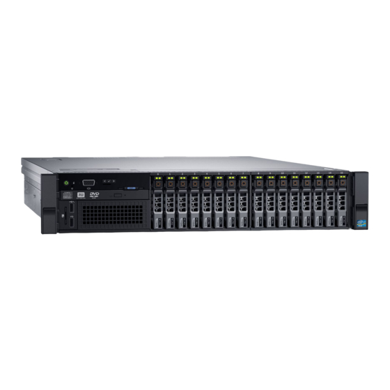
Dell PowerEdge R830 overview The Dell PowerEdge R830 is a 2U rack system with an 8-drive or 16-drive bay chassis and supports up to: • Four Intel Xeon E5-4600 v4 processors • 48 DIMMs • 16 hard drives or solid-state drives NOTE: Your system supports only hot swappable hard drives. - Page 9 Figure 2. Supported configurations for a four processor PowerEdge R830 system...
-
Page 10: Front Panel
Front panel The front panel provides access to the features available on the front of the server, such as the power button, NMI button, system identification tag, system identification button, and USB and VGA ports. The diagnostic LEDs or the LCD panel is prominently located on the front panel. -
Page 11: Lcd Panel
The LCD panel of your system provides system information, status, and error messages to indicate if the system is functioning correctly or if the system needs attention. For more information about error messages, see the Dell Event and Error Messages Reference Guide at Dell.com/openmanagemanuals >OpenManage software. - Page 12 LCD message with an SEL entry. Select Simple to view LCD error messages in a simplified user-friendly description. For more information about error messages, see the Dell Event and Error Messages Reference Guide at Dell.com/ openmanagemanuals > OpenManage software.
-
Page 13: Back Panel
Option Description Set home Select the default information to be displayed on the Home screen. See View menu section for the options and option items that can be set as the default on the Home screen. Related links View menu View menu NOTE: When you select an option in the View menu, you must confirm the option before proceeding to the next action. - Page 14 Enterprise port Use the iDRAC8 Enterprise port to remotely access iDRAC. For more information, see the Integrated Dell Remote Access Controller User’s Guide at Dell.com/idracmanuals. Video port Use the video/VGA port to connect a display to the system. For more information about the supported video/VGA port, see the Technical specifications section.
-
Page 15: Diagnostic Indicators On The Front Panel
Check the System Event Log or system messages for the specific issue. For more information about error • When the system is turned on. messages, see the Dell Event and Error Messages • When the system is in standby. Reference Guide at Dell.com/openmanagemanuals >... -
Page 16: Hard Drive Indicator Codes
Hard drive indicator codes Each hard drive carrier has an activity indicator and a status indicator. The indicators provide information about the current status of the hard drive. The activity LED indicates whether hard drive is currently in use or not. The status LED indicates the power condition of the hard drive. -
Page 17: Nic Indicator Codes
NIC indicator codes Each NIC on the back panel has an indicator that provides information about the network activity and link status. The activity LED indicates whether the NIC is currently connected or not. The link LED indicates the speed of the connected network. Figure 7. - Page 18 CAUTION: For AC PSUs, use only PSUs with the Extended Power Performance (EPP) label on the back. NOTE: Mixing PSUs from previous generations of Dell PowerEdge servers can result in a PSU mismatch condition or failure to turn the system on.
-
Page 19: Locating Service Tag Of Your System
Alternatively, the information may be on a sticker on the chassis of the system. This information is used by Dell to route support calls to the appropriate personnel. -
Page 20: Documentation Resources
Methods to download firmware and drivers section in this document. Managing your system For information about systems management Dell.com/openmanagemanuals software offered by Dell, see the Dell OpenManage Systems Management Overview Guide. For information about setting up, using, and Dell.com/openmanagemanuals troubleshooting OpenManage, see the Dell OpenManage Server Administrator User’s Guide. - Page 21 Task Document Location For understanding the features of Dell Lifecycle Dell.com/idracmanuals Controller (LCC), see the Dell Lifecycle Controller User’s Guide. For information about partner programs Dell.com/ enterprise systems management, see the omconnectionsenterprisesystemsmanagement OpenManage Connections Enterprise Systems Management documents. For information about viewing inventory, Dell.com/esmmanuals...
-
Page 22: Technical Specifications
Technical specifications The technical and environmental specifications of your system are outlined in this section. System dimensions Figure 9. Dimensions of the PowerEdge R830 system Table 9. Dimensions of the PowerEdge R830 system Z (with bezel) Zb (without Za (with bezel) -
Page 23: Processor Specifications
The PowerEdge R830 system supports CR 2032 3.0-V lithium coin cell system battery. Expansion bus specifications The PowerEdge R830 system supports PCI express (PCIe) generation 3 expansion cards, which need to be installed on the system board using expansion card risers. This system supports three types of expansion card risers. -
Page 24: Optical Drive
9-pin connector, Data Terminal Equipment (DTE), 16550-compliant. VGA ports The Video Graphic Array (VGA) port enables you to connect the system to a VGA display. The PowerEdge R830 system supports two 15-pin VGA ports on the front and back panels. -
Page 25: Environmental Specifications
8, 16, 32 1280x1024 60,75 8, 16, 32 1440x900 8, 16, 32 Environmental specifications NOTE: For additional information about environmental measurements for specific system configurations, see Dell.com/ environmental_datasheets. Table 16. Temperature specifications Temperature Specifications Storage –40°C to 65°C (–40°F to 149°F) Continuous operation (for altitude less than 950 m or 5°C to 40°C (41°F to 104°F) with no direct sunlight on the equipment. -
Page 26: Particulate And Gaseous Contamination Specifications
Table 20. Maximum altitude specifications Maximum altitude Specifications 3048 m (10,000 ft) Operating Storage 12,000 m (39,370 ft) Table 21. Operating temperature de-rating specifications Operating temperature de-rating Specifications Up to 35°C (95°F) Maximum temperature is reduced by 1°C/300 m (1°F/547 ft) above 950 m (3,117 ft). -
Page 27: Standard Operating Temperature
PCIe Cards are not supported on slot 1 and 2. • A maximum of eight hard drives are supported on systems with a 135 W processor. • Redundant power supplies are required. • Non-Dell qualified peripheral cards and/or peripheral cards greater than 25 W are not supported. -
Page 28: Initial System Setup And Configuration
Turn on the attached peripherals. iDRAC configuration The Integrated Dell Remote Access Controller (iDRAC) is designed to make system administrators more productive and improve the overall availability of Dell systems. iDRAC alerts administrators to system issues, helps them perform remote system management, and reduces the need for physical access to the system. -
Page 29: Options To Install The Operating System
The default user name and password are root and calvin. You can also log in by using Single Sign-On or Smart Card. NOTE: You must have iDRAC credentials to log in to iDRAC. For more information about logging in to iDRAC and iDRAC licenses, see the Integrated Dell Remote Access Controller User's Guide at Dell.com/idracmanuals. - Page 30 NOTE: If you do not have the Service Tag, select Detect My Product to allow the system to automatically detect your Service Tag, or under General support, navigate to your product. Click Drivers & Downloads. The drivers that are applicable to your selection are displayed. Download the drivers to a USB drive, CD, or DVD.
-
Page 31: Pre-Operating System Management Applications
Options to manage the pre-operating system applications Your system has the following options to manage the pre-operating system applications: • System Setup • Boot Manager • Dell Lifecycle Controller • Preboot Execution Environment (PXE) Related links System Setup Boot Manager Dell Lifecycle Controller... -
Page 32: System Setup Details
The iDRAC settings utility is an interface to set up and configure the iDRAC parameters by using UEFI (Unified Extensible Firmware Interface). You can enable or disable various iDRAC parameters by using the iDRAC settings utility. For more information about this utility, see Integrated Dell Remote Access Controller User’s Guide at Dell.com/idracmanuals. - Page 33 Related links System BIOS System BIOS Settings details System BIOS Settings details The System BIOS Settings screen details are explained as follows: Option Description System Information Specifies information about the system such as the system model name, BIOS version, and Service Tag. Memory Settings Specifies information and options related to the installed memory.
- Page 34 Related links Boot Settings Boot Settings details Choosing the system boot mode Changing the boot order Boot Settings details The Boot Settings screen details are explained as follows: Option Description Boot Mode Enables you to set the boot mode of the system. CAUTION: Switching the boot mode may prevent the system from booting if the operating system is not installed in the same boot mode.
- Page 35 NOTE: Operating systems must be UEFI-compatible to be installed from the UEFI boot mode. DOS and 32-bit operating systems do not support UEFI and can only be installed from the BIOS boot mode. NOTE: For the latest information about supported operating systems, go to Dell.com/ossupport. Related links...
- Page 36 Network Settings screen details The Network Settings screen details are explained as follows: Option Description PXE Device n (n = 1 Enables or disables the device. When enabled, a UEFI boot option is created for the device. to 4) PXE Device n Enables you to control the configuration of the PXE device.
- Page 37 System Security You can use the System Security screen to perform specific functions such as setting the system password, setup password and disabling the power button. Related links System Security Settings details Operating with a setup password enabled System BIOS Viewing System Security Creating a system and setup password Using your system password to secure your system...
- Page 38 Option Description Intel TXT Enables or disables the Intel Trusted Execution Technology (TXT) option. To enable the Intel TXT option, virtualization technology and TPM Security must be enabled with Pre-boot measurements. This option is set to Off by default. Power Button Enables or disables the power button on the front of the system.
- Page 39 A message prompts you to save the changes. NOTE: Password protection does not take effect until the system reboots. Related links System Security Using your system password to secure your system If you have assigned a setup password, the system accepts your setup password as an alternate system password. Steps Turn on or reboot your system.
- Page 40 Related links System Security System Information You can use the System Information screen to view system properties such as Service Tag, system model name, and the BIOS version. Related links System Information details System BIOS Viewing System Information Viewing System Information To view the System Information screen, perform the following steps: Turn on, or restart your system.
- Page 41 Specifies the memory operating mode. The options available are Optimizer Mode, Advanced ECC Mode, Mode Mirror Mode, Spare Mode, Spare with Advanced ECC Mode, Dell Fault Resilient Mode and Dell NUMA Fault Resilient Mode. This option is set to Optimizer Mode by default.
- Page 42 Option Description Snoop Mode Specifies the Snoop Mode options. The Snoop Mode options available are Home Snoop, Early Snoop, and Cluster on Die. This option is set to Early Snoop by default. This field is available only when the Node Interleaving is set to Disabled.
- Page 43 NOTE: This option is only available on certain stock keeping units (SKUs) of the processors. X2Apic Mode Enables or disables the X2Apic mode. Dell Controlled Controls the turbo engagement. Enable this option only when System Profile is set to Performance. Turbo NOTE: Depending on the number of installed CPUs, there may be up to four processor listings.
- Page 44 Related links SATA Settings details System BIOS Viewing SATA Settings Viewing SATA Settings To view the SATA Settings screen, perform the following steps: Turn on, or restart your system. Press F2 immediately after you see the following message: F2 = System Setup NOTE: If your operating system begins to load before you press F2, wait for the system to finish booting, and then restart your system and try again.
- Page 45 Option Description Port C Sets the drive type of the selected device. For Embedded SATA settings in ATA mode, set this field to Auto to enable BIOS support. Set it to OFF to turn off BIOS support. For AHCI or RAID mode, BIOS support is always enabled. Option Description Model...
- Page 46 Option Description Option Description Drive Type Specifies the type of drive attached to the SATA port. Capacity Specifies the total capacity of the hard drive. This field is undefined for removable media devices such as optical drives. Port H Sets the drive type of the selected device. For Embedded SATA settings in ATA mode, set this field to Auto to enable BIOS support.
- Page 47 Viewing Integrated Devices To view the Integrated Devices screen, perform the following steps: Turn on, or restart your system. Press F2 immediately after you see the following message: F2 = System Setup NOTE: If your operating system begins to load before you press F2, wait for the system to finish booting, and then restart your system and try again.
- Page 48 Option Description OS Watchdog If your system stops responding, this watchdog timer aids in the recovery of your operating system. When Timer this option is set to Enabled, the operating system initializes the timer. When this option is set to Disabled (the default), the timer does not have any effect on the system.
- Page 49 You can only change the rest of the options if the mode is set to Custom. This option is set to Performance Per Watt Optimized (DAPC) by default. DAPC is Dell Active Power Controller.
- Page 50 Option Description NOTE: All the parameters on the system profile setting screen are available only when the System Profile option is set to Custom. CPU Power Sets the CPU power management. This option is set to System DBPM (DAPC) by default. DBPM is Management Demand-Based Power Management.
- Page 51 Miscellaneous Settings You can use the Miscellaneous Settings screen to perform specific functions such as updating the asset tag and changing the system date and time. Related links Miscellaneous Settings details System BIOS Viewing Miscellaneous Settings Viewing Miscellaneous Settings To view the Miscellaneous Settings screen, perform the following steps: Turn on, or restart your system.
-
Page 52: Idrac Settings Utility
NOTE: Accessing some of the features on the iDRAC settings utility needs the iDRAC Enterprise License upgrade. For more information about using iDRAC, see Dell Integrated Dell Remote Access Controller User's Guide at Dell.com/idracmanuals. Related links... -
Page 53: Dell Lifecycle Controller
Dell Lifecycle Controller Dell Lifecycle Controller (LC) provides advanced embedded systems management capabilities including system deployment, configuration, update, maintenance, and diagnosis. LC is delivered as part of the iDRAC out-of-band solution and Dell system embedded Unified Extensible Firmware Interface (UEFI) applications. -
Page 54: Pxe Boot
Menu item Description Launch Lifecycle Exits the Boot Manager and invokes the Dell Lifecycle Controller program. Controller System Utilities Enables you to launch System Utilities menu such as System Diagnostics and UEFI shell. Related links Boot Manager Viewing Boot Manager One-shot BIOS boot menu One-shot BIOS boot menu enables you to select a boot device to boot from. -
Page 55: Installing And Removing System Components
Damage due to servicing that is not authorized by Dell is not covered by your warranty. Read and follow the safety instructions that are shipped with your product. -
Page 56: Recommended Tools
Related links Safety instructions Installing the system cover Recommended tools You need the following tools to perform the removal and installation procedures: • Key to the bezel lock. The key is needed only if your system includes a bezel. • Phillips #2 screwdriver •... -
Page 57: Installing The Optional Front Bezel
Figure 10. Removing the optional front bezel release latch bezel lock front bezel Related links Safety instructions Installing the optional front bezel Installing the optional front bezel Prerequisites Follow the safety guidelines listed in the Safety instructions section. Steps Locate and remove the bezel key. NOTE: The bezel key is attached to the back of the bezel. -
Page 58: System Cover
Figure 11. Installing the optional front bezel bezel lock front bezel Related links Safety instructions System cover The system cover protects the components inside the system and helps in maintaining air flow inside the system. Removing the system cover enables the intrusion switch that aids in maintaining system security. Removing the system cover Prerequisites Follow the safety guidelines listed in the Safety instructions section. -
Page 59: Installing The System Cover
Figure 12. Removing the system cover system cover latch latch release lock Next steps Install the system cover. Related links Safety instructions Removing the optional front bezel Installing the system cover Installing the system cover Prerequisites Follow the safety guidelines listed in the Safety instructions section. Ensure that all internal cables are connected and placed out of the way, and no tools or extra parts are left inside the system. -
Page 60: Inside The System
Damage due to servicing that is not authorized by Dell is not covered by your warranty. Read and follow the safety instructions that are shipped with your product. - Page 61 Figure 14. Inside the system — Two processor system cooling fans (6) processors (2) DIMMs (12) power supply unit (PSU) (2) PSU connector riser 3 riser 2 riser 1 DIMMs (12)
-
Page 62: Processor Expansion Module (Optional)
Damage due to servicing that is not authorized by Dell is not covered by your warranty. Read and follow the safety instructions that are shipped with your product. - Page 63 Follow the procedure listed in the Before working inside your system section. Steps Lift the release lever on the PEM until the PEM disengages from the chassis. Figure 16. Disengaging the PEM processor expansion module release lever Holding the release lever and a support pin, lift the PEM away from the chassis.
- Page 64 Figure 17. Removing the PEM processor expansion module release lever If you are removing the PEM permanently, install a filler bracket over the QPI connector and install a cooling shroud. NOTE: You must install a filler bracket over the QPI connector to maintain the Federal Communications Commission (FCC) certification of the system.
-
Page 65: Installing The Processor Expansion Module
Damage due to servicing that is not authorized by Dell is not covered by your warranty. Read and follow the safety instructions that are shipped with your product. - Page 66 Figure 19. Removing the filler bracket from the QPI connector filler bracket standoff (2) If applicable, remove the PEM power connector cap. By holding the support pin and the release lever, align the alignment guides on the PEM with the alignment guides on the chassis, and lower the PEM into the chassis.
-
Page 67: Cooling Shroud
Damage due to servicing that is not authorized by Dell is not covered by your warranty. Read and follow the safety instructions that are shipped with your product. -
Page 68: Installing The Cooling Shroud
Damage due to servicing that is not authorized by Dell is not covered by your warranty. Read and follow the safety... -
Page 69: Cooling Fans
Follow the safety guidelines listed in the Safety instructions section. Follow the procedure listed in the Before working inside your system section. If applicable, route the cables inside the system along the chassis wall and secure the cables by using the cable-securing bracket. -
Page 70: Removing A Cooling Fan
Damage due to servicing that is not authorized by Dell is not covered by your warranty. Read and follow the safety instructions that are shipped with your product. -
Page 71: Installing A Cooling Fan
Damage due to servicing that is not authorized by Dell is not covered by your warranty. Read and follow the safety instructions that are shipped with your product. -
Page 72: Cooling Fan Assembly
Damage due to servicing that is not authorized by Dell is not covered by your warranty. Read and follow the safety instructions that are shipped with your product. -
Page 73: Installing The Cooling Fan Assembly
Damage due to servicing that is not authorized by Dell is not covered by your warranty. Read and follow the safety instructions that are shipped with your product. -
Page 74: System Memory
cooling fan connector (6) guide pin on the chassis (6) Next steps Follow the procedure listed in the After working inside your system section. Related links Safety instructions Before working inside your system After working inside your system System memory The system supports DDR4 registered DIMMs (RDIMMs) and load reduced DIMMs (LRDIMMs). - Page 75 Figure 28. Memory socket locations...
- Page 76 Figure 29. Memory socket locations on the processor expansion module Memory channels are organized as follows: Table 28. Memory channels Processor Channel 0 Channel 1 Channel 2 Channel 3 Processor 1 Slots A1, A5, and A9 Slots A2, A6, and A10 Slots A3, A7, and A11 Slots A4, A8, and A12 Processor...
-
Page 77: General Memory Module Installation Guidelines
DIMM Type DIMMs Populated/ Operating Frequency (in Maximum DIMM Rank/ Voltage Channel MT/s) Channel 1866 Dual rank or single rank LRDIMM 2400, 2133, 1866 Quad rank 1.2 V 2400, 2133, 1866 Quad rank 2133, 1866 Quad rank General memory module installation guidelines NOTE: Memory configurations that fail to observe these guidelines can prevent your system from booting, stop responding during memory configuration, or operating with reduced memory. -
Page 78: Sample Memory Configurations
Memory sparing NOTE: To use memory sparing, this feature must be enabled in System Setup. In this mode, one rank per channel is reserved as a spare. If persistent correctable errors are detected on a rank, the data from this rank is copied to the spare rank, and the failed rank is disabled. - Page 79 System Capacity (in DIMM Size (in GB) Number of DIMM rank, organization, DIMM Slot Population DIMMs and frequency 1R x8, 2400 MT/s 1R x8, 1866 MT/s A1, A2, A3, A4, A5, A6, A7, A8, B1, B2, B3, B4, B5, B6, B7, B8 1R x8, 2133 MT/s 1R x8, 2400 MT/s 1R x8, 1866 MT/s...
- Page 80 System Capacity (in DIMM Size (in GB) Number of DIMM rank, organization, DIMM Slot Population DIMMs and frequency NOTE: 16 GB DIMMs must be installed in the slots numbered A1, A2, A3, A4, B1, B2, B3, and B4 and 8 GB DIMMs must be installed in slots A5, A6, B5 and B6.
- Page 81 System Capacity (in DIMM Size (in GB) Number of DIMM rank, organization, DIMM Slot Population DIMMs and frequency 4R x4, 1866 MT/s A1, A2, A3, A4, A5, A6, A7, A8, A9, 1536 A10, A11, A12, B1, B2, B3, B4, B5, 4R x4, 2133 MT/s B6, B7, B8, B9, B10, B11, B12 4R x4, 2400 MT/s...
- Page 82 System Capacity (in DIMM Size (in GB) Number of Organization and Speed DIMM Slot Population DIMMs 1R x8, 1866 MT/s A1, A2, A3, A4, A5, A6, B1, B2, B3, B4, B5, B6, C1, C2, C3, C4, C5, 1R x8, 2133 MT/s C6, D1, D2, D3, D4, D5, D6 1R x8, 2400 MT/s 1R x8, 1866 MT/s...
-
Page 83: Removing Memory Modules
Damage due to servicing that is not authorized by Dell is not covered by your warranty. Read and follow the safety instructions that are shipped with your product. -
Page 84: Installing Memory Modules
Steps Locate the appropriate memory module socket. CAUTION: Handle each memory module only by the card edges, ensuring not to touch the middle of the memory module or metallic contacts. To release the memory module from the socket, simultaneously press the ejectors on both ends of the memory module socket. Lift and remove the memory module from the system. - Page 85 Damage due to servicing that is not authorized by Dell is not covered by your warranty. Read and follow the safety instructions that are shipped with your product.
-
Page 86: Processors And Heat Sinks
Run the system memory test in system diagnostics. Related links Safety instructions Before working inside your system Installing the cooling shroud After working inside your system Processors and heat sinks Use the following procedure when: • Removing and installing a heat sink •... -
Page 87: Removing A Processor
Damage due to servicing that is not authorized by Dell is not covered by your warranty. Read and follow the safety instructions that are shipped with your product. - Page 88 WARNING: The processor is hot to touch for some time after the system has been powered down. Allow the processor to cool before removing it. CAUTION: The processor is held in its socket under strong pressure. Be aware that the release lever can spring up suddenly if not firmly grasped.
- Page 89 processor open first socket release lever unlock icon Figure 34. Removing a processor close first socket-release lever pin-1 indicator of processor processor slot (4) processor shield open first socket-release lever socket socket keys (4) Next steps Replace the processor(s). Install the heat sink. Reinstall the cooling shroud.
-
Page 90: Installing A Processor
Damage due to servicing that is not authorized by Dell is not covered by your warranty. Read and follow the safety instructions that are shipped with your product. - Page 91 Figure 35. Installing a processor socket-release lever 1 pin–1 corner of the processor processor slot (4) processor shield socket-release lever 2 processor socket tab (4) Next steps NOTE: Ensure that you install the heat sink after you install the processor. The heat sink is necessary to maintain proper thermal conditions.
-
Page 92: Installing A Heat Sink
Damage due to servicing that is not authorized by Dell is not covered by your warranty. Read and follow the safety instructions that are shipped with your product. -
Page 93: Power Supply Units
NOTE: Do not over-tighten the heat sink retention screws when installing the heat sink. To prevent over-tightening, tighten the retention screw until resistance is felt, and stop after the screw is seated. The screw tension should not be more than 6 in-lb (6.9 kg-cm). Repeat the procedure for the remaining two screws. -
Page 94: Hot Spare Feature
Damage due to servicing that is not authorized by Dell is not covered by your warranty. Read and follow the safety instructions that are shipped with your product. -
Page 95: Installing The Power Supply Unit Blank
Damage due to servicing that is not authorized by Dell is not covered by your warranty. Read and follow the safety instructions that are shipped with your product. -
Page 96: Removing An Ac Power Supply Unit
Damage due to servicing that is not authorized by Dell is not covered by your warranty. Read and follow the safety instructions that are shipped with your product. -
Page 97: Installing An Ac Power Supply Unit
Damage due to servicing that is not authorized by Dell is not covered by your warranty. Read and follow the safety instructions that are shipped with your product. -
Page 98: Integrated Storage Controller Card
Damage due to servicing that is not authorized by Dell is not covered by your warranty. Read and follow the safety instructions that are shipped with your product. - Page 99 Figure 42. Removing the integrated storage controller card storage controller card expansion card latch riser card 3 SAS cable (2) Disconnect the cables connected to the card by performing the following steps: a. Press the latch on the SAS cable connector. b.
-
Page 100: Installing The Integrated Storage Controller Card
Damage due to servicing that is not authorized by Dell is not covered by your warranty. Read and follow the safety instructions that are shipped with your product. -
Page 101: Expansion Cards And Expansion Card Riser
NOTE: Ensure that you connect the cable according to the connector labels on the cable. The cable does not function properly if reversed. Connect the SAS data cable to the system board. Next steps Install the expansion card riser 1. If applicable, install the cooling shroud. -
Page 102: Removing Expansion Card Risers
Damage due to servicing that is not authorized by Dell is not covered by your warranty. Read and follow the safety instructions that are shipped with your product. - Page 103 Steps Holding the slots on the expansion card riser, lift the riser from the riser connector on the system board. To remove expansion card riser 3, hold the edges of the expansion card riser. NOTE: To ensure proper system cooling, the riser blank must be installed in the appropriate riser slot. Remove the riser blank only if you are installing a riser.
- Page 104 Figure 45. Connectors on the expansion card riser 1 expansion card connector slot 1 expansion card connector slot 2 Figure 46. Removing the expansion card riser 2 expansion card riser 2 touch point (2) riser guide (right) riser guide (left) expansion card riser 2 connector...
- Page 105 Figure 47. Connectors on the expansion card riser 2 expansion card connector slot 3 expansion card connector slot 4 expansion card connector slot 5 Figure 48. Removing the expansion card riser 3 expansion card riser 3 guide pin on the chassis expansion card riser 3 connector riser guide (right)
-
Page 106: Installing Expansion Card Risers
Damage due to servicing that is not authorized by Dell is not covered by your warranty. Read and follow the safety instructions that are shipped with your product. - Page 107 Figure 50. Installing the expansion card riser 1 expansion card riser 1 touch point (2) riser guide (back) expansion card riser 1 connector riser guide-front...
- Page 108 Figure 51. Installing the expansion card riser 2 expansion card riser 2 touch point (2) riser guide (right) riser guide (left) expansion card riser 2 connector...
-
Page 109: Removing An Expansion Card From Expansion Card Riser 1
Damage due to servicing that is not authorized by Dell is not covered by your warranty. Read and follow the safety instructions that are shipped with your product. - Page 110 Steps Disconnect any cables connected to the expansion card. Press the expansion card retention latch and pull it open from the expansion card riser. Pull the expansion card release latch open. Hold the expansion card by its edges, and remove it from the expansion card connector. If you are removing the card permanently, install a metal filler bracket over the empty expansion slot opening and close the expansion card latch.
-
Page 111: Installing An Expansion Card Into Expansion Card Riser 1
Damage due to servicing that is not authorized by Dell is not covered by your warranty. Read and follow the safety instructions that are shipped with your product. -
Page 112: Removing An Expansion Card From Expansion Card Riser 2
Damage due to servicing that is not authorized by Dell is not covered by your warranty. Read and follow the safety instructions that are shipped with your product. -
Page 113: Installing An Expansion Card Into Expansion Card Riser 2
Damage due to servicing that is not authorized by Dell is not covered by your warranty. Read and follow the safety instructions that are shipped with your product. - Page 114 Steps If applicable, unpack the expansion card and prepare it for installation. For instructions, see the documentation accompanying the card. Open the expansion card latch and remove the filler bracket. Holding the card by its edges, insert the card edge connector firmly into the expansion card connector until the card is fully seated.
-
Page 115: Removing An Expansion Card From The Expansion Card Riser 3
Damage due to servicing that is not authorized by Dell is not covered by your warranty. Read and follow the safety instructions that are shipped with your product. -
Page 116: Installing An Expansion Card Into Expansion Card Riser 3
Damage due to servicing that is not authorized by Dell is not covered by your warranty. Read and follow the safety instructions that are shipped with your product. - Page 117 Steps If applicable, unpack the expansion card and prepare it for installation. For instructions, see the documentation accompanying the card. Open the expansion card retention latch. Holding the card by its edges, insert the card-edge connector firmly into the expansion card connector until the card is fully seated.
-
Page 118: Internal Dual Sd Module (Optional)
Figure 60. Installing a full-height expansion card into the expansion card riser 3 expansion card holder expansion card expansion card connector expansion card riser 3 Next steps If applicable, connect any cables to the expansion card. Install any device drivers needed for the card as described in the documentation for the card. Follow the procedure listed in the After working inside your system section. -
Page 119: Removing An Internal Sd Card
Damage due to servicing that is not authorized by Dell is not covered by your warranty. Read and follow the safety instructions that are shipped with your product. -
Page 120: Installing An Internal Sd Card
Damage due to servicing that is not authorized by Dell is not covered by your warranty. Read and follow the safety instructions that are shipped with your product. -
Page 121: Removing The Optional Internal Dual Sd Module
Damage due to servicing that is not authorized by Dell is not covered by your warranty. Read and follow the safety instructions that are shipped with your product. -
Page 122: Installing The Optional Internal Dual Sd Module
Damage due to servicing that is not authorized by Dell is not covered by your warranty. Read and follow the safety instructions that are shipped with your product. -
Page 123: Network Daughter Card
Damage due to servicing that is not authorized by Dell is not covered by your warranty. Read and follow the safety... - Page 124 Steps Loosen the captive screws that secure the network daughter card (NDC) to the system board. Hold the NDC by the edges on either side of the touch point, and lift the card to disengage it from the connector on the system board.
-
Page 125: Installing The Network Daughter Card
Damage due to servicing that is not authorized by Dell is not covered by your warranty. Read and follow the safety instructions that are shipped with your product. -
Page 126: Internal Usb Memory Key (Optional)
Damage due to servicing that is not authorized by Dell is not covered by your warranty. Read and follow the safety instructions that are shipped with your product. -
Page 127: System Battery
Damage due to servicing that is not authorized by Dell is not covered by your warranty. Read and follow the safety instructions that are shipped with your product. -
Page 128: Hard Drives
Figure 69. Removing the system battery system battery system battery slot To install a new system battery, hold the battery with the "+" facing up and slide it under the securing tabs. Press the battery into the connector until it snaps into place. Figure 70. -
Page 129: Removing A Hot Swappable Hard Drive Or Solid State Drive
Damage due to servicing that is not authorized by Dell is not covered by your warranty. Read and follow the safety instructions that came with the product. -
Page 130: Installing A Hot Swappable Hard Drive Or Solid State Drive
Damage due to servicing that is not authorized by Dell is not covered by your warranty. Read and follow the safety instructions that are shipped with your product. -
Page 131: Removing A 2.5-Inch Hard Drive Blank
Damage due to servicing that is not authorized by Dell is not covered by your warranty. Read and follow the safety instructions that came with the product. -
Page 132: Installing A 2.5-Inch Hard Drive Blank
Figure 73. Removing a 2.5-inch hard drive blank hard drive blank release button Related links Safety instructions Removing the optional front bezel Installing a 2.5-inch hard drive blank Installing a 2.5-inch hard drive blank Prerequisites Follow the safety guidelines listed in the Safety instructions section. If installed, remove the front bezel. -
Page 133: Removing A Hard Drive Or A Solid State Drive From A Hard Drive Carrier
Damage due to servicing that is not authorized by Dell is not covered by your warranty. Read and follow the safety instructions that are shipped with your product. -
Page 134: Optical Drive (Optional)
Damage due to servicing that is not authorized by Dell is not covered by your warranty. Read and follow the safety instructions that are shipped with your product. -
Page 135: Installing The Optical Drive
Damage due to servicing that is not authorized by Dell is not covered by your warranty. Read and follow the safety instructions that are shipped with your product. -
Page 136: Removing The Slim Optical Drive Blank
Damage due to servicing that is not authorized by Dell is not covered by your warranty. Read and follow the safety instructions that are shipped with your product. -
Page 137: Installing The Slim Optical Drive Blank
Damage due to servicing that is not authorized by Dell is not covered by your warranty. Read and follow the safety instructions that are shipped with your product. -
Page 138: Hard Drive Backplane
Damage due to servicing that is not authorized by Dell is not covered by your warranty. Read and follow the safety instructions that are shipped with your product. - Page 139 Figure 81. Removing the 2.5 inch (x16) SAS/SATA backplane hooks (3) securing slots (3) hard drive backplane backplane power cable backplane signal cable release tab (2) SAS cable (2) mini SAS connector (2) hard drive connector on the backplane...
- Page 140 Figure 82. Cabling diagram—2.5 inch (x16) SAS/SATA backplane signal connector on the backplane cable retention bracket SAS B connector on the PERC card SAS A connector on the PERC card system board cable retention bracket signal connector on the system board SAS B connector on the backplane SAS A connector on the backplane 10.
- Page 141 Figure 83. Removing the 2.5 inch (x8) SAS/SATA backplane hard drive connector on the backplane hard drive backplane hooks (3) securing slots (3) release tab backplane power cable SAS cable (2) backplane signal cable mini SAS connector (2)
- Page 142 Figure 84. Cabling diagram—2.5 inch (x8) SAS/SATA backplane signal connector on the backplane cable retention bracket SAS B connector on the PERC card SAS A connector on the PERC card system board cable retention bracket signal connector on the system board SAS B connector on the backplane hard drive backplane 10.
-
Page 143: Installing The Hard Drive Backplane
Damage due to servicing that is not authorized by Dell is not covered by your warranty. Read and follow the safety instructions that are shipped with your product. -
Page 144: Control Panel
Damage due to servicing that is not authorized by Dell is not covered by your warranty. Read and follow the safety... - Page 145 Steps Using a Phillips #2 screwdriver, remove the screw(s) securing the control panel to the chassis. CAUTION: Do not use excessive force when removing the control panel as it can damage the connectors. Remove all the cables connecting the control panel to the system board. NOTE: Ensure that you remove the cooling fan assembly before you remove the USB power cable.
- Page 146 Figure 88. Removing the vFlash connector/USB connector module 1. vFlash connector/USB connector module 2. screw (2) 3. control panel connector cable Locate and press the tabs on the information tag. Push the information tag out of the slot to remove it from the control panel. NOTE: Retain the information tag for replacement in the new control panel.
-
Page 147: Installing The Control Panel
Damage due to servicing that is not authorized by Dell is not covered by your warranty. Read and follow the safety instructions that are shipped with your product. - Page 148 NOTE: Ensure that you remove the cooling fan assembly before install the USB power cable. Slide the control panel into the slot in the chassis and secure the module with the screws. Figure 91. Installing the control panel control panel screw (2) control panel connector cable USB connector cable...
-
Page 149: System Board
Damage due to servicing that is not authorized by Dell is not covered by your warranty. Read and follow the safety instructions that are shipped with your product. - Page 150 CAUTION: Do not lift the system board by holding a memory module, processor, or other components. Hold the system board holder, lift the blue release pin, lift the system board, and then slide it toward the front of the chassis. Sliding the system board toward the front of the chassis disengages the connectors from the back of the chassis slots.
-
Page 151: Installing The System Board
Damage due to servicing that is not authorized by Dell is not covered by your warranty. Read and follow the safety instructions that are shipped with your product. - Page 152 Enter the system Service Tag manually. For more information, see the Entering the system Service Tag section. Import your new or existing iDRAC Enterprise license. For more information, see Integrated Dell Remote Access Controller User's Guide, at Dell.com/esmmanuals.
-
Page 153: Trusted Platform Module
Damage due to servicing that is not authorized by Dell is not covered by your warranty. Read and follow the safety instructions that are shipped with your product. -
Page 154: Initializing The Tpm For Bitlocker Users
Steps Locate the TPM connector on the system board. NOTE: To locate the TPM connector on the system board, see the System board connectors section. Align the edge connectors on the TPM with the slot on the TPM connector. Insert the TPM into the TPM connector such that the plastic rivet aligns with the slot on the system board. Press the plastic rivet until the rivet snaps into place. -
Page 155: Using System Diagnostics
Using system diagnostics If you experience a problem with your system, run the system diagnostics before contacting Dell for technical assistance. The purpose of running system diagnostics is to test your system hardware without requiring additional equipment or risking data loss. If you are unable to fix the problem yourself, service and support personnel can use the diagnostics results to help you solve the problem. -
Page 156: Menu Description
Menu Description Results Displays the results of all tests that are run. System health Provides the current overview of the system performance. Event log Displays a time-stamped log of the results of all tests run on the system. This is displayed if at least one event description is recorded. -
Page 157: Jumpers And Connectors
Jumpers and connectors System board jumper settings Table 36. System board jumper settings Jumper Setting Description PWRD_EN The password reset feature is enabled (pins 2–4). BIOS local access is unlocked at the next AC power cycle. The password reset feature is disabled (pins 4–6). NVRAM_CLR The configuration settings are retained at the next system boot (pins 3–5). -
Page 158: System Board Connectors
System Board Connectors Figure 96. System Board Connectors Table 37. System board connectors and descriptions Item Connector Description J_P12V_PWR Processor expansion module power connectors PSU 2 power connector J_P12V_PWR Processor expansion module power connectors PSU 1 power connector IO_RISER3 Riser 3 connector CYC_ID System identification button System identification connector... - Page 159 Item Connector Description USB_REAR_2 USB rear connector 2 USB_REAR_1 USB rear connector 1 IO_RISER2 Riser 2 connector USB_INT Internal USB connector SPIVU SPIVU connector IO_RISER1 Riser 1 connector IDSDM Internal Dual SD Module QPI CONNECTOR QPI connector BATTERY System battery SATA_CD Optical drive SATA connector FP_USB...
-
Page 160: Disabling A Forgotten Password
Damage due to servicing that is not authorized by Dell is not covered by your warranty. Read and follow the safety instructions that are shipped with your product. - Page 161 Turn off the system, including any attached peripherals, and disconnect the system from the electrical outlet. Remove the system cover. Move the jumper on the system board jumper from pins 2 and 4 to pins 4 and 6. Install the system cover. 10.
-
Page 162: Troubleshooting Your System
Damage due to servicing that is not authorized by Dell is not covered by your warranty. Read and follow the safety instructions that are shipped with your product. -
Page 163: Troubleshooting A Usb Device
Getting help System Setup Troubleshooting iDRAC Direct (USB XML configuration) For information about USB storage device and server configuration, see the Integrated Dell Remote Access Controller User's Guide at Dell.com/idracmanuals. Steps Ensure that your USB storage device is connected to the front USB Management Port, identified by icon. -
Page 164: Troubleshooting Idrac Direct (Laptop Connection)
Related links Getting help Troubleshooting iDRAC Direct (Laptop connection) For information about USB laptop connection and server configuration, see the Integrated Dell Remote Access Controller User's Guide at Dell.com/idracmanuals. Steps Ensure that your laptop is connected to the front USB Management Port, identified by icon with a USB Type A/A cable. -
Page 165: Troubleshooting A Wet System
Damage due to servicing that is not authorized by Dell is not covered by your warranty. Read and follow the safety instructions that are shipped with your product. -
Page 166: Troubleshooting A Damaged System
Damage due to servicing that is not authorized by Dell is not covered by your warranty. Read and follow the safety instructions that are shipped with your product. -
Page 167: Troubleshooting Power Supply Units
Damage due to servicing that is not authorized by Dell is not covered by your warranty. Read and follow the safety instructions that are shipped with your product. -
Page 168: Troubleshooting Cooling Fans
Damage due to servicing that is not authorized by Dell is not covered by your warranty. Read and follow the safety instructions that are shipped with your product. -
Page 169: Troubleshooting An Internal Usb Key
Damage due to servicing that is not authorized by Dell is not covered by your warranty. Read and follow the safety instructions that are shipped with your product. -
Page 170: Troubleshooting An Sd Card
Damage due to servicing that is not authorized by Dell is not covered by your warranty. Read and follow the safety instructions that are shipped with your product. -
Page 171: Troubleshooting A Tape Backup Unit
Damage due to servicing that is not authorized by Dell is not covered by your warranty. Read and follow the safety instructions that are shipped with your product. -
Page 172: Troubleshooting A Storage Controller
Damage due to servicing that is not authorized by Dell is not covered by your warranty. Read and follow the safety instructions that are shipped with your product. -
Page 173: Troubleshooting Expansion Cards
Damage due to servicing that is not authorized by Dell is not covered by your warranty. Read and follow the safety instructions that are shipped with your product. -
Page 174: Troubleshooting Processors
Damage due to servicing that is not authorized by Dell is not covered by your warranty. Read and follow the safety instructions that are shipped with your product. -
Page 175: Getting Help
The Contact Technical Support page is displayed with details to call, chat, or e-mail the Dell Global Technical Support team. Documentation feedback You can rate the documentation or write your feedback on any of our Dell documentation pages and click Send Feedback to send your feedback. -
Page 176: Quick Resource Locator For R830
Steps Go to Dell.com/QRL and navigate to your specific product or Use your smartphone or tablet to scan the model-specific Quick Resource (QR) code on your Dell PowerEdge system or in the Quick Resource Locator section. Quick Resource Locator for R830...