Table of Contents
Advertisement
Quick Links
Download this manual
See also:
User Manual
Advertisement
Table of Contents

Related Manuals for Asus P750


Summary of Contents for Asus P750
- Page 1 GTC ■ Service Manual ASUS P750 Repair Guide (Level 3 4) Ver 1.0b ASUS Proprietary...
-
Page 2: Table Of Contents
6.2.7 Camera Test & VGA Camera............18 6.2.8 Check SIM ..................20 6.2.9 Battery Test..................21 6.2.10 SDRAM Test ..................22 6.2.12 Turn On/Off Radio................25 6.2.13 Version Check.................. 27 6.2.14 Keypad Test ..................27 6.2.15 WiFi Board-Level Test ..............29 ASUS Proprietary... - Page 3 10.3 TX M .................. 43 EASUREMENT 10.4 T :..................45 EST PROCEDURE 10.5 WCDMA RX ..................51 10.6 WCDMA RX P ............53 EASUREMENT 10.7 RX T ................54 EST PROCEDURE 10.8 WCDMA PA P .............. 60 OWER ONTROL ASUS Proprietary...
-
Page 4: Product General Specification
Expansion Slot Micro-SD (SDHC supports) GPS (SiRF III with internal antenna), AGPS (need to co-work with local operators) , TMC (optional cable) JAVA J2ME (CLDC 1.1 + MIDP2.0) Camera 3 Mega-Pixel (Auto focus) Audio MP3, WMA, AAC, AAC+, 3GP ASUS Proprietary... - Page 5 128-ch Polyphonic ringer & MP3 PIM/Utilities Notes, Calendar, Alarm, and Windows Live Messenger, Word (editor), Excel (editor), and Power Point (viewer) Advanced Ur Time, Backup, ASUS Launcher, Voice Commander, Bluetooth Remote Presenter, Travelog, Location courier, Business Card Recognition, Newstation, Meeting planner,...
-
Page 6: Block Diagram
華 碩 電 腦 華 碩 電 腦 GTC ■ Service Manual 2. Block Diagram ASUS Proprietary... -
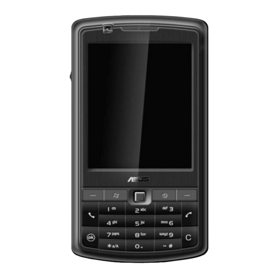
Page 7: Appearance
華 碩 電 腦 華 碩 電 腦 GTC ■ Service Manual 3. Appearance 3.1 Front View ASUS Proprietary... -
Page 8: Side View
華 碩 電 腦 華 碩 電 腦 GTC ■ Service Manual 3.2 Side View ASUS Proprietary... -
Page 9: Pcb Placement
華 碩 電 腦 華 碩 電 腦 GTC ■ Service Manual 4. PCB Placement 4.1 Main Board Top View WIFI Logic PWR_EN Block BAT_FAULT# MODE VBAT SYS_EN V_BKBT 4.2 Main Board Bottom View con3 con1 U600 ASUS Proprietary... -
Page 10: Equipment List
華 碩 電 腦 華 碩 電 腦 GTC ■ Service Manual 5. Equipment List 5.1 Ha rdware Power source: pow er supply (Monitor current) igital Phosphor Oscillo scope igital Meter ASUS Proprietary... - Page 11 華 碩 電 腦 華 碩 電 腦 GTC ■ Service Manual Mechanical Auxiliary Tool & tooling ‧ Screwdriver ( T5 * Cross + ) ‧ Tweezers ‧ Plastic Wrench Micro SD ASUS Proprietary...
-
Page 12: Trouble Shooting Case
“Power-On Sequence” issues. First, we can check the Current of the device during the OS booting process then try to measure the “Power ON Sequence”. In P750 design concept; The System will auto Power On in two conditions One is first connect to device, another the voltage drop below 2.8V... -
Page 13: Cpu Bga
6.1.3 NAND Flash In Item 2, if the d ata can’t response from TP28 ( SD15 ), in my opinion is try to re-flash the data to NAND flash via JTAG. Figure 1. PMU ASUS Propriet... -
Page 14: Mmi Test Item
CON1, the main of the reason should be CPU NG. F. V_LED If the backlight can not active on the LCD panel, w e should measure the 12V on the “V_LED”. If not then check the relate components o the U48. ASUS Proprietary... -
Page 15: Vibrator Test
We can measure the 32.768 for X2 clock signal. We can try to replace the CPU and X2 on this item failure. 6.2.4 Storage Test It should be U6 (Flash m emory) on soldering issue or com ponent defective. ASUS Proprietary... -
Page 16: Micro Sd Test
CPLD which will cause the RGB LED always illuminated red light. Please replace the CPLD o n PCB. If one of the colors can’t works on RGB LED, please check the soldering issue on R621, R622, R623 or replace the LED6 ASUS Proprietary... - Page 17 電 腦 華 碩 電 腦 GTC ■ Service Manual Figure 5. Indication LED Circuit B. Keypad LED failure Please measure the U88.4 (KEY_LED_EN) ->2.9V,if the result is true please check the U88. Figure 6. Keypad LED power ASUS Proprietary...
-
Page 18: Camera Test & Vga Camera
The CPLD control signal a. 3M: SENSOR_2M_PD = 0V, SENSOR_2M_RST# = 2.9V, SENSOR_2M_CLKEN = 2.9V b. VGA: SENSOR_VGA_PD = 0V, SENSOR_VGA_RST# = 2.9V, SENSOR_VGA_CLKEN = 2.9V If the signal is abnormal please try to change U600 ( CPLD). ASUS Proprietary... - Page 19 華 碩 電 腦 華 碩 電 腦 GTC ■ Service Manual Figure 8. Camera control signal ASUS Proprietary...
-
Page 20: Check Sim
Check the SIM connector Pin soldering status. SIM_VCC_R 1.8/3.3V ( general is 3.3V ) II. SIM_RST 0V ( Read mode ), III. SIM_CLK_R clock (Read mode) IV. SIM_DAT_R high-low transition (Read mode) Figure 10. SIM card connector circuit ASUS Proprietary... -
Page 21: Battery Test
Figure 11. Charger IC circuit Can’t read the battery ID Check the HDQ_TXD#_PLD and HDQ_RXD_PLD signal. The signal will be detect for a period on the correct status. If the can’t detect then should re-place the U600 (CPLD) NG. ASUS Proprietary... -
Page 22: Sdram Test
6.2.10 SDRAM Test If we can execute the MMI tool,SDRAM should be normal. If the result is fail, please also check the U7/U8 relative the signal. C. nSDCS0 D. nSDCAS, nSDRAS E. SDCKE1 F. SA12, SD15 Figure 13. SDRAM circuit ASUS Proprietary... - Page 23 First check the voice signal on MIC_HEADSET_R. If didn’t work please check the component (R55, R57, C120, C112, C123). F. Can’t Exit the headset mode Please check HP_DET ->0V,If the answer is not please refer to item A. ASUS Proprietary...
- Page 24 Figure 15. Class D Amp for speaker B. On-Board Microphone can’t Record If the quality is poor please change the U11. If the function total un-work please check the (L1, C121, C124, C125, 126). Figure 16. Microphone circuit ASUS Proprietary...
-
Page 25: Turn On/Off Radio
Modem Power G. CCPU_VCC-> 3.6V. if not please check the U75 (Step-Down Converter). Figure 18. Step-down converter for modem power H. Check below item VDD_1V5 1.5V VDD_1V8 1.8V VDD_2V75 2.75V VDD_2V85 2.85V ASUS Proprietary... - Page 26 Modem to System Interface The main of the purpose is level shift on CPLD between Modem and System. We can check the component (R711 ~ R715, R763 ~ R766), If the result is normal then try to change the U600 (CPLD). ASUS Proprietary...
-
Page 27: Version Check
A. Board level test The specify key include(joy dial up, joy dial down, joy dial action, 4, 8, clear, #) The P750’s keypad matrix contain for (row * 6, column*5). At least we need 6 buttons to fully cover each trace, it is weak for joy dial on 3 XYZ direction test. - Page 28 Keypad IC for itself. If the “interrupt#” and “watchdog reset#” are0~2.6V, it always cause abnormal on U90. We can try to re-heat the chip U90 or replace it. Figure 21. Keypad driver circuit Figure 22. Keypad matrix ASUS Proprietary...
-
Page 29: Wifi Board-Level Test
The power of the chip is well. We still can’t get the signal from GPS_TX, GPS_RX. Please check the R1011 -> 47K ohm? If the answer is true then try to change the U600. 6.2.17 PS Board-Level Test Follow the test item 16. Figure 23. GPS power ASUS Proprietary... -
Page 30: Tmc Test
(U20). If the result is NG please check the below item. BT_VCC_3.3V R104, R111 USB signal R102, R104, R110, R111, R112 USB protocol check If all of item is pass , please re-work the chip U20. Figure 24. BT connection ASUS Proprietary... -
Page 31: Power Consumption
CPU. After remove the resistor R217 we can use the power meter to measure the current on the circuit. The reference value is below 10mA. If over the value we can try to change the CPU to extend the idle time. Figu re 25. VCC core source ASUS Proprietary... -
Page 32: Camera Short
U951 NG. The U951 is response DC/DC converter to Modem power amplify. Try to remove the R951 and detect the system’s power current from the power supply. If the answer is true please replace the U951. Figure 26. DC/DC converter for wideband PA ASUS Proprietary... -
Page 33: Rf Layout Placement
華 碩 電 腦 華 碩 電 腦 GTC ■ Service Manual 8. RF Layout placement ASUS Proprietary... -
Page 34: Rf Block Diagram
華 碩 電 腦 華 碩 電 腦 GTC ■ Service Manual 9. RF Block Diagram RF FEM Signal True table The value “1” means level High , “0” means Level Low. ASUS Proprietary... - Page 35 華 碩 電 腦 華 碩 電 腦 GTC ■ Service Manual E-GSM 900 Power (PL5) ASUS Proprietary...
-
Page 36: Transmit Mode
華 碩 電 腦 華 碩 電 腦 GTC ■ Service Manual 850/EGSM: PL5 1.29(V) ;PL19 0.27(V) PL0 1.28(V) ;PL 15 1800/1900: 9.1 Transmit Mode ASUS Proprietary... - Page 37 3. BPF900 : SAW FILTER BG :850MH RX path 4. BPF901 : SAW FILTER TA : 900MH TX 900/850path 5. BPF902 : SAW FILTER LF : 1800MH TX 1800/1900path 6. BPF902 : SAW FILTER SW : 1900MH 7. OSC900: 26MHz Crystal NDK/W-168-281 ASUS Proprietary...
- Page 38 華 碩 電 腦 華 碩 電 腦 GTC ■ Service Manual : : 1:C902 2:C903 3:C906 U900 4:C931 OSC900 U901 5:R983 6:R927 OSC 900: 26MHz Tx Mode ASUS Proprietary...
- Page 39 華 碩 電 腦 華 碩 電 腦 GTC ■ Service Manual --TX U900 U901 1:C92 ASUS Proprietary...
-
Page 40: Wcdma
To Antenna Antenna WRX-IQ WTX-IQ TX path RX path WCDMA TX / RX path 1. U901: GSM Power Amplifier SKY77513 2. U950: WCDMA Transceiver RF3100 3. U953: WCDMA Power Amplifier SKY77174 4. U955: COUPLER LDC181G9519B-327 5. U954: ISOLATOR CES201G95DCB000 ASUS Proprietary... - Page 41 華 碩 電 腦 華 碩 電 腦 GTC ■ Service Manual 6. U956: SAW Duplexer MURATA1G95AA0B00R057 7. U952: POWER DETECTOR LMV221SD 8. U951: DC CONVERTER LM3208TL 9. OSC900: 26MHz Crystal NDK/W-168-281 DB3150 DB3150 DB3150 ASUS Proprietary...
-
Page 42: Wcdma Tx Path
The output power passes through coupler (U955), isolator (U954), duplexer (U956), to the T/R switch (U901) on the FEM (SKY77513). Finally the power will radiated via matting circuit and connector (Con900). WCDMA TX Schematic path ASUS Proprietary... -
Page 43: Tx Measurement
0x1C8 0x1AA 21.32 0x31E 0x340 0x3FF 0x1B3 0x168 20.7 0x30A 0x33D 0x3FF 0x19E 0x147 19.31 0x2F4 0x33B 0x3FF 0x188 0x127 18.33 0x2DD 0x336 0x3FF 0x173 0x116 17.25 0x2C6 0x331 0x3FF 0x15E 0x106 11.74 0x2B0 0x32E 0x3FF 0x148 0xF5 ASUS Proprietary... - Page 44 0xCC 0x243 0x3FF 0xC8 0xE5 -24.28 0xAE 0x1ED 0x3FF 0xC8 0xE5 -34.1 0xAB 0x19B 0x3FF 0xC8 0xE5 -40.54 0xAA 0x14D 0x3FF 0xC8 0xE5 -42.34 0xAA 0xFF 0x3FF 0xC8 0xE5 -42.32 0xAA 0xAD 0x3FF 0xC8 0xE5 9.67 0x285 1023 ASUS Proprietary...
-
Page 45: Test Procedure
Spectrum Setting: Freq=1950MHz. Caution: Must add the attenuator/DC Blocking or series connection 100PF Cap on the end of the Cable. It will avoid the direct current damage the spectrum authentically. The Power values all are relativity not absolute. R968.1 ASUS Proprietary... - Page 46 華 碩 電 腦 華 碩 電 腦 GTC ■ Service Manual C975.1 ASUS Proprietary...
- Page 47 華 碩 電 腦 華 碩 電 腦 GTC ■ Service Manual WCDMA TX Path_Power Sensor_pin6 U954.6 ASUS Proprietary...
- Page 48 華 碩 電 腦 華 碩 電 腦 GTC ■ Service Manual WCDMA TX Path Isolator Output_L901 L901 ASUS Proprietary...
- Page 49 華 碩 電 腦 華 碩 電 腦 GTC ■ Service Manual WCDMA TX Path Duplexer Output_R979 ASUS Proprietary...
- Page 50 華 碩 電 腦 華 碩 電 腦 GTC ■ Service Manual WCDMA TX Path RF Connector ASUS Proprietary...
-
Page 51: Wcdma Rx
WCDMA TRANSMITTER IC RF3100(U950) PIN X1_A ,MX1_B again. After down converting the signal’s frequen cy and transforming into IQ signals, the IQ signals (WRX_I_P, WRX_ I_N, WRX_Q_P, WRX_Q_NMAX2391) travel to Base Band IC DB3150 (U701). WCDMA RX Path Schematic_1 ASUS Proprietary... - Page 52 華 碩 電 腦 華 碩 電 腦 GTC ■ Service Manual MA RX Path Schemat ic_2 ASUS Proprietary...
-
Page 53: Wcdma Rx Path Measurement
B. Launch the P_E_Tool. Click the CDMA TX mode. C. Choose Com Port D. Choose Band I (Pegasus Pro Only Band I ) E. Choose WCDMA RX F. Setting the WCDMA RX channel, please set the Agilent 8960 to CW mode .The power: -30 ~ -40dBm ASUS Proprietary... -
Page 54: Rx Test Procedure
Setting: Fre q=2140MHz. Caution: Must add the attenuator/DC Blocking or series connection 100PF Cap on the end of the Cable. It will avoid dire t current damage the spectrum authentically. The Power values all are relativity not absolute. R983.2 ASUS Proprietary... - Page 55 華 碩 電 腦 華 碩 電 腦 GTC ■ Service Manual WCDMA RX Path LNA Output_U950 pin29 ASUS Proprietary...
- Page 56 華 碩 電 腦 華 碩 電 腦 GTC ■ Service Manual WCDMA RX Path Mixer Input_B ASUS Proprietary...
- Page 57 華 碩 電 腦 華 碩 電 腦 GTC ■ Service Manual WCDMA TX Path I, Q ASUS Pr oprietary...
- Page 58 華 碩 電 腦 華 碩 電 腦 GTC ■ Service Manual ASUS Proprietary...
- Page 59 華 碩 電 腦 華 碩 電 腦 GTC ■ Service Manual WCDMA RF3100 3 Wire Bus ASUS Proprietary...
-
Page 60: Wcdma Pa Power Control
RF_DAC1 and RF_DAC2 used to the Power level control by (PA and DC/DC converter). WPOW DET EN Power WPOW_DET DC/DC WDCDC_EN Couple WCDMA From RF3100 TX Output WB+EGG Digital BB CTRL_DATA WCDMA CTRL_StrB Controller Transceiver CTRL_Clock DB 3150 WBCLK ASUS Proprietary... - Page 61 華 碩 電 腦 華 碩 電 腦 GTC ■ Service Manual ASUS Proprietary...
- Page 62 专注于微波、射频、天线设计人才的培养 易迪拓培训 网址:http://www.edatop.com 射 频 和 天 线 设 计 培 训 课 程 推 荐 易迪拓培训(www.edatop.com)由数名来自于研发第一线的资深工程师发起成立,致力并专注于微 波、射频、天线设计研发人才的培养;我们于 2006 年整合合并微波 EDA 网(www.mweda.com),现 已发展成为国内最大的微波射频和天线设计人才培养基地,成功推出多套微波射频以及天线设计经典 培训课程和 ADS、HFSS 等专业软件使用培训课程,广受客户好评;并先后与人民邮电出版社、电子 工业出版社合作出版了多本专业图书,帮助数万名工程师提升了专业技术能力。客户遍布中兴通讯、 研通高频、埃威航电、国人通信等多家国内知名公司,以及台湾工业技术研究院、永业科技、全一电 子等多家台湾地区企业。 易迪拓培训课程列表:http://www.edatop.com/peixun/rfe/129.html 射频工程师养成培训课程套装 该套装精选了射频专业基础培训课程、 射频仿真设计培训课程和射频电 路测量培训课程三个类别共 30 门视频培训课程和 3 本图书教材;旨在 引领学员全面学习一个射频工程师需要熟悉、 理解和掌握的专业知识和 研发设计能力。通过套装的学习,能够让学员完全达到和胜任一个合格...
- Page 63 专注于微波、射频、天线设计人才的培养 易迪拓培训 网址:http://www.edatop.com CST 学习培训课程套装 该培训套装由易迪拓培训联合微波 EDA 网共同推出,是最全面、系统、 专业的 CST 微波工作室培训课程套装, 所有课程都由经验丰富的专家授 课,视频教学,可以帮助您从零开始,全面系统地学习 CST 微波工作的 各项功能及其在微波射频、天线设计等领域的设计应用。且购买该套装, 还可超值赠送 3 个月免费学习答疑… 课程网址:http://www.edatop.com/peixun/cst/24.html HFSS 天线设计培训课程套装 套装包含 6 门视频课程和 1 本图书,课程从基础讲起,内容由浅入深, 理论介绍和实际操作讲解相结合,全面系统的讲解了 HFSS 天线设计的 全过程。是国内最全面、最专业的 HFSS 天线设计课程,可以帮助您快 速学习掌握如何使用 HFSS 设计天线,让天线设计不再难… 课程网址:http://www.edatop.com/peixun/hfss/122.html 13.56MHz NFC/RFID 线圈天线设计培训课程套装 套装包含...