Advertisement
Quick Links
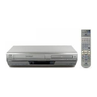
SERVICE MANUAL
DVD PLAYER & VIDEO CASSETTE RECORDER
2003
11
YD002
HR-XV3EK, HR-XV31EK,
HR-XV32EK, HR-XV3EX,
HR-XV31EX, HR-XVS30EK,
HR-XV3EK, HR-XV31EK, HR-XV32EK, HR-XV3EX, HR-XV31EX, HR-XVS30EK, HR-XVS30EX [D3PV1,D3PS1]
1
PRECAUTION. . . . . . . . . . . . . . . . . . . . . . . . . . . . . . . . . . . . . . . . . . . . . . . . . . . . . . . . . . . . . . . . . . . . . . . . . 1-3
2
SPECIFIC SERVICE INSTRUCTIONS . . . . . . . . . . . . . . . . . . . . . . . . . . . . . . . . . . . . . . . . . . . . . . . . . . . . . . 1-8
3
DISASSEMBLY . . . . . . . . . . . . . . . . . . . . . . . . . . . . . . . . . . . . . . . . . . . . . . . . . . . . . . . . . . . . . . . . . . . . . . 1-11
4
ADJUSTMENT . . . . . . . . . . . . . . . . . . . . . . . . . . . . . . . . . . . . . . . . . . . . . . . . . . . . . . . . . . . . . . . . . . . . . . . 1-17
5
TROUBLESHOOTING . . . . . . . . . . . . . . . . . . . . . . . . . . . . . . . . . . . . . . . . . . . . . . . . . . . . . . . . . . . . . . . . . 1-26
COPYRIGHT © 2003 VICTOR COMPANY OF JAPAN, LIMITED
HR-XVS30EX
TABLE OF CONTENTS
(EK models)
(VHS models)
(EX models)
(S-VHS models)
(S-VHS models)
No.YD002
2003/11
Advertisement

Related Manuals for JVC HR-XV3EK


Summary of Contents for JVC HR-XV3EK
- Page 1 (S-VHS models) (S-VHS models) HR-XV3EK, HR-XV31EK, HR-XV32EK, HR-XV3EX, HR-XV31EX, HR-XVS30EK, HR-XVS30EX [D3PV1,D3PS1] TABLE OF CONTENTS PRECAUTION............... . . 1-3 SPECIFIC SERVICE INSTRUCTIONS .
- Page 2 SPECIFICATION HR-XV3EK, HR-XV31EK, HR-XV3EX, HR-XV31EX HR-XVS30EK HR-XVS30EX HR-XV32EK GENERAL Power requirement AC 220V - 240V, 50 Hz/60 Hz Power consumption Power on 26 W 30 W Power off 6.0 W Temperature Operating 5°C to 40°C Storage -20°C to 60°C Operating position Horizontal only 435 mm ×...
-
Page 3: Precaution
Precautions for Service 1.4.1 Handling of Traverse Unit and Laser Pickup (1) Do not touch any peripheral element of the pickup or the actuator. (2) The traverse unit and the pickup are precision devices and therefore must not be subjected to strong shock. (3) Do not use a tester to examine the laser diode. -
Page 4: Specific Service Instructions
SECTION 2 SPECIFIC SERVICE INSTRUCTIONS Different table of feature The following table indicates main different points between models HR-XV3EK, HR-XV31EK,HR-XV32EK, HR-XV3EX, HR-XV31EX, HR-XVS30EK, and HR-XVS30EX. HR-XV3EK HR-XV31EK HR-XV32EK HR-XV3EX HR-XV31EX HR-XVS30EK HR-XVS30EX ← ← ← POWER PLUG 3PIN 3PIN ←... - Page 5 2.2 Service position This unit has been designed so that the Mechanism and Main board assemblies can be removed together from the bottom Main board assembly Regulator board assembly chassis. Before diagnosing or servicing the circuit boards, take out the major parts from the bottom chassis. TP111 D.FF 2.2.1 How to set the "Service position"...
- Page 6 2.3.2 Setting the User RCU mode 2.5.2 Lubrication (1) Turn off the power. With no need for periodical lubrication, you have only to lubricate (2) Press the "REC" and "PAUSE" buttons of the VCR simul- new parts after replacement. If any oil or grease on contact parts taneously.
-
Page 7: Disassembly
SECTION 3 DISASSEMBLY Removing the major parts 3.1.1 Destination of connectors 3.1.3 Disassembly procedure Two kinds of double-arrows in connection tables respectively Step/ Fig. Point Note Part Name show kinds of connector/wires. Loc No. : Flat wire : Wire : Board to board (B-B) Top cover 3-1d 6(S1a) - Page 8 <Note 3c> • When reattaching the Drum assembly, secure the screws (S3c to S3e) in the order of c, d, e. (S3c) (S3e) (S3d) (S3e) Mechanism (S3d) assembly Drum HOOK assembly (S3c) <Note 3c> <NOTE> Attach the Drum assembly appropriately, since the installation state of the Drum assembly influences the FM WAVEFORM LINEARITY greatly.
- Page 9 HOLD PART OF ROLLER ARM ASS'Y (L3a) WHILE ATTACHING INERTIA PLATE. INERTIA PLATE SHOULD BE ATTACHED SO AS TO SER SMALL DIAMETER OF CENTRAL ROUND HOLE ABOVE. POSITION ROLLER'S INSTALLATION HOLE IN THE "A" PART. (P3a)"c" INSERT ROLLER UNTIL THE "b" (L3b)"b"...
- Page 10 Loading mechanism assembly 3.2.1 Removing the tray (See Figure 3-2a, Figure 3-2b, Figure 3-2c, Figure 3-2d, Figure 3-2e, Figure 3-2f) (1) Push a of the slide cam on the hole in the right side of the Tray loading base by using a driver until it stops. (See Figure 3- 2a.) (2) The tray comes out.
- Page 11 3.2.2 Removing the traverse mechanism assembly (See Figure 3-2g) Reverse the loading mechanism assembly. Remove the four Loading mechanism assembly screws B attaching the traverse mechanism assembly. Remove the traverse mechanism assembly upward. Traverse mechanism assembly Fig.3-2g 3.2.3 Removing the elevator (See Figure 3-2h and Figure 3-2j) •...
- Page 12 3.2.4 Removing the loading motor (See Figure 3-2k and Figure 3-2l) • Prior to the following procedure, remove the tray, the traverse Loading base Belt mechanism assembly, and the elevator. (1) Remove the belt from the pulley. Pulley Slide cam Pulley (2) Remove two screws C attaching the loading motor.
-
Page 13: Adjustment
SECTION 4 ADJUSTMENT Before adjustment 4.1.4 Color (colour) bar signal,Color (colour) bar pattern 4.1.1 Precaution Colour bar signal [PAL] Colour bar pattern [PAL] • The adjustments of this unit include the mechanism com- White(100%) (75%) patibility and electrical adjustments. During the perfor- White(75%) mance of this work, be sure to observe the precautions for each type of adjustment. - Page 14 4.1.7 EVR Adjustment 4.2 Mechanism compatibility adjustment [VHS SECTION] Some of the electrical adjustments require the adjustment per- Notes: formed by the EVR system. The main unit have EEPROMs for • Although compatibility adjustment is very important, it storing the EVR adjustment data and user setups. is not necessary to perform this as part of the normal Notes: servicing work.
- Page 15 4.2.2 FM waveform linearity Proper waveform variation Signal (A1) • Alignment tape(SP, stairstep, PAL) [MHPE] (A2) • Alignment tape(LP, stairstep, PAL) [MHPE-L] Mode • PB Equipment • Oscilloscope Measuring point (D) • TP106 (PB. FM) External trigger (E) • TP111 (D.FF) Improper waveform variation Down Adjustment part (F)
- Page 16 4.2.4 A/C head phase (X-value) 4.3 Electrical adjustment [VHS SECTION] Signal (A1) • Alignment tape(SP, stairstep, PAL) [MHPE] Note: (A2) • Alignment tape(LP,stairstep,PAL) [MHPE-L] The following adjustment procedures are not only necessary Mode • PB after replacement of consumable mechanical parts or board Equipment •...
- Page 17 (1) Record the signal (A2) in the mode (B1), and play back 4.3.3 Syscon circuit the recorded signal. Notes: (2) Set the VCR to the manual tracking mode. • When perform this adjustment, remove the Mechanism (3) Set the VCR to the FWD slow (+1/6x) mode. assembly.
- Page 18 Electrical adjustment (DVD SECTION) 4.4.1 Test mode setting method (1) Press POWER button then press VCR/DVD repeatedly so that the DVD indicatorlights up. (2) Press the POWER button again to set the stand-by mode. (3) Transmit the code "FA" from the Jig RCU. (4) The FDP shows the test mode content in the form of "∗...
- Page 19 4.4.5 Optimization adjustment of Front End parameter Adjustment to optimize Front End parameter must be performed in each mechanism assembly of this model for high-speed start- ing.Please perform optimization according to the following procedures just after all-initialization is completed and when FL display shows anything except "∗0"...
- Page 20 4.4.7 Flap adjustment of the pick-up guide shaft Please perform flap adjustment of the pick-up guide shaft in the following case: • Just after you exchange the pick-up. • Just after you exchange the spindle motor. • Just after you exchange the traverse mechanism base. NOTE: Please perform flap adjustment of the pick-up guide shaft when you exchange the parts above and also when you remove the parts above.
- Page 21 4.4.7.2 Preparation for adjustment (1) Remove the DVD unit.(Refer to the SECTION 3 Removing the major parts) (2) Connect a extention cord between CN502 of DVD servo control board assembly and CN7301 of Main board assembly. (See Fig.4-4a) (3) Connect a extention cord between CN501 of DVD servo control board assembly and CN5302...
-
Page 22: Troubleshooting
SECTION 5 TROUBLESHOOTING Manually removing the cassette tape (3) Unload the pole base assembly by manually turning the gear of the loading motor until the pole base assembly is If you cannot remove the cassette tape which is loaded because hidden behind the cassette lid. - Page 23 5.3 Emergency display function (VHS SECTION) EMG display of FDP display mode (1) Transmit the code “59” from the Jig RCU. This unit saves details of the last two emergencies as the EMG The FDP shows the EMG content in the form of “E:**:**”. history and allows the status of the VCR and the mechanism of each emergency to be shown both on the display and as OSD in- <Example 1>...
- Page 24 Encoder data : Sensor information (See sensor information details.) GG : Capstan motor speed (See Mechanism mode sequence.) HH : Key code (JVC code) Remote pause : Supply reel winding diameter data higher 8 bits. End sensor : Supply reel winding diameter data lower 8 bits.
- Page 25 5.3.4 EMG content description Note: EMG contents “E08/E09” are for the model with Dynamic Drum (DD). CONTENT CAUSE E01: Loading EMG If the mechanism mode does not change to the next mode within 4 sec- 1. The mechanism is locked in the middle of the mode transition during a tape loading operation. onds after the loading motor starts rotating in the loading direction, while 2.
- Page 26 5.3.5 EMG detail information <1> *2 : Mechanism operation mode The status (electrical operation mode) of the VCR and the status [Table of MN*] (mechanism operation mode/sensor information) of the mecha- Display Mechanism operation mode nism in the latest EMG can be confirmed based on the figure in Command standby (No command to be executed) EMG detail information <1>...
- Page 27 3- : Mechanism sensor information *5 : Cassette tape type <1> [Common table of MN* and HD*] Display Cassette tape type <1> Cassette type not identified Mechanism sensor informatio n Large reel/small reel (T-0 to T-15/T-130 to T-210) not classified Display Mechansim Small reel, thick tape (T-120) identified/thin tape (T-140) identified...
- Page 28 Troubleshooting (DVD SECTION) Press OPEN /CLOSE key Is tray Confirmation of tray drive circuit operation and circuit in surrounding correct? Is the traverse moving See "5.5.3 Traverse movement error" along the innermost in "Check points for individual errors" perimeter for SW detection? "NO DISC"...
- Page 29 Check points for each error (DVD SECTION) 5.5.1 Spindle start error (1) Defective spindle motor • Are there several ohms resistance between each pin of CN201 "1-2","2-3","1-3"? (The power supply is turned off and measured.) • Is the sign wave of about 100mVp-p in the voltage had from each terminal? [ CN201"10"(H1+),"11"(H1-),"7"(H2+),"8"(H2-),"5"(H3+),"6"(H3-) ] (2) Defective spindle motor driver (IC251) •...
- Page 30 5.5.6 Spindle CLV NG • IC101 -- "30"(ARF-), "31(ARF+). • Does not the input or the output of driver's spindle signal do the grip? • Has the tracking been turned on? • Spindle motor and driver is defective. • Additionally, "IC101 and IC301"...
- Page 31 BOARD INTERCONNECTIONS Page 2-5 Page 2-23 REGULATOR Page VIDEO/AUDIO Page Page 2-27 S-SUB Page Page 2-11 Page 2-21 SYSCON Page 2-13 TUNER Page 2-15 TERMINAL Page 2-17 ON SCREEN Page 2-19 NOT USED Page 2-25 Page 2-26 p10551001a_rev0...
- Page 32 DC[+] F5001 C5002 0.022 DC[-] DC[-] DC[-] /250 /250 T5001 L5204 QQS0218-001 SHORT -28V -28V -28V QQS0219-001 Q5301 2SD2144S/UV/ 2SC3576-JVC D5203 ERA18-02 C5212 DC[+] 1SR153-400 TO SYSCON C5001 SW12V SW12V Q5302 10ERB20 R5303 0.068 DTA114EKA C5006 PG104RS Q5303 /250 SW5V...
- Page 33 MAIN ( VIDEO/N.AUDIO ) SCHEMATIC DIAGRAM OPEN SECAM_REC_COLOR PB_FM EE[L] OPEN SHORT TO SYSCON MESECAM_DET 2.2k CTL2 2.2k CTL1 VIDEO_ENV 0.01 0.01 D.FF A.MUTE[H] TP111 D.FF I2C_DATA_AV I2C_CLK_AV TO FMA OPEN OPEN OPEN OPEN OPEN 0‘ NA_PB OPEN TP106 OPEN NA_REC PB.FM OPEN...
- Page 34 MAIN ( S-SUB ) SCHEMATIC DIAGRAMS [HR-XVS30EK, HR-XVS30EX] TO VIDEO/N.AUDIO CN511 SW12V SW5V KILLER_DET SW5V VHS[H] TO_PS_C V_FROM_AV Y_TO_SUB FROM_PS_C SYNC_OUT REC_COLOR TO_PS_Y FROM_SUB_EMPH Y_TO_AV FROM_PS_Y SW12V TO_SUB_EMPH SW12V V_TO_OSD NOT USED L501 100^ C539 0.01 C519 270p_2% C525 C524 C523 C522 C521...
- Page 35 MAIN ( FMA ) SCHEMATIC DIAGRAM R2254 R2256 2.2k Q2253 VR2251 DTC144WKA REC_FM_ADJ Q2252 Q2251 DTC144WKA DTC144WKA Q2254 DTC114EKA C2222 0.01 TO REG AL5.8V SW5V SW12V TP2253 TO TUNER RF_AUDIO Q2202 DEMOD[R] DTC144WKA DEMOD[L] C2208 0.015 Q2201 R2253 DTA144WKA TO SYSCON R2220 R2257 OPEN...
- Page 36 MAIN ( SYSCON ) SCHEMATIC DIAGRAM TO VIDEO/N.AUDIO SEP[H] N.REC_ST[H] N.REC[H] I2C_DATA_AV I2C_CLK_AV A.MUTE[H] MESECAM_DET SECAM[H] CTL1 CTL2 D.FF C.SYNC V.PULSE D4001 SHORT CTL[+] CTL[-] EE[L] S_DET SECAM_DET C3039 VIDEO_ENV OPEN SB_GAIN C3038 OPEN TO FMA ET_REC[H] TO CAPSTAN MDA I2C_CLK_AV CN3001 I2C_DATA_AV...
- Page 37 MAIN ( TUNER ) SCHEMATIC DIAGRAM TU6001 TO REG L6002 RF5V SW5V L6005 SW12V L6004 L6003 L6701 3.3^ C6751 C6752 /6.3 0.01 TO FMA DEMOD[L] TO VIDEO/N.AUDIO DEMOD[R] TO FMA TO VIDEO/N.AUDIO TU_AUDIO K6706 RF_AUDIO TO FMA C6718 0.01 C6715 C6717 R6716 R6714...
- Page 38 MAIN ( TERMINAL ) SCHEMATIC DIAGRAM MAIN(TERMINAL) TO SW JACK CN7191 TO VIDEO/AUDIO CN7104 IF_SEL_YV_IN F.AUDIO[L] TU_VIDEO FRONT_V_IN F.AUDIO[R] B7101 R7119 IC7102 MM1503 IC7301 OPEN LA7151 FRONT_V_IN TO TUNER RF_VIDEO L7101 µ R7121 FRONT_Y_IN TO FMA R7120 DEC_OUT[L] FRONT_C_IN DEC_OUT[R] A.IN1[L] A.IN1[R] A.IN2[L]...
- Page 39 MAIN ( ON SCREEN ) SCHEMATIC DIAGRAM R225 3.3k B206 TO REG R223 R224 Q207 OPEN 2SA1037AK/QR/ L206 2SA1530A/QR/ R216 R213 0‘ R212 Q208 C222 L204 L201 OPEN C209 0.47 TO VIDEO/N.AUDIO R220 OPEN C218 C217 V_TO_OSD V_FROM_OSD 2Fsc CHARA_DATA C201 C202 R211 C214 C215...
- Page 40 2D DIGITAL SCHEMATIC DIAGRAMS [HR-XVS30EK, HR-XVS30EX] C1212 0.001 C1211 /6.3 R1207 5.6k L1202 R1208 180‘ C1216 IC1201 JCP8036 JCP8057 C1215 /6.3 L1203 330^ IIC_DATA NC( TEST) IIC_CLK NC( TEST) RESET NC( TEST) C1237 CMUTE FSC_IN C1236 C1217 C1218 VREF NC( TEST) R1210 VR1201 R1211...
- Page 41 TERMINAL ( I/O ) SCHEMATIC DIAGRAM R7701 OPEN J7001 S_IN OPEN R919 1/4W R7702 OPEN Q907 L901 4.7^ R914 L906 4.7^ R927 R922 R902 Q902 R909 L902 4.7^ R915 Q908 L907 4.7^ R928 R7703 OPEN C902 C903 C918 C919 C904 C905 L903 C920...
- Page 42 DISPLAY AND SW JACK SCHEMATIC DIAGRAMS C7008 D7021 RD6.8ES/B1 MTZJ6.8A C7007 R7052 100k IC7003 R7053 100k SN74HCT08APW R7054 100k R7055 100k R7056 100k 100k R7057 100k R7058 R7059 100k R7060 100k R7061 100k R7062 100k R7063 100k QNN0591-001 QND0084-001 QNN0592-001 R7064 100k QND0085-001...
- Page 43 DVD SERVO CONTROL SCHEMATIC DIAGRAM C144 0.01/16 C113 C145 R114 R131 SGND C116 0.1/16 TESTSG C117 0.047/16 R116 C118 0.027/16 D1.8V D3.3V S3.3V TBAL R106 C119 560P C305 C307 C309 FBAL R107 IC101 R125 C110 220P RFENV AN8703FH-V R117 R124 C115 K101 NQR0007-002X...
- Page 44 DVD AV DECODER SCHEMATIC DIAGRAM TP533 TP532 TP531 TP530 D1.8V D3.3V TP912 TP529 C592 TP528 TP913 TP527 C593 K502 R505 R506 C521 K504 NQR0339-001X R507 R508 C524 C527 47/4 47/4 C591 C590 PWE0 C584 C585 C512 0.1/16 MD10 MD11 470p R584 C514 3.3K...
- Page 45 DVD FLASH ROM SCHEMATIC DIAGRAM C508 C502 D3.3V C503 C583 C505 MGND MGND AGND DGND DGND SGND C504 C509 IC509 K519 SST39VF160-7CEK NQR0339-001X C510 IC512 LADD16 LADD15 74LVC373APW-X INTP R523 R518 LADD14 LADD13 FLCS- R526 AD15 LADD19 LADD12 LADD6 CN504 AD19 LADD11 SSPIN0...
- Page 46 REGULATOR, JACK AND DISPLAY CIRCUIT BOARDS <01> REGULATOR <36> JACK LPB10206-001D DANGEROUS VOLTAGE LPB10206-001D D7004 D5209 K5102 C5212 C5311 C5310 C5207 D5310 L5301 D5203 D5204 D5101 R5104 CN5302 D5208 CP5301 B5305 D5217 L5204 C5307 C5102 D5213 L5302 C5308 C5204 D5211 D7191 L5303 C5312...
- Page 47 MAIN CIRCUIT BOARD <03> MAIN LPB10215-001B J7010 J7202 J7009 CN7103 CN7102 CN7101 C6014 B7103 C7508 L6002 C6054 Q7301 C6053 R7505 B7102 C542 R511 L6003 Q7303 L7501 R7507 C7504 C7301 C7302 C6013 Q501 C6052 R7504 C7304 C6055 L7502 B505 R512 R6050 R7324 C7506 C7305...
- Page 48 COMPONENT PARTS LOCATION GUIDE <MAIN> LPB10215-001B SWITCH AND DVD SERVO CONTROL CIRCUIT BOARDS REF.NO. LOCATION REF.NO. LOCATION REF.NO. LOCATION REF.NO. LOCATION REF.NO. LOCATION REF.NO. LOCATION REF.NO. LOCATION REF.NO. LOCATION REF.NO. LOCATION CAPACITOR C511 A D 10L C3043 B C 11C CN3001 A D 9J Q311...
- Page 49 TERMINAL AND 2D DIGITAL CIRCUIT BOARDS <06> TERMINAL LPB10216-001B R7706 R7731 R902 R961 C929 R930 C969 R959 Q901 C968 R7702 R7707 R7732 R929 C967 C955 R958 C928 L910 R922 Q903 C952 J7003 L920 R956 C920 R954 C921 R7701 J901 C919 C918 J7001 J7006...
- Page 50 VOLTAGE CHARTS <SW.REG> <MAIN> <2D DIGITAL> <TERMINAL I/O> <DVD> MODE MODE MODE MODE MODE MODE MODE MODE MODE MODE MODE MODE MODE MODE MODE MODE MODE MODE MODE MODE MODE PLAY PLAY PLAY PLAY PLAY PLAY PLAY PLAY PLAY PLAY PLAY PLAY PLAY...
- Page 51 VIDEO BLOCK DIAGRAM ( 1 ) IC501-3 IC501-5 WF10 IC501-12 WF11 IC501-14 WF12 IC501-16 WF13 IC501-18 WF14 IC501-36 WF15 IC501-40 WF16 IC501-42 WF17 IC501-43 WF18 IC501-47 WF18 IC501-47 WF19 IC501-49 WF20 IC501-54 REC/PB 0.66Vp-p REC/PB 0.6Vp-p REC/PB 1.7Vp-p REC/PB 1.45Vp-p REC/PB 2.3Vp-p REC/PB 2.3Vp-p REC 0.39Vp-p...
- Page 52 VIDEO BLOCK DIAGRAM ( 2 ) VHS(H) MAIN (VIDEO/N. AUDIO) V FROM AV TO SUB SYNC_OUT REC COLOR FMA/DEMOD Y TO AV TO_SUB_EMPH ON SCREEN FROM_SUB_EMPH USED USED 2Fsc FILTER I2C_DATA_AV I2C_CLK_AV 67 69 SYSCON IF_SEL_YV_IN C.SYNC PB COLOR TP111 FRONT_V_IN CONT X-TAL...
- Page 53 AUDIO BLOCK DIAGRAM SYSTEM CONTROL BLOCK DIAGRAM 2-47 2-48...
- Page 54 CPU PIN FUNCTION <SYSCON IC3001> PIN NO. LABEL IN/OUT FUNCTION PIN NO. LABEL IN/OUT FUNCTION CTL[+] CTL(+) SIGNAL S.CASS[H] S.CASS DETECT SVss REC_SAFETY REC SAFETY SWITCH DETECT (SW ON:L) CTL[-] IN/OUT CTL(-) SIGNAL SW1/CONV_CTL[H] TUNER SYSTEM MODE:H CTLBIAS CTL BIAS VOLTAGE SW2/CH_SW TUNER SYSTEM MODE:L/CHANNEL SWITCHING SIGNAL CTLFB...
- Page 55 REMOTE CONTROLLER SCHEMATIC DIAGRAM NOTE : 1. All parts shown in this schematic are ciritical for sefety. 2. This schematic is only for reference. Avoid replacing individual parts. Replace the entire unite only. ( LP21036-030A ) KEY No. KEY NAME POWER PROG/G CODE Normal/3x/5x/TOP MENU...
-
Page 56: Parts List
Parts identified by the symbol are critical for safety. Replace only with specified part numbers. BEWARE OF BOGUS PARTS Parts that do not meet specifications may cause trouble in regard to safety and performance. We recommend that genuine JVC parts be used. 1. EXPLODED VIEW 1.1 PACKING AND ACCESSORY ASSEMBLY <M1>... - Page 57 1.2 FINAL ASSEMBLY <M2> DVD SERVO CONTROL BOARD ASSY <99> TRAVERSE MECHANISM ASSY <M5> BACK SIDE Grease LOADING JVS-1003 MECHANISM ASSY <M6> MECHANISM ASSY <M4> DVD UNIT<M5>, <M6>,<98>,<99> TERMINAL BOARD ASSY<06> 2D DIGITAL BOARD ASSY<05> MAIN BOARD ASSY<03> REGULATOR BOARD ASSY <01> 501A 501B 501D...
- Page 58 CN2001 Wire lets the bottom of BRACKET(DVD) pass. CN5001 CN7191 FRONT PWB CN7003 FRONT PWB CN7004 A/C HEAD CN7104 CN3102 CN3103 right side DRAWING FROM DIRECTION DRAWING FROM DIRECTION After Assembling FRONT PANEL After Assembling FRONT PANEL CN3103 CN3102 JACK BOARD ASSY CN7191 DRAWING FROM DIRECTION Connect the FJ CONN...
- Page 59 1.3 MECHANISM ASSEMBLY <M4> Not used A/C HEAD BOARD ASSY <12> LOADING MOTOR BOARD ASSY <55> PMD0044A-C,PMD0047A-C Classification Part No. Symbol in drawing Grease KYODO-SH-JB NOTE:The section marked in AA and BB indicate lubrication and greasing areas. COSMO-HV56 3-4(No.YD002)
- Page 60 1.4 TRAVERSE MECHANISM ASSEMBLY <M5> Grease =JVG-31N =CFD-4007ZY2 =PG-641 =1401C < Back side > 63.3mm 0.1mm 10.5mm 0.1mm EXL-V10-11C (No.YD002)3-5...
- Page 61 1.5 LOADING MECHANISM ASSEMBLY <M6> Grease JVG-31N JVS-1003 Back side (All circumferences) SWITCH BOARD ASSY ELM-J2-2C 3-6(No.YD002)
- Page 62 MODEL MARK MODEL MARK HR-XV3EK HR-XV31EX HR-XV31EK HR-XVS30EK HR-XV32EK HR-XVS30EX HR-XV3EX 2. PARTS LIST FINAL ASSEMBLY <M2> PACKING AND ACCESSORY ASSEMBLY <M1> Symbol No. Part No. Part Name Description Local Symbol No. Part No. Part Name Description Local ...
- Page 63 MODEL MARK MODEL MARK HR-XV3EK HR-XV31EX HR-XV31EK HR-XVS30EK HR-XV32EK HR-XVS30EX HR-XV3EX Symbol No. Symbol No. Part No. Part Name Description Local Part No. Part Name Description Local PQ45160 INERTIA PLATE LP30969-002B BRAKE LEVER LE40900-003A INSULATOR (x4) LP30003-033B TENSION SPRING...
- Page 64 MODEL MARK MODEL MARK HR-XV3EK HR-XV31EX HR-XV31EK HR-XVS30EK HR-XV32EK HR-XVS30EX HR-XV3EX Symbol No. Symbol No. Part No. Part Name Description Local Part No. Part Name Description Local QAR0284-001 SPINDLE MOTOR D5205 or 10ERB20-T2 FR DIODE QYSPSPU1740Z TAP SCREW M1.7 x 4mm(x3)
- Page 65 IC8001 or RC4558D-X Q4001 DTC114EKA-X TRANSISTOR Q4001 or UN2211-X TRANSISTOR DTC144WKA-X DIGI TRANSISTOR Q5301 2SD2144S/UV/-T TRANSISTOR or UN221E-X TRANSTSTOR Q5301 or 2SC3576-JVC-T TRANSISTOR 2SC2412K/QRS/-X TRANSISTOR Q5302 DTA114EKA-X DIGI TRANSISTOR or 2SD601A/QRS/-X TRANSISTOR Q5302 or UN2111-X TRANSISTOR or 2SC3928A/QRS/-X TRANSISTOR Q5303...
- Page 66 Q5314 or 2SD2394/EF/ TRANSISTOR NCB31EK-103X C CAPACITOR 0.01uF 25V K Q5316 2SD2144S/UV/-T TRANSISTOR NCB31CK-104X C CAPACITOR 0.1uF 16V K A,B,C,D,E Q5316 or 2SC3576-JVC-T TRANSISTOR NCB31CK-104X C CAPACITOR 0.1uF 16V K Q6030 2SA1037AK/QR/-X TRANSISTOR NCB31CK-104X C CAPACITOR 0.1uF 16V K Q6030 or 2SB709A/QR/-X...
- Page 67 MODEL MARK MODEL MARK HR-XV3EK HR-XV31EX HR-XV31EK HR-XVS30EK HR-XV32EK HR-XVS30EX HR-XV3EX Symbol No. Symbol No. Part No. Part Name Description Local Part No. Part Name Description Local C519 NDC31HG-271X C CAPACITOR 270pF 50V G C3027 QEKJ1EM-106Z E CAPACITOR...
- Page 68 MODEL MARK MODEL MARK HR-XV3EK HR-XV31EX HR-XV31EK HR-XVS30EK HR-XV32EK HR-XVS30EX HR-XV3EX Symbol No. Symbol No. Part No. Part Name Description Local Part No. Part Name Description Local R208 NRSA63J-222X MG RESISTOR 2.2kΩ 1/16W J R2237 NRSA63J-681X MG RESISTOR 680Ω...
- Page 69 MODEL MARK MODEL MARK HR-XV3EK HR-XV31EX HR-XV31EK HR-XVS30EK HR-XV32EK HR-XVS30EX HR-XV3EX Symbol No. Symbol No. Part No. Part Name Description Local Part No. Part Name Description Local R3096 NRSA63J-0R0X MG RESISTOR 0Ω 1/16W J R6707 NRSA63J-330X MG RESISTOR 33Ω...
- Page 70 MODEL MARK MODEL MARK HR-XV3EK HR-XV31EX HR-XV31EK HR-XVS30EK HR-XV32EK HR-XVS30EX HR-XV3EX Symbol No. Symbol No. Part No. Part Name Description Local Part No. Part Name Description Local B3304 NRSA63J-0R0X MG RESISTOR 0Ω 1/16W J NRSA63J-0R0X MG RESISTOR 0Ω 1/16W J...
- Page 71 MODEL MARK MODEL MARK HR-XV3EK HR-XV31EX HR-XV31EK HR-XVS30EK HR-XV32EK HR-XVS30EX HR-XV3EX Symbol No. Symbol No. Part No. Part Name Description Local Part No. Part Name Description Local C1218 NCF21EZ-104X C CAPACITOR 0.1uF 25V Z Q908 or 2SB709A/QR/-X TRANSISTOR...
- Page 72 MODEL MARK MODEL MARK HR-XV3EK HR-XV31EX HR-XV31EK HR-XVS30EK HR-XV32EK HR-XVS30EX HR-XV3EX Symbol No. Symbol No. Part No. Part Name Description Local Part No. Part Name Description Local C966 QEKJ0JM-476Z E CAPACITOR 47uF 6.3V M L918 QQL29BJ-100Z P COIL...
- Page 73 MODEL MARK MODEL MARK HR-XV3EK HR-XV31EX HR-XV31EK HR-XVS30EK HR-XV32EK HR-XVS30EX HR-XV3EX Symbol No. Symbol No. Part No. Part Name Description Local Part No. Part Name Description Local R7005 QRE141J-103Y C RESISTOR 10kΩ 1/4W J X7001 QAX0246-001Z C RESONATOR 8.00MHz...
- Page 74 MODEL MARK MODEL MARK HR-XV3EK HR-XV31EX HR-XV31EK HR-XVS30EK HR-XV32EK HR-XVS30EX HR-XV3EX Symbol No. Symbol No. Part No. Part Name Description Local Part No. Part Name Description Local IC501 or NDV8611VWA C264 NCB31CK-103X C CAPACITOR 0.01uF 16V K IC505...
- Page 75 MODEL MARK MODEL MARK HR-XV3EK HR-XV31EX HR-XV31EK HR-XVS30EK HR-XV32EK HR-XVS30EX HR-XV3EX Symbol No. Symbol No. Part No. Part Name Description Local Part No. Part Name Description Local C529 NCS31HJ-471X C CAPACITOR 470pF 50V J R215 NRSA63J-103X MG RESISTOR 10kΩ...
- Page 76 MODEL MARK MODEL MARK HR-XV3EK HR-XV31EX HR-XV31EK HR-XVS30EK HR-XV32EK HR-XVS30EX HR-XV3EX Symbol No. Part No. Part Name Description Local R574 NRSA63J-162X MG RESISTOR 1.6kΩ 1/16W J R575 NRSA63J-151X MG RESISTOR 150Ω 1/16W J R576 NRSA63J-151X MG RESISTOR 150Ω 1/16W J...