
Related Manuals for Mitsubishi Electric MR-J2M-P8B


Summary of Contents for Mitsubishi Electric MR-J2M-P8B
- Page 1 General-Purpose AC Servo Series SSCNET Compatible MODEL MR-J2M-P8B MR-J2M- DU MR-J2M-BU SERVO AMPLIFIER INSTRUCTION MANUAL www.dadehpardazan.ir 88594014-15...
- Page 2 ﺳﯿﺴﺘﻢ ﻫﺎي اﻧﺪازه ﮔﯿﺮي ﯿﺒﺎﻧﯽ ﺣﺮﻓﻪ اي و ﺗﺎﻣﯿﻦ ﮐﻨﻨﺪه ﺷﺮﮐﺖ داده ﭘﺮدازان ﻫﻮﺷﻤﻨﺪ اﯾﻠﯿﺎ اراﺋﻪ ﺧﺪﻣﺎت ﭘﺸﺘ ﺗﺠﻬﯿﺰات Mitsubishi Electric ﺑﺮﮔﺰاري دوره ﻫﺎي آﻣﻮزﺷﯽ PLC – HMI – Servo – Sensor – Inverter – Industrial Network اﻧﺠﺎم ﭘﺮوژﻫﺎي اﺗﻮﻣﺎﺳﯿﻮن ﺻﻨﻌﺘﯽ...
-
Page 3: Safety Instructions
Safety Instructions (Always read these instructions before using the equipment.) Do not attempt to install, operate, maintain or inspect the units until you have read through this Instruction Manual, Installation Guide, Servo Motor Instruction Manual and appended documents carefully and can use the equipment properly. - Page 4 1. To prevent electric shock, note the following: WARNING Before wiring or inspection, switch power off and wait for more than 15 minutes. Then, confirm the voltage is safe with voltage tester. Otherwise, you may get an electric shock. Connect the base unit and servo motor to ground. Any person who is involved in wiring and inspection should be fully competent to do the work.
- Page 5 4. Additional instructions The following instructions should also be fully noted. Incorrect handling may cause a fault, injury, electric shock, etc. (1) Transportation and installation CAUTION Transport the products correctly according to their masses. Stacking in excess of the specified number of products is not allowed. Do not carry the servo motor by the cables, shaft or encoder.
- Page 6 (2) Wiring CAUTION Wire the equipment correctly and securely. Otherwise, the servo motor may misoperate. Do not install a power capacitor, surge absorber or radio noise filter (FR-BIF option) between the servo motor and drive unit. Connect the output terminals (U, V, W) correctly. Otherwise, the servo motor will operate improperly. Connect the servo motor power terminal (U, V, W) to the servo motor power input terminal (U, V, W) directly.
- Page 7 (4) Usage CAUTION Provide a emergency stop circuit to ensure that operation can be stopped and power switched off immediately. Any person who is involved in disassembly and repair should be fully competent to do the work. Before resetting an alarm, make sure that the run signal of the servo amplifier is off to prevent an accident. A sudden restart is made if an alarm is reset with the run signal on.
- Page 8 (6) Maintenance, inspection and parts replacement CAUTION With age, the electrolytic capacitor of the drive unit will deteriorate. To prevent a secondary accident due to a fault, it is recommended to replace the electrolytic capacitor every 10 years when used in general environment.
- Page 9 About processing of waste When you discard servo amplifier, a battery (primary battery), and other option articles, please follow the law of each country (area). FOR MAXIMUM SAFETY These products have been manufactured as a general-purpose part for general industries, and have not been designed or manufactured to be incorporated in a device or system used in purposes related to human life.
- Page 10 Not being machines, MELSERVO-J2M need not comply with this directive. 2. PRECAUTIONS FOR COMPLIANCE (1) Unit and servo motors used Use each units and servo motors which comply with the standard model. Drive unit :MR-J2M- Interface unit :MR-J2M-P8B Base unit :MR-J2M-BU Servo motor :HC-KFS HC-MFS HC-UFS...
- Page 11 (3) Environment Operate MELSERVO-J2M at or above the contamination level 2 set forth in IEC60664-1. For this purpose, install MELSERVO-J2M in a control box which is protected against water, oil, carbon, dust, dirt, etc. (IP54). (4) Power supply (a) Operate MELSERVO-J2M to meet the requirements of the overvoltage category II set forth in IEC60664-1.
- Page 12 Also read the manual of the servo system controller. Relevant manuals Manual name Manual No. MELSERVO-J2M Series To Use the AC Servo Safely IB(NA)0300027 (Packed with the MR-J2M-P8B, MR-J2M- BU and MR-J2M-BU MELSERVO Servo Motor Instruction Manual SH(NA)3181 EMC Installation Guidelines IB(NA)67310...
-
Page 13: Table Of Contents
CONTENTS 1. FUNCTIONS AND CONFIGURATION 1- 1 to 1-10 1.1 Overview..............................1- 1 1.2 Function block diagram .......................... 1- 2 1.3 Unit standard specifications........................1- 3 1.4 Function list ............................. 1- 4 1.5 Model code definition ..........................1- 5 1.6 Combination with servo motor....................... 1- 6 1.7 Parts identification.......................... - Page 14 4. OPERATION AND DISPLAY 4- 1 to 4-10 4.1 Normal indication............................ 4- 1 4.1.1 Display sequence..........................4- 2 4.1.2 If alarm/warning occurs ........................4- 3 4.2 Status display mode of interface unit....................4- 4 4.2.1 Display flowchart..........................4- 4 4.2.2 Status display of interface unit ....................... 4- 5 4.2.3 Diagnostic mode of interface unit ....................
- Page 15 10.1 MELSERVO-J2M configuration example..................10- 1 10.2 Unit outline drawings ......................... 10- 2 10.2.1 Base unit (MR-J2M-BU )......................10- 2 10.2.2 Interface unit (MR-J2M-P8B) ..................... 10- 2 10.2.3 Drive unit (MR-J2M- DU)......................10- 3 10.2.4 Extension IO unit (MR-J2M-D01) ....................10- 4 10.2.5 Battery unit (MR-J2M-BT)......................
- Page 16 Optional Servo Motor Instruction Manual CONTENTS The rough table of contents of the optional MELSERVO Servo Motor Instruction Manual is introduced here for your reference. Note that the contents of the Servo Motor Instruction Manual are not included in this Instruction Manual. 1.
-
Page 17: Functions And Configuration
1. FUNCTIONS AND CONFIGURATION 1. FUNCTIONS AND CONFIGURATION 1.1 Overview The Mitsubishi general-purpose AC servo MELSERVO-J2M series is an AC servo which has realized wiring-saving, energy-saving and space-saving in addition to the high performance and high functions of the MELSERVO-J2-Super series. Connected with a servo system controller or like by a serial bus (SSCNET), the equipment reads position data directly to perform operation. -
Page 18: Function Block Diagram
1. FUNCTIONS AND CONFIGURATION 1.2 Function block diagram Base unit Interface unit CNP1B I/F Control Power supply Controller or 3-phase FR-BAL CNP3 Servo amplifier Position command 200 to I/F Control 230VAC Servo amplifier (Note) or termination connector 1-phase 200 to Personal RS-232C 230VAC... -
Page 19: Unit Standard Specifications
[lb] 0.89 0.89 0.89 1.54 (3) Interface unit Model MR-J2M-P8B Control circuit power supply Power supply circuit for each unit(8 slots or less) Interface SSCNET interface 1channel RS-232C interface 1channel Forced stop input(1 point), Electromagnetic brake sequence output (1 point) -
Page 20: Function List
1. FUNCTIONS AND CONFIGURATION 1.4 Function list The following table lists the functions of this servo. For details of the functions, refer to the Reference field. (1) Drive unit (Abbreviation DRU) Function Description Reference High-resolution encoder High-resolution encoder of 131072 pulses/rev is used as a servo motor encoder. Automatically adjusts the gain to optimum value if load applied to the servo motor Auto tuning Chapter 6... -
Page 21: Model Code Definition
2PH AC200-230V 50Hz Applicable 2PH AC200-230V 60Hz power supply OUTPUT : DC5/12/20 4.6A/1.2/0.7A Output voltage / current SERIAL :A5******* TC3**AAAAG52 Serial number PASSED MITSUBISHI ELECTRIC CORPORATION MADE IN JAPAN (b) Model code MR-J2M-P8B SSCNET compatible 1 - 5 www.dadehpardazan.ir 88594014-15... -
Page 22: Combination With Servo Motor
MR-J2M-BU4 Applicable power INPUT : 3PH 200-230 supply 14A 50/60Hz SERIAL: Serial number N87B95046 BC336U246 PASSED MITSUBISHI ELECTRIC MADE IN JAPAN (b) Model code MR-J2M-BU Number of Maximum servo motor Symbol Continuous capacity [W] slots connection capacity [W] 1600 1280... -
Page 23: Parts Identification
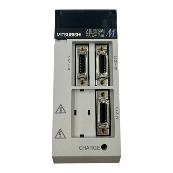
1. FUNCTIONS AND CONFIGURATION 1.7 Parts identification (1) Drive unit Mounting screw Status indicator LED Indicates the status of the drive unit. Blinking green: Servo off status Steady green: Servo on status Blinking red: Warning status Steady red: Alarm status Rating plate Encoder connector Connect the servo... - Page 24 1. FUNCTIONS AND CONFIGURATION (3) Base unit The following shows the MR-J2M-BU4. CON3A CNP1B First slot connector CON3C Control circuit power input connector Third slot connector CNP1A Regenerative brake option connector CON4 CNP3 Option slot connector Main circuit power input connector CON5 Battery unit connector CON1,CON2...
-
Page 25: Servo System With Auxiliary Equipment
1. FUNCTIONS AND CONFIGURATION 1.8 Servo system with auxiliary equipment To prevent an electric shock, always connect the protective earth (PE) terminal WARNING (terminal marked ) of the base unit to the protective earth (PE) of the control box. 3-phase 200V to 230VAC (Note) 1-phase 200V to 230VAC power supply Options and auxiliary equipment... - Page 26 1. FUNCTIONS AND CONFIGURATION MEMO 1 - 10 www.dadehpardazan.ir 88594014-15...
-
Page 27: Installation And Start Up
2. INSTALLATION AND START UP 2. INSTALLATION AND START UP Stacking in excess of the limited number of products is not allowed. Install the equipment to incombustibles. Installing them directly or close to combustibles will led to a fire. Install the equipment in a load-bearing place in accordance with this Instruction Manual. -
Page 28: Installation Direction And Clearances
2. INSTALLATION AND START UP 2.2 Installation direction and clearances The equipment must be installed in the specified direction. Otherwise, a fault may occur. CAUTION Leave specified clearances between each unit and control box inside walls or other equipment. (1) Installation of one MELSERVO-J2M 40mm(1.57inch) or more 40mm(1.57inch) or more (2) Installation of two or more MELSERVO-J2M... -
Page 29: Keep Out Foreign Materials
2. INSTALLATION AND START UP (3) Others When using heat generating equipment such as the regenerative brake option, install them with full consideration of heat generation so that MELSERVO-J2M is not affected. Install MELSERVO-J2M on a perpendicular wall in the correct vertical direction. 2.3 Keep out foreign materials (1) When installing the unit in a control box, prevent drill chips and wire fragments from entering each unit. -
Page 30: Mounting Method
2. INSTALLATION AND START UP 2.5 Mounting method (1) Base unit As shown below, mount the base unit on the wall of a control box or like with M5 screws. Wall (2) Interface unit/drive unit (MR-J2M-40DU or less) The following example gives installation of the drive unit to the base unit. The same also applies to the interface unit. - Page 31 2. INSTALLATION AND START UP Sectional view Wall 3) Tighten the M4 screw supplied for the base unit to fasten the drive unit to the base unit. POINT Securely tighten the drive unit fixing screw. Sectional view Wall (3) Drive unit (MR-J2M-70DU) When using the MR-J2M-70DU, install it on two slots of the base unit.
-
Page 32: When Switching Power On For The First Time
2. INSTALLATION AND START UP 2.6 When switching power on for the first time Before starting operation, check the following: (1) Wiring (a) Check that the control circuit power cable, main circuit power cable and servo motor power cable are fabricated properly. (b) Check that the control circuit power cable is connected to the CNP1B connector and the main circuit power cable is connected to the CNP3 connector. -
Page 33: Start Up
2. INSTALLATION AND START UP 2.7 Start up Do not operate the switches with wet hands. You may get an electric shock. Do not operate the controller with the front cover removed. High-voltage terminals WARNING and charging area exposed and you may get an electric shock. During power-on or operation, do not open the front cover. - Page 34 2. INSTALLATION AND START UP (2) Parameter setting Set the parameters according to the structure and specifications of the machine. Refer to Chapter 5 for the parameter definitions. (3) Checking the axis number On the interface unit display, check that the slot numbers and axis numbers are as set. Set the drive unit axis numbers in the IFU parameters No.
-
Page 35: Control Axis Selection
2. INSTALLATION AND START UP 2.8 Control axis selection POINT The control axis number set to the IFU parameter software should be the same as the one set to the servo system controller. Set the control axis numbers of the drive units in the IFU parameters No. 11 to 18. Setting the same control axis numbers in a single communication system will disable normal operation. - Page 36 2. INSTALLATION AND START UP MEMO 2 - 10 www.dadehpardazan.ir 88594014-15...
-
Page 37: Signals And Wiring
3. SIGNALS AND WIRING 3. SIGNALS AND WIRING Any person who is involved in wiring should be fully competent to do the work. Before starting wiring, make sure that the voltage is safe in the tester more than 15 minutes after power-off. Otherwise, you may get an electric shock. Ground the base unit and the servo motor securely. -
Page 38: Connection Example Of Control Signal System
3. SIGNALS AND WIRING 3.1 Connection example of control signal system POINT Refer to Section 3.4 for the connection of the power supply system and to Section 3.5 for connection with the servo motor. Interface unit (Note 5) (Note 5) (Note 2 6) 24VDC 13 MBR... - Page 39 12. Always insert the termination connector (MR-A-TM) into CN1B of the interface unit located at the termination. 13. The bus cable used with the SSCNET depends on the preceding or subsequent controller or servo amplifier connected. Refer to the following table and choose the bus cable. MR-J2M-P8B MR-J2S- MR-J2-03B5...
-
Page 40: I/O Signals Of Interface Unit
3. SIGNALS AND WIRING 3.2 I/O signals of interface unit 3.2.1 Connectors and signal arrangements POINT The pin configurations of the connectors are as viewed from the cable connector wiring section. CN1A CN1B Interface unit EMG* EMG* The connector frames are connected with the PE (earth) terminal inside the base unit. -
Page 41: Signal Explanations
3. SIGNALS AND WIRING 3.2.2 Signal explanations For the I/O interfaces (symbols in I/O column in the table), refer to Section 3.2.3. (1) Connector applications Connector Name Function/Application Used for connection with the controller or preceding-axis CN1A Connector for bus cable from preceding axis. servo amplifier. -
Page 42: Interfaces
3. SIGNALS AND WIRING 3.2.3 Interfaces (1) Common line The following diagram shows the power supply and its common line. Interface unit .etc 24VDC .etc Analog monitor DI-1 Base unit RS-232 Drive unit Servo motor encoder Servo motor Extension IO unit LA.etc Differential line LAR.etc... - Page 43 3. SIGNALS AND WIRING (2) Detailed description of the interfaces This section gives the details of the I/O signal interfaces (refer to I/O Division in the table) indicated in Sections 3.2.2. Refer to this section and connect the interfaces with the external equipment. (a) Digital input interface DI-1 Give a signal with a relay or open collector transistor.
- Page 44 3. SIGNALS AND WIRING 2) Lamp load Interface unit 24VDC (c) Analog output Output voltage : 4V Max. output current :0.5mA Resolution :10bit Interface unit (MO2 M03) 1mA meter which deflects unidirectionally or bidirectionally 3 - 8 www.dadehpardazan.ir 88594014-15...
-
Page 45: Signals And Wiring For Extension Io Unit
3. SIGNALS AND WIRING 3.3 Signals and wiring for extension IO unit 3.3.1 Connection example POINT The pins without symbols can be assigned any devices using the MR Configurator (servo configuration software). MR-J2M-D01 (Note 2) (Note 3) (Note 2) CN4A 24VDC (Note 1) CN4A... - Page 46 2. The signals having the same name are connected to the inside of the servo amplifier. 3. Always connect 24VDC (200mA). 4. These pins are unavailable when the MR-J2M-P8B is used as the interface unit. 3 - 10 www.dadehpardazan.ir 88594014-15...
-
Page 47: Connectors And Signal Configurations
3. SIGNALS AND WIRING 3.3.2 Connectors and signal configurations (1) Signal configurations POINT The pin configurations of the connectors are as viewed from the cable connector wiring section. CN4A CN4B LAR1 LAR5 LBR1 LBR5 LZR1 LZR5 LAR2 LAR6 LBR2 LBR6 LZR2 LZR6 LAR3... -
Page 48: Output Signal Explanations
3. SIGNALS AND WIRING 3.3.3 Output signal explanations For the IO interfaces (system in I/O column in the table), refer to section 3.2.3. Connector Signal Symbol Function/Applications pin No. division Encoder A-phase CN4A-50 As LA , LAR , LB and LBR , the pulses per servo motor revolution set DO-2 pulse 1 LAR1... - Page 49 3. SIGNALS AND WIRING Connector Signal Symbol Function/Applications pin No. division MBR1: Electromagnetic brake interlock signal for axis 1 Electromagnetic DO-1 MBR1 CN4A-9 MBR2: Electromagnetic brake interlock signal for axis 2 brake interlock 1 MBR3: Electromagnetic brake interlock signal for axis 3 Electromagnetic MBR4: Electromagnetic brake interlock signal for axis 4 MBR2 CN4A-10...
-
Page 50: Signals And Wiring For Base Unit
3. SIGNALS AND WIRING 3.4 Signals and wiring for base unit When each unit has become faulty, switch power off on the base unit power side. Continuous flow of a large current may cause a fire. Switch power off at detection of an alarm. Otherwise, a regenerative brake CAUTION transistor fault or the like may overheat the regenerative brake resistor, causing a fire. - Page 51 3. SIGNALS AND WIRING (2) For 1-phase 200 to 230VAC power supply Controller (Note 1) forced Forced Alarm stop stop MELSERVO-J2M CNP3 (Note 2) Power supply 1-phase 200 to 230VAC CNP1B 24VDC Forced stop Note 1. Configure up the power supply circuit which switches off the magnetic contactor after detection of alarm occurrence on the controller side.
-
Page 52: Connectors And Signal Configurations
3. SIGNALS AND WIRING 3.4.2 Connectors and signal configurations POINT The pin configurations of the connectors are as viewed from the cable connector wiring section. CNP1A CNP1B (X type) (Y type) Base unit CNP3 The connector frames are connected to the PE (earth) terminal of the base unit. -
Page 53: Terminals
3. SIGNALS AND WIRING 3.4.3 Terminals Refer to Section 10.2.1 for the layouts and signal configurations of the terminal blocks. Connection target Connector Pin No. Code Description (Application) (1) When using a three-phase power supply Supply L and L with three-phase, 200 to 230VAC, 50/60Hz power. -
Page 54: Power-On Sequence
3. SIGNALS AND WIRING 3.4.4 Power-on sequence (1) Power-on procedure 1) Always wire the power supply as shown in above Section 3.4.1 using the magnetic contactor with the main circuit power supply (3-phase 200V: L , 1-phase 200 to 230VAC: L ). -
Page 55: Connection Of Drive Unit And Servo Motor
3. SIGNALS AND WIRING 3.5 Connection of drive unit and servo motor 3.5.1 Connection instructions Connect the wires to the correct phase terminals (U, V, W) of the drive unit and servo motor. Otherwise, the servo motor will operate improperly. CAUTION Do not connect AC power supply directly to the servo motor. -
Page 56: I/O Terminals
3. SIGNALS AND WIRING 3.5.3 I/O terminals (1) Drive unit POINT The pin configurations of the connectors are as viewed from the cable connector wiring section. Drive unit CNP2 Cable side connector Connector Model Maker 1. Soldering type Connector: 10120-3000VE Shell kit: 10320-52F0-008 2. -
Page 57: Alarm Occurrence Timing Chart
3. SIGNALS AND WIRING 3.6 Alarm occurrence timing chart When an alarm has occurred, remove its cause, make sure that the operation signal is not being input, ensure safety, and reset the alarm before restarting CAUTION operation. As soon as an alarm occurs, make the Servo off status and interrupt the main circuit power. -
Page 58: Servo Motor With Electromagnetic Brake
3. SIGNALS AND WIRING 3.7 Servo motor with electromagnetic brake Configure the electromagnetic brake operation circuit so that it is activated not only by the interface unit signals but also by an external forced stop (EM1). Contacts must be open when Circuit must be servo-off, when an alarm occurrence opened during... - Page 59 3. SIGNALS AND WIRING (3) Electromagnetic brake interlock signal There are the following electromagnetic brake interlock signals. The MR-J2M-D01 is required to use MBR1 to MBR8. Load the MR-J2M-D01 to the option slot of the base unit. Signal Symbol Connector Pin No. Description Electromagnetic Electromagnetic brake interlock signal for all axes or the axis...
- Page 60 3. SIGNALS AND WIRING (b) Electromagnetic brake interlock 1 to 8 (MBR1 to MBR8) By adding an extension IO unit, you can use the electromagnetic brake interlock (MBR) for each axis. The timing chart is as shown in (4) of this section. (4) Timing charts (a) Servo-on command (from controller) ON/OFF Delay time (Tb) [ms] after the servo-on is switched off, the servo lock is released and the servo...
- Page 61 3. SIGNALS AND WIRING (c) Alarm occurrence Dynamic brake Dynamic brake Electromagnetic brake Servo motor speed Electromagnetic brake (10ms) Base circuit Electromagnetic Invalid(ON) Electromagnetic brake brake interlock operation delay time Valid(OFF) (MBR MBR1 to MBR8) No(ON) Trouble (ALM) Yes(OFF) (d) Both main and control circuit power supplies off Dynamic brake Dynamic brake Electromagnetic brake...
-
Page 62: Grounding
3. SIGNALS AND WIRING 3.8 Grounding Ground the base unit and servo motor securely. WARNING To prevent an electric shock, always connect the protective earth (PE) terminal of the base unit with the protective earth (PE) of the control box. The base unit switches the power transistor on-off to supply power to the servo motor. -
Page 63: Instructions For The 3M Connector
3. SIGNALS AND WIRING 3.9 Instructions for the 3M connector When fabricating an encoder cable or the like, securely connect the shielded external conductor of the cable to the ground plate as shown in this section and fix it to the connector shell. External conductor Sheath Core... - Page 64 3. SIGNALS AND WIRING MEMO 3 - 28 www.dadehpardazan.ir 88594014-15...
-
Page 65: Operation And Display
4. OPERATION AND DISPLAY 4. OPERATION AND DISPLAY On the interface unit display (5-digit, seven-segment display), check the status of communication with the servo system controller at power-on, check the axis number, and diagnose a fault at occurrence of an alarm. -
Page 66: Display Sequence
4. OPERATION AND DISPLAY 4.1.1 Display sequence @ in the diagram denotes the slot number of the base unit and # the axis number of the drive unit. MELSERVO-J2M power ON Waiting for servo system controller power to switch ON Servo system controller power ON Initial data communication with servo system controller... -
Page 67: If Alarm/Warning Occurs
4. OPERATION AND DISPLAY (1) Indication list (Note 1) Indication Status Description MELSERVO-J2M was switched on when power to the servo system controller @ Ab# Initializing is off. Power to the servo system controller was switched off during power-on of MELSERVO-J2M. -
Page 68: Status Display Mode Of Interface Unit
4. OPERATION AND DISPLAY 4.2 Status display mode of interface unit 4.2.1 Display flowchart Use the display (5-digit, 7-segment LED) on the front panel of the interface unit for status display, parameter setting, etc. Set the parameters before operation, diagnose an alarm, confirm external sequences, and/or confirm the operation status. -
Page 69: Status Display Of Interface Unit
4. OPERATION AND DISPLAY 4.2.2 Status display of interface unit MELSERVO-J2M status during operation is shown on the 5-digit, 7-segment LED display. Press the "UP" or "DOWN" button to change display data as desired. When the required data is selected, the corresponding symbol appears. -
Page 70: Diagnostic Mode Of Interface Unit
4. OPERATION AND DISPLAY 4.2.3 Diagnostic mode of interface unit Name Display Description Shows the ON/OFF states of the external I/O signals and whether a forced stop command from the servo system controller is present or not. 1) Forced stop command from servo system controller External I/O signal Absent: On Present: Off... -
Page 71: Alarm Mode Of Interface Unit
4. OPERATION AND DISPLAY 4.2.4 Alarm mode of interface unit The current alarm, past alarm history and parameter error are displayed. The lower 2 digits on the display indicate the alarm number that has occurred or the parameter number in error. Display examples are shown below. -
Page 72: Interface Unit Parameter Mode
4. OPERATION AND DISPLAY 4.2.5 Interface unit parameter mode The parameters whose abbreviations are marked* are made valid by changing the setting and then switching power off once and switching it on again. Refer to Section 5.2.2. The following example shows the operation procedure performed after power-on to change the serial communication baudrate (IFU parameter No. -
Page 73: Output Signal (Do) Forced Output
4. OPERATION AND DISPLAY 4.2.6 Output signal (DO) forced output POINT This function is available during test operation. The output signal can be forced on/off independently of the servo status. This function is used for output signal wiring check, etc. This operation must be performed in the servo off state. Call the display screen shown after power-on. - Page 74 4. OPERATION AND DISPLAY MEMO 4 - 10 www.dadehpardazan.ir 88594014-15...
-
Page 75: Parameters
5. PARAMETERS 5. PARAMETERS Never adjust or change the parameter values extremely as it will make operation CAUTION instable. POINT When MELSERVO-J2M is connected with the servo system controller, the parameters are set to the values of the servo system controller. Switching power off, then on makes the values set on the MR Configurator (servo configuration software) invalid and the servo system controller values valid. -
Page 76: Lists
5. PARAMETERS 5.1.2 Lists POINT For any DRU parameter whose symbol is preceded by*, set the DRU parameter value and switch power off once, then switch it on again to make that parameter setting valid. The parameter is set when communication between the servo system controller and servo amplifier is established (b* is displayed). - Page 77 5. PARAMETERS (Note) Classifi- Custome Symbol Name Unit Initial cation r setting Value For manufacturer setting 0000 0111 *CDP Gain changing selection 0000 Gain changing condition (Note) Gain changing time constant GD2B Ratio of load inertia moment to Servo motor inertia moment 2 times PG2B Position control gain 2 changing ratio...
- Page 78 5. PARAMETERS (2) Details list Classifi- Initial Setting Symbol Name and Function Unit cation Value Range *AMS Amplifier setting 0000 Refer to Used to select the absolute position detection. name function column. Absolute position detection selection 0: Invalid (Used in incremental system.) 1: Valid (Used in absolute position detection system.) *REG...
- Page 79 5. PARAMETERS Classifi- Initial Setting Symbol Name and Function Unit cation Value Range *POL Rotation direction selection Refer to Used to select the rotation direction of the servo motor. name 0: Forward rotation (CCW) with the increase of the positioning address.
- Page 80 5. PARAMETERS Classifi- Initial Setting Symbol Name and Function Unit cation Value Range Servo response 0005 Refer to Used to select the response level of auto tuning. name function column. Auto tuning response level selection Response Machine resonance value level frequency guideline 15Hz response...
- Page 81 5. PARAMETERS Classifi- Initial Setting Symbol Name and Function Unit cation Value Range Speed loop gain 1 rad/s Normally this parameter setting need not be changed. Higher setting increases the response level but is liable to generate vibration and/or 5000 noise.
- Page 82 5. PARAMETERS Classifi- Initial Setting Symbol Name and Function Unit cation Value Range In-position range pulse Used to set the droop pulse range in which the in-position (INP) will be output to the controller. Make setting in the feedback pulse unit 50000 (parameter No.
- Page 83 5. PARAMETERS Classifi- Initial Setting Symbol Name and Function Unit cation Value Range Low-pass filter/adaptive vibration suppression control 0000 Refer to Used to select the low-pass filter and adaptive vibration suppression name control. (Refer to Chapter 7.) function column. Low-pass filter selection 0: Valid (Automatic adjustment) 1: Invalid VG2 setting 10...
- Page 84 5. PARAMETERS Classifi- Initial Setting Symbol Name and Function Unit cation Value Range *OP6 Option function 6 0000 Refer to Used to select the serial communication baudrate, serial name communication response delay time setting and encoder output pulse setting. function column.
- Page 85 5. PARAMETERS Classifi- Initial Setting Symbol Name and Function Unit cation Value Range For manufacturer setting Do not change this value by any means. *BLK DRU Parameter blocks write inhibit 0000 Refer to name Operation from MR Operation from Configurator (servo Setting Operation function...
- Page 86 5. PARAMETERS Initial Setting Class Symbol Name and function Unit value range For manufacturer setting Do not change this value by any means. 0000 0111 *CDP Gain changing selection 0000 Refer to Used to select the gain changing condition. (Refer to Section 7.5.) Name function column...
- Page 87 5. PARAMETERS Initial Setting Class Symbol Name and function Unit value range *OPC Optional function C 0000 Refer to Use to select the encoder output pulse direction. Name function column Encoder pulse output phase changing Changes the phases of A, B-phase encoder pulses output . Servo motor rotation direction Set value A phase...
- Page 88 5. PARAMETERS Initial Setting Class Symbol Name and function Unit value range For manufacturer setting 0000 Do not change this value by any means. 5 - 14 www.dadehpardazan.ir 88594014-15...
-
Page 89: Interface Unit
5. PARAMETERS 5.2 Interface unit 5.2.1 IFU parameter write inhibit POINT Use the unit operation section pushbutton switches or MR Configurator (servo configuration software) to set the IFU parameters of the interface unit. They cannot be set from the servo system controller. Use the unit pushbutton switches or MR Configurator (servo configuration software) to set the interface unit parameters. - Page 90 5. PARAMETERS (2) Details list Classifi- Initial Setting Symbol Name and Function Unit cation Value Range *BPS Serial communication function selection, alarm history clear 0000 Refer to Used to select the serial communication baudrate, select various name communication conditions, and clear the alarm history. function column.
- Page 91 5. PARAMETERS Classifi- Initial Setting Symbol Name and Function Unit cation Value Range *MD1 Analog monitor 1 output 0000 Refer to Choose the signal to be output to analog monitor 1. name function column. Analog monitor 1 selection 0: Servo motor speed ( 4V/max. Servo motor speed) 1: Torque ( 4V/max.
- Page 92 5. PARAMETERS Classifi- Initial Setting Symbol Name and Function Unit cation Value Range *MD3 Analog monitor 3 output 0000 Refer to Choose the signal to be output to analog monitor 3. name function column. Analog monitor 3 selection 0: Servo motor speed ( 4V/max. Servo motor speed) 1: Torque ( 4V/max.
- Page 93 5. PARAMETERS Classifi- Initial Setting Symbol Name and Function Unit cation Value Range *SSC SSCNET type selection 0200 Refer to Select the network type of the interface unit. name function column. SSCNET type selection 00: SSCNET3.5ms 01: SSCNET1.7ms 02: SSCNET0.8ms 12: SSCNET POINT When using motion controller Q series, set the communication...
- Page 94 5. PARAMETERS Classifi- Initial Setting Symbol Name and Function Unit cation Value Range *SL1 Slot 1 axis number selection 0000 0000 Choose the axis number of the drive unit connected to the first slot of the base unit. (Refer to Section 2.8) 0007h Axis number set value...
-
Page 95: Analog Monitor
5. PARAMETERS 5.2.3 Analog monitor The servo status can be output to 3 channels in terms of voltage. Using an ammeter enables monitoring the servo status. (1) Setting Change the following digits of IFU parameter No.3 to 5: IFU parameter No. 3 Analog monitor 1 selection (Signal output to across MO1-LG) Axis number of analog monitor 1... - Page 96 5. PARAMETERS Setting Output item Data Setting Output item Data Servo motor speed Droop pulses CCW direction 4[V] ( 4V/32768pulse) 4[V] direction direction 32768[pulse] 32768[pulse] Max. speed Max. speed 4[V] CW direction Torque (Note) Droop pulses CCW direction 4[V] Driving in Driving in ( 4V/131072pulse) CW direction...
- Page 97 5. PARAMETERS (3) Analog monitor block diagram 5 - 23 www.dadehpardazan.ir 88594014-15...
-
Page 98: Test Operation Mode
5. PARAMETERS 5.2.4 Test operation mode The test operation mode is designed for servo operation confirmation and not for machine operation confirmation. Do not use this mode with the machine. Always CAUTION use the servo motor alone. If an operation fault occurred, use the forced stop (EM1) to make a stop. By using a personal computer and the MR Configurator (servo configuration software), you can execute jog operation, positioning operation, motor-less operation and DO forced output without connecting the servo system controller. - Page 99 5. PARAMETERS 1) Operation pattern Item Initial value Setting range Travel [pulse] 100000 0 to 9999999 Speed [r/min] 0 to max. speed Acceleration/deceleration time constant [ms] 1000 1 to 50000 2) Operation method Operation Screen control Forward rotation start "Click Forward" button. Reverse rotation start "Click Reverse"...
- Page 100 5. PARAMETERS (e) Output signal (DO) forced output Output signals can be switched on/off forcibly independently of the servo status. Use this function for output signal wiring check, etc. Exercise control on the DO forced output screen of the MR Configurator (servo configuration software).
-
Page 101: General Gain Adjustment
6. GENERAL GAIN ADJUSTMENT 6. GENERAL GAIN ADJUSTMENT 6.1 Different adjustment methods 6.1.1 Adjustment on a MELSERVO-J2M The gain adjustment in this section can be made on MELSERVO-J2M. For gain adjustment, first execute auto tuning mode 1. If you are not satisfied with the results, execute auto tuning mode 2, manual mode 1 and manual mode 2 in this order. - Page 102 6. GENERAL GAIN ADJUSTMENT (2) Adjustment sequence and mode usage START Usage Used when you want to Interpolation made for 2 or more match the position gain 1 axes? (PG1) between 2 or more Interpolation mode axes. Normally not used for other purposes.
-
Page 103: Adjustment Using Mr Configurator (Servo Configuration Software)
6. GENERAL GAIN ADJUSTMENT 6.1.2 Adjustment using MR Configurator (servo configuration software) This section gives the functions and adjustment that may be performed by using MELSERVO-J2M with the MR Configurator (servo configuration software) which operates on a personal computer. Function Description Adjustment Machine analyzer... -
Page 104: Auto Tuning
6. GENERAL GAIN ADJUSTMENT 6.2 Auto tuning 6.2.1 Auto tuning mode MELSERVO-J2M has a real-time auto tuning function which estimates the machine characteristic (load inertia moment ratio) in real time and automatically sets the optimum gains according to that value. This function permits ease of gain adjustment of MELSERVO-J2M. -
Page 105: Auto Tuning Mode Operation
6. GENERAL GAIN ADJUSTMENT 6.2.2 Auto tuning mode operation The block diagram of real-time auto tuning is shown below. Load inertia Automatic setting moment Encoder Control gains Command Current Servo PG1,VG1 control motor PG2,VG2,VIC Current feedback Real-time auto Position/speed Set 0 or 1 to turn on. tuning section feedback Load inertia... -
Page 106: Adjustment Procedure By Auto Tuning
6. GENERAL GAIN ADJUSTMENT 6.2.3 Adjustment procedure by auto tuning Since auto tuning is made valid before shipment from the factory, simply running the servo motor automatically sets the optimum gains that match the machine. Merely changing the response level setting value as required completes the adjustment. -
Page 107: Response Level Setting In Auto Tuning Mode
6. GENERAL GAIN ADJUSTMENT 6.2.4 Response level setting in auto tuning mode Set the response (DRU parameter No.9) of the whole servo system. As the response level setting is increased, the trackability and settling time for a command decreases, but a too high response level will generate vibration. -
Page 108: Manual Mode 1 (Simple Manual Adjustment)
6. GENERAL GAIN ADJUSTMENT 6.3 Manual mode 1 (simple manual adjustment) If you are not satisfied with the adjustment of auto tuning, you can make simple manual adjustment with three DRU parameters. 6.3.1 Operation of manual mode 1 In this mode, setting the three gains of position control gain 1 (PG1), speed control gain 2 (VG2) and speed integral compensation (VIC) automatically sets the other gains to the optimum values according to these gains. - Page 109 6. GENERAL GAIN ADJUSTMENT (c) Adjustment description 1) Speed control gain 2 (DRU parameter No. 16) This parameter determines the response level of the speed control loop. Increasing this value enhances response but a too high value will make the mechanical system liable to vibrate. The actual response frequency of the speed loop is as indicated in the following expression: Speed control gain setting Speed loop response frequency(Hz)
- Page 110 6. GENERAL GAIN ADJUSTMENT (c) Adjustment description 1) Position control gain 1 (DRU parameter No. 13) This parameter determines the response level of the position control loop. Increasing position control gain 1 improves trackability to a position command but a too high value will make overshooting liable to occur at the time of settling.
-
Page 111: Interpolation Mode
6. GENERAL GAIN ADJUSTMENT 6.4 Interpolation mode The interpolation mode is used to match the position control gains of the axes when performing the interpolation operation of servo motors of two or more axes for an X-Y table or the like. In this mode, the position control gain 1 and speed control gain 1 which determine command trackability are set manually and the other gain adjusting parameters are set automatically. - Page 112 6. GENERAL GAIN ADJUSTMENT MEMO 6 - 12 www.dadehpardazan.ir 88594014-15...
-
Page 113: Special Adjustment Functions
7. SPECIAL ADJUSTMENT FUNCTIONS 7. SPECIAL ADJUSTMENT FUNCTIONS POINT The functions given in this chapter need not be used generally. Use them if you are not satisfied with the machine status after making adjustment in the methods in Chapter 6. If a mechanical system has a natural resonance level point, increasing the servo system response may cause the mechanical system to produce resonance (vibration or unusual noise) at that resonance frequency. - Page 114 7. SPECIAL ADJUSTMENT FUNCTIONS (2) Parameters Set the notch frequency and notch depth of the machine resonance suppression filter 1 (DRU parameter No. 18). DRU parameter No. 18 Notch frequency selection Setting Frequency Setting Frequency Setting Frequency Setting Frequency Invalid 562.5 281.3 187.5...
-
Page 115: Adaptive Vibration Suppression Control
7. SPECIAL ADJUSTMENT FUNCTIONS 7.3 Adaptive vibration suppression control (1) Function Adaptive vibration suppression control is a function in which the drive unit detects machine resonance and sets the filter characteristics automatically to suppress mechanical system vibration. Since the filter characteristics (frequency, depth) are set automatically, you need not be conscious of the resonance frequency of a mechanical system. -
Page 116: Low-Pass Filter
7. SPECIAL ADJUSTMENT FUNCTIONS (2) Parameters The operation of adaptive vibration suppression control selection (DRU parameter No.25). DRU parameter No. 25 Adaptive vibration suppression control selection 0: Invalid 1: Valid Machine resonance frequency is always detected to generate the filter in response to resonance, suppressing machine vibration. -
Page 117: Gain Changing Function
7. SPECIAL ADJUSTMENT FUNCTIONS 7.5 Gain changing function This function can change the gains. You can change between gains during rotation and gains during stop or can use an external signal to change gains during operation. 7.5.1 Applications This function is used when: (1) You want to increase the gains during servo lock but decrease the gains to reduce noise during rotation. -
Page 118: Parameters
7. SPECIAL ADJUSTMENT FUNCTIONS 7.5.3 Parameters When using the gain changing function, always set " " in DRU parameter No.2 (auto tuning) to choose the manual mode 1 of the gain adjustment modes. The gain changing function cannot be used in the auto tuning mode. - Page 119 7. SPECIAL ADJUSTMENT FUNCTIONS (1) DRU Parameters No. 12 to 17 These parameters are the same as in ordinary manual adjustment. Gain changing allows the values of ratio of load inertia moment to servo motor inertia moment, position control gain 2, speed control gain 2 and speed integral compensation to be changed.
-
Page 120: Gain Changing Operation
7. SPECIAL ADJUSTMENT FUNCTIONS 7.5.4 Gain changing operation This operation will be described by way of setting examples. (1) When you choose changing by external input (a) Setting DRU Parameter No. Abbreviation Name Setting Unit Position control gain 1 rad/s Speed control gain 1 1000 rad/s... - Page 121 7. SPECIAL ADJUSTMENT FUNCTIONS (2) When you choose changing by droop pulses (a) Setting DRU Parameter No. Abbreviation Name Setting Unit Position control gain 1 rad/s Speed control gain 1 1000 rad/s Ratio of load inertia moment to 0.1 times servo motor inertia moment Position control gain 2 rad/s...
- Page 122 7. SPECIAL ADJUSTMENT FUNCTIONS MEMO 7 - 10 www.dadehpardazan.ir 88594014-15...
- Page 123 8. INSPECTION 8. INSPECTION Before starting maintenance and/or inspection, make sure that the charge lamp is off more than 15 minutes after power-off. Then, confirm that the voltage is safe in the tester or the like. Otherwise, you may get an electric shock. WARNING Any person who is involved in inspection should be fully competent to do the work.
- Page 124 8. INSPECTION MEMO 8 - 2 www.dadehpardazan.ir 88594014-15...
-
Page 125: Troubleshooting
9. TROUBLESHOOTING 9. TROUBLESHOOTING 9.1 Alarms and warning list POINT The alarm/warning whose indication is not given does not exist in that unit. When a fault occurs during operation, the corresponding alarm or warning is displayed. If any alarm or warning has occurred, refer to Section 9.2 or 9.3 and take the appropriate action. - Page 126 9. TROUBLESHOOTING Alarm deactivation Display Name Error reset CPU reset A.10 Undervoltage A.12 Memory error 1 A.13 Clock error A.14 Watchdog A.15 Memory error 2 A.16 Encoder error 1 A.17 Board error A.19 Memory error 3 A.1A Motor combination error A.1B Axis set error A.1C...
-
Page 127: Remedies For Alarms
9. TROUBLESHOOTING 9.2 Remedies for alarms When any alarm has occurred, eliminate its cause, ensure safety, then reset the alarm, and restart operation. Otherwise, injury may occur. If an absolute position erase (A.25) occurred, always make home position setting CAUTION again. - Page 128 9. TROUBLESHOOTING Display Name Definition Cause Action @A.12# Memory error 1 RAM, memory fault Faulty parts in the drive unit. Change the drive unit. @A.13# Clock error Printed board fault. Checking method Alarm (any of A.12 to 15) @A.14# Watchdog CPU/parts fault occurs if power is switched on @A.15# Memory error 2 EEP-ROM fault...
- Page 129 9. TROUBLESHOOTING Display Name Definition Cause Action @A.20# Encoder error 2 Communication error 1. Encoder connector (CN2) Connect correctly. occurred between disconnected. encoder and drive 2. Encoder fault. Change the servo motor. unit. 3. Encoder cable faulty. Repair or change cable. (Wire breakage or shorted) @A.24# Main circuit Ground fault occurred...
- Page 130 9. TROUBLESHOOTING Display Name Definition Cause Action @A.31# Overspeed Speed has exceeded 1. Small acceleration/deceleration time Increase acceleration/ the instantaneous constant caused overshoot to be deceleration time constant. permissible speed. large. 2. Servo system is instable to cause 1. Reset servo gain to proper overshoot.
- Page 131 9. TROUBLESHOOTING Display Name Definition Cause Action FA.37 IFU parameter IFU parameter setting 1. Interface unit fault caused the IFU Change the interface unit. error is wrong. parameter setting to be rewritten. 2. There is a IFU parameter whose Change the IFU parameter value value was set to outside the setting to within the setting range.
- Page 132 9. TROUBLESHOOTING Display Name Definition Cause Action @A.51# Overload 2 Machine collision or 1. Machine struck something. 1. Review operation pattern. the like caused max. 2. Install limit switches. output current to flow 2. Wrong connection of servo motor. Connect correctly. successively for Drive unit's output U, V, W do not several seconds.
- Page 133 9. TROUBLESHOOTING Display Name Definition Cause Action FA.53 Multiple axis Drive unit whose 1. Drive unit having large load is 1. Change the slot of the drive overload effective load factor is adjacent. unit whose load is large. 85% or more is 2.
-
Page 134: Remedies For Warnings
9. TROUBLESHOOTING 9.3 Remedies for warnings POINT When any of the following alarms has occurred, do not resume operation by switching power of the servo amplifier OFF/ON repeatedly. The servo amplifier and servo motor may become faulty. If the power of the servo amplifier is switched OFF/ON during the alarms, allow more than 30 minutes for cooling before resuming operation. -
Page 135: Outline Drawings
350 (13.78) 6 (0.24) 6 (0.24) 338 (13.31) MELSERVO MELSERVO MELSERVO MELSERVO MELSERVO MELSERVO MELSERVO MELSERVO MITSUBISHI ELECTRIC MITSUBISHI ELECTRIC MITSUBISHI ELECTRIC MITSUBISHI ELECTRIC MITSUBISHI ELECTRIC MITSUBISHI ELECTRIC MITSUBISHI ELECTRIC MITSUBISHI ELECTRIC CON4 CON5 Approx. 70 (2.76) Approx. 70 (2.76) 158 (6.22) -
Page 136: Unit Outline Drawings
Tightening torque:1.2 [N m] (10.6 [lb in]) 2 (0.08) 2- 6 ( 0.24) mounting hole Mounting screw: M5 Tightening torque:3.24 [N m] (28.7 [lb in]) 10.2.2 Interface unit (MR-J2M-P8B) [Unit: mm] ([Unit: in]) 4.5 ( 0.18) mounting hole Approx. 70 130 (5.12) 139 (5.47) -
Page 137: Drive Unit (Mr-J2M- Du)
10 OUTLINE DRAWINGS 10.2.3 Drive unit (MR-J2M- (1) MR-J2M-10DU to MR-J2M-40DU [Unit: mm] ([Unit: in]) Approx. 70 (2.76) 138.5 (5.45) 4.5 ( 0.18) Connector layout 130 (4.72) (0.20) 6.5 (0.26) mounting hole (1.18) CNP2 MITSUBISHI MELSERVO NAME PLATE Mounting screw: M4 MITSUBISHI Tightening torque:1.5 [N m] NAME PLATE... -
Page 138: Extension Io Unit (Mr-J2M-D01)
10 OUTLINE DRAWINGS 10.2.4 Extension IO unit (MR-J2M-D01) [Unit: mm] ([Unit: in]) 138.5 (5.45) Approx. 80 (3.15) 130 (4.72) 5 (0.20) (0.89) 6.5 (0.26) 2- 4.5 ( 0.18) mounting hole Mounting screw: M4 Tightening torque:1.5 [N m] (13.3 [lb in]) NAME PLATE Mass: 0.2kg (1.10lb) 10.2.5 Battery unit (MR-J2M-BT) -
Page 139: Connector
10 OUTLINE DRAWINGS 10.3 Connector (1) CN1A CN1B CN2 CN3 connector <3M> (a) Soldered type Model Connector : 10120-3000VE Shell kit : 10320-52F0-008 [Unit: mm] ([Unit: in]) 12.0 (0.47) 14.0 (0.55) 22.0 (0.87) Logo, etc. are indicated here. 33.3 (1.31) 12.7 (0.50) (b) Threaded type... - Page 140 10 OUTLINE DRAWINGS (c) Insulation displacement type Model Connector : 10120-6000EL Shell kit : 10320-3210-000 [Unit: mm] ([Unit: in]) 6.7 ( 0.26) Logo, etc. are 20.9 (0.82) 2- 0.5 indicated here. ( 0.02) 29.7 (1.17) 10 - 6 www.dadehpardazan.ir 88594014-15...
- Page 141 10 OUTLINE DRAWINGS (2) CN4A CN4B connector <3M> (a) Soldered type Model Connector : 10150-3000VE Shell kit : 10350-52F0-008 [Unit: mm] ([Unit: in]) 17.0 (0.67) 46.5 (1.83) 18.0 (0.71) 41.1 (1.62) Logo, etc. are indicated here. 52.4 (2.06) 12.7 (0.50) (b) Threaded type Model Connector : 10150-3000VE Shell kit...
- Page 142 10 OUTLINE DRAWINGS (3) CNP1A CNP1B connector <Tyco Electronics> Model CNP1A housing : 1-178128-3 CNP1B housing : 2-178128-3 Contact : 917511-2 (max. sheath OD: 2.8 [mm]) 353717-2 (max. sheath OD: 3.4 [mm]) Applicable tool : 91560-1 (for 917511-2) 937315-1 (for 353717-2) [Unit: mm] 5.08 (0.2) ([Unit: in])
- Page 143 10 OUTLINE DRAWINGS (5) CNP1 CNP2 CNP3 connector <molex> [Unit: mm] 0.6 (0.024) ([Unit: in]) R0.3 Circuit number 3 (0.118) Layout diagrams classified by the number of poles (0.047) 5.4 (0.213) 11.6 5.4 (0.213) (0.457) 4 poles (0.059) Variable Dimensions (0.118) Model (0.138)
- Page 144 10 OUTLINE DRAWINGS (6) Bus cable connector Honda Tsushin Industry HDR type Model HDR Number of Pins Connector Connector case (Note) Crimping terminal HDR-E14MG1 HDR-E14LPA5 Wire straightening tool : FHAT-0029 Insulation displacement tool : FHPT-0004C HDR-E26MG1 HDR-E26LPA5 Note. Not available from us and to be supplied by the customer. Model Connector : HDR-E14MG1 Model Connector...
-
Page 145: Characteristics
11. CHARACTERISTICS 11. CHARACTERISTICS 11.1 Overload protection characteristics An electronic thermal relay is built in the drive unit to protect the servo motor and drive unit from overloads. Overload 1 alarm (A.50) occurs if overload operation performed is above the electronic thermal relay protection curve shown in any of Figs. -
Page 146: Power Supply Equipment Capacity And Generated Loss
HC-MFS43 4.32 HC-KFS73 7.54 MR-J2M-70DU HC-MFS73 7.54 HC-UFS73 7.54 MR-J2M-P8B 2.16 MR-J2M-BU4 1.08 MR-J2M-BU6 1.08 MR-J2M-BU8 1.08 Note 1. Note that the power supply capacity will vary according to the power supply impedance. This value applies to the case where the power factor improving reactor is not used. - Page 147 11. CHARACTERISTICS (2) Heat dissipation area for enclosed drive unit The enclosed control box (hereafter called the control box) which will contain the drive unit should be designed to ensure that its temperature rise is within 10 at the ambient temperature of 40 . (With a 5 (41 ) safety margin, the system should operate within a maximum 55 (131 ) limit.)
-
Page 148: Dynamic Brake Characteristics
11. CHARACTERISTICS 11.3 Dynamic brake characteristics Fig. 11.3 shows the pattern in which the servo motor comes to a stop when the dynamic brake is operated. Use Equation 11.2 to calculate an approximate coasting distance to a stop. The dynamic brake time constant varies with the servo motor and machine operation speeds. - Page 149 11. CHARACTERISTICS 0.02 0.018 0.016 0.014 0.012 0.01 0.008 0.006 0.004 0.002 500 1000 1500 2000 2500 3000 500 1000 1500 2000 2500 3000 Speed [r/min] Speed [r/min] a. HC-KFS series b. HC-MFS series 0.07 0.06 0.05 0.04 0.03 0.02 0.01 50 500 1000 1500 2000 2500 3000 Speed [r/min]...
-
Page 150: Encoder Cable Flexing Life
11. CHARACTERISTICS 11.4 Encoder cable flexing life The flexing life of the cables is shown below. This graph calculated values. Since they are not guaranteed values, provide a little allowance for these values. 1 10 5 10 1 10 a : Long flexing-life encoder cable 5 10 MR-JCCBL M-H 1 10... -
Page 151: Options And Auxiliary Equipment
12. OPTIONS AND AUXILIARY EQUIPMENT 12. OPTIONS AND AUXILIARY EQUIPMENT Before connecting any option or auxiliary equipment, make sure that the charge WARNING lamp is off more than 15 minutes after power-off, then confirm the voltage with a tester or the like. Otherwise, you may get an electric shock. Use the specified auxiliary equipment and options. - Page 152 12. OPTIONS AND AUXILIARY EQUIPMENT Calculate the total of the 3000r/min-equivalent inertia moments of the axes to be decelerated simultaneously, and find the maximum total of 3000r/min-equivalent inertia moments. Also find the sum total of permissible load inertia moments of the drive units installed on the same base unit.
- Page 153 12. OPTIONS AND AUXILIARY EQUIPMENT (b) To make selection according to regenerative energy Use the following method when regeneration occurs continuously in vertical motion applications or when it is desired to make an in-depth selection of the regenerative brake option: 1) Regenerative energy calculation Use the following table to calculate the regenerative energy.
- Page 154 12. OPTIONS AND AUXILIARY EQUIPMENT <Entry example> Timing First axis Second axis Third axis Fourth axis Fifth axis Sixth axis Seventh axis Eighth axis Total E 1) E 2) E 3) E 4) E 5) E 6) E 7) E 8) Regenerative ES ES 3) ES 4)
- Page 155 12. OPTIONS AND AUXILIARY EQUIPMENT (3) Connection of the regenerative brake option POINT When using the MR-RB54, cooling by a fan is required. Please obtain a cooling fan at your discretion. Set DRU parameter No.2 according to the option to be used. The regenerative brake option will cause a temperature rise of 100 degrees relative to the ambient temperature.
- Page 156 12. OPTIONS AND AUXILIARY EQUIPMENT (4) Outline drawing (a) MR-RB032 MR-RB14 [Unit: mm (in)] 6 (0.24) mounting hole MR-RB 5 (0.20) Terminal block Terminal screw: M3 Tightening torque: 0.5 to 0.6 [N m](4 to 5 [lb in]) Mounting screw 1.6 (0.06) 6 (0.23) Screw size: M5 (0.79)
- Page 157 12. OPTIONS AND AUXILIARY EQUIPMENT (b) MR-RB34 [Unit: mm (in)] Terminal block Terminal screw: M4 Tightening torque: 1.2 [N m] (10.6 [lb in]) Mounting screw Screw : M6 Tightening torque: 5.4 [N m](47.79 [lb in]) 318 (12.52) 90 (3.54) 335 (13.19) 10 (0.39) (0.67) 100 (3.94)
-
Page 158: Cables And Connectors
(Note) 1) 2) 3) Note. The bus cable used with the SSCNET depends on the preceding or subsequent controller or servo amplifier connected. Refer to the following table and choose the bus cable. MR-J2M-P8B MR-J2S- MR-J2-03B5 QD75M 7) Bus cable :MR-J2HBUS... - Page 159 12. OPTIONS AND AUXILIARY EQUIPMENT Product Model Description Application Standard encoder MR-JCCBL M-L Connector: 10120-3000VE Housing: 1-172161-9 Standard cable Refer to (2) (a) in Shell kit: 10320-52F0-008 Pin: 170359-1 flexing life this section. (3M or equivalent) (Tyco Electronics or equivalent) IP20 Cable clamp: MTI-0002 Long flexing life...
- Page 160 12. OPTIONS AND AUXILIARY EQUIPMENT Product Model Description Application 15) Power supply MR-PWCNK3 Plug: 5557-04R-210 Servo motor connector Terminal: 5556PBT3L (for AWG16) (6 pcs.) power cable (Molex) 16) Base unit MR-J2MCNM Housing: 2-178128-3 (5 pcs.) For CNP1B connector set Contact: 917511-2 (max. sheath OD 2.8 [mm] 15 pcs.) (Tyco Electronics)
- Page 161 12. OPTIONS AND AUXILIARY EQUIPMENT (2) Encoder cable If you have fabricated the encoder cable, connect it correctly. CAUTION Otherwise, misoperation or explosion may occur. POINT The encoder cable is not oil resistant. Refer to Section 11.4 for the flexing life of the encoder cable. When the encoder cable is used, the sum of the resistance values of the cable used for P5 and the cable used for LG should be within 2.4 .
- Page 162 12. OPTIONS AND AUXILIARY EQUIPMENT MR-JCCBL10M-L MR-JCCBL10M-H MR-JCCBL2M-L MR-JCCBL5M-L MR-JCCBL2M-H MR-JCCBL20M-L MR-JCCBL20M-H MR-JCCBL5M-H Drive unit side Encoder side Drive unit side Encoder side Drive unit side Encoder side (Note) (Note) (Note) Plate Plate Plate Note. Always make connection for use in an absolute position detection system. This wiring is not needed for use in an incremental system.
- Page 163 12. OPTIONS AND AUXILIARY EQUIPMENT (b) MR-JC4CBL M-H POINT When using this encoder cable, set " " in DRU parameter No. 23. 1) Model explanation Model: MR-JC4CBL Long flexing life Symbol Cable Length [m(ft)] 30 (98.4) 40 (131.2) 50 (164.0) 2) Connection diagram The signal assignment of the encoder connector is as viewed from the pin side.
- Page 164 12. OPTIONS AND AUXILIARY EQUIPMENT When fabricating an encoder cable, use the recommended wires given in Section 12.2.1 and the MR-J2CNM connector set for encoder cable fabrication, and fabricate an encoder cable as shown in the following wiring diagram. Referring to this wiring diagram, you can fabricate an encoder cable of up to 50m (164.0ft) length.
- Page 165 12. OPTIONS AND AUXILIARY EQUIPMENT (3) Communication cable POINT This cable may not be used with some personal computers. After fully examining the signals of the RS-232C connector, refer to this section and fabricate the cable. (a) Model definition Model : MR-CPCATCBL3M Cable length 3[m](10[ft]) (b) Connection diagram MR-CPCATCBL3M...
- Page 166 12. OPTIONS AND AUXILIARY EQUIPMENT (4) Bus cable When fabricating the bus cable, do not make incorrect connection. Doing so can CAUTION cause misoperation or explosion. When fabricating this cable, use the recommended cable given in Section 12.2.1 and fabricate it in accordance with the connection diagram shown in this section.
- Page 167 12. OPTIONS AND AUXILIARY EQUIPMENT (b) MR-J2HBUS M 1) Model definition Model:MR-J2HBUS Symbol Cable Length [m(ft)] 0.5 (1.64) 1 (3.28) 5 (16.4) 2) Connection diagram MR-J2HBUS 10120-6000EL(Connector) 10120-6000EL(Connector) 10320-3210-000(Shell kit) 10320-3210-000(Shell kit) EMG* Plate Plate 12 - 17 www.dadehpardazan.ir 88594014-15...
- Page 168 12. OPTIONS AND AUXILIARY EQUIPMENT (c) Q172J2BCBL M(-B) When using the battery unit Q170BAT, use the Q172J2BCBL M-B. For the Q170BAT, refer to the Motion Controller Q Series User's Manual (IB(NA)0300021). 1) Model definition Model:Q172J2BCBL Symbol Connection of Battery Unit Symbol Cable Length [m(ft)] 0.5 (1.64)
- Page 169 12. OPTIONS AND AUXILIARY EQUIPMENT 2) Connection diagram Q173J2B When HDR-E26MG1(Connector) 10120-6000EL(Connector) HDR-E26-LPA5(Connector case) 10320-3210-000(Connector case) SSCNET1 Line TD1* RD1* = No EMG12 EMG12* EMG* Plate SSCNET2 Line TD2* RD2* EMG* Plate SSCNET3 Line TD3* RD3* EMG34 EMG34* EMG* Plate SSCNET4 Line TD4* RD4*...
- Page 170 12. OPTIONS AND AUXILIARY EQUIPMENT (5) Battery cable When fabricating, use the recommended wire given in Section 12.2.1 and fabricate as in the connection diagram shown in this section. (a) Definition of model Model: MR-J2MBTCBL M Symbol Cable Length L [m(ft)] 0.3 (0.1) 1 (3.28) (b) Outline drawing...
-
Page 171: Maintenance Junction Card (Mr-J2Cn3Tm)
12. OPTIONS AND AUXILIARY EQUIPMENT 12.1.3 Maintenance junction card (MR-J2CN3TM) (1) Usage The maintenance junction card (MR-J2CN3TM) is designed for use when a personal computer and analog monitor are used at the same time. Interface unit Maintenance junction card (MR-J2CN3TM) Communication cable Bus cable MR-J2HBUS M... - Page 172 12. OPTIONS AND AUXILIARY EQUIPMENT (3) Outline drawing [Unit: mm] ([Unit: in]) CN3A CN3B CN3C 2- 5.3(0.21)(mounting hole) 3(0.12) 88(3.47) 41.5(1.63) 100(3.94) Mass: 110g(0.24Ib) 12 - 22 www.dadehpardazan.ir 88594014-15...
-
Page 173: Mr Configurator (Servo Configurations Software)
12. OPTIONS AND AUXILIARY EQUIPMENT 12.1.4 MR Configurator (servo configurations software) POINT Required to assign devices to the pins of CN4A and CN4B of the MR- J2M-D01 extension IO unit. The MR Configurator (servo configuration software) uses the communication function of the interface unit to perform parameter setting changes, graph display, test operation, etc. - Page 174 12. OPTIONS AND AUXILIARY EQUIPMENT (b) Configuration diagram Personal computer DRU (First axis) Communication cable Servo motor To RS-232C connector DRU (Eighth axis) Servo motor 12 - 24 www.dadehpardazan.ir 88594014-15...
-
Page 175: Auxiliary Equipment
12. OPTIONS AND AUXILIARY EQUIPMENT 12.2 Auxiliary equipment Always use the devices indicated in this section or equivalent. To comply with the EN Standard or UL/C- UL(CSA) Standard, use the products which conform to the corresponding standard. 12.2.1 Recommended wires (1) Wires for power supply wiring The following diagram shows the wires used for wiring. -
Page 176: No-Fuse Breakers, Fuses, Magnetic Contactors
12. OPTIONS AND AUXILIARY EQUIPMENT (2) Wires for cables When fabricating a cable, use the wire models given in the following table or equivalent: Table 12.2 Wires for option cables Characteristics of one core (Note 3) Length Core size Number Type Model Finishing... -
Page 177: Power Factor Improving Reactors
12. OPTIONS AND AUXILIARY EQUIPMENT 12.2.3 Power factor improving reactors The input power factor is improved to be about 90%. Make selection as described below according to the sum of the outputs of the servo motors connected to one base unit. [Unit : mm] ([Unit : in.]) Base unit... -
Page 178: Relays
12. OPTIONS AND AUXILIARY EQUIPMENT 12.2.4 Relays The following relays should be used with the interfaces: Interface Selection example Relay used for digital input signals (interface DI-1) To prevent defective contacts , use a relay for small signal (twin contacts). (Ex.) Omron : type G2A , MY Relay used for digital output signals (interface DO-1) Small relay with 12VDC or 24VDC of 40mA or less... - Page 179 12. OPTIONS AND AUXILIARY EQUIPMENT (b) Reduction techniques for external noises that cause MELSERVO-J2M to malfunction If there are noise sources (such as a magnetic contactor, an electromagnetic brake, and many relays which make a large amount of noise) near MELSERVO-J2M and MELSERVO-J2M may malfunction, the following countermeasures are required.
- Page 180 12. OPTIONS AND AUXILIARY EQUIPMENT Noise transmission route Suppression techniques When measuring instruments, receivers, sensors, etc. which handle weak signals and may malfunction due to noise and/or their signal cables are contained in a control box together with the MELSERVO-J2M or run near MELSERVO-J2M, such devices may malfunction due to noises transmitted through the air.
- Page 181 12. OPTIONS AND AUXILIARY EQUIPMENT (b) Surge suppressor The recommended surge suppressor for installation to an AC relay, AC valve, AC electromagnetic brake or the like near MELSERVO-J2M is shown below. Use this product or equivalent. Relay Surge suppressor Surge suppressor This distance should be short Surge suppressor (within 20cm(0.79 in.)).
- Page 182 12. OPTIONS AND AUXILIARY EQUIPMENT Outline drawing [Unit: mm] ([Unit: in.]) Earth plate Clamp section diagram 2- 5(0.20) hole 17.5(0.69) installation hole L or less 10(0.39) 22(0.87) (Note)M4 screw 35(1.38) (0.24) Note. Screw hole for grounding. Connect it to the earth plate of the control box. Type Accessory fittings Clamp fitting...
- Page 183 12. OPTIONS AND AUXILIARY EQUIPMENT (d) Line noise filter (FR-BSF01) This filter is effective in suppressing noises radiated from the power supply side and output side of MELSERVO-J2M and also in suppressing high-frequency leakage current side (zero-phase current) especially within 0.5MHz to 5MHz band. Connection diagram Outline drawing [Unit: mm] ([Unit: in.]) Wind the 3-phase wires by the equal number of times in the...
-
Page 184: Leakage Current Breaker
12. OPTIONS AND AUXILIARY EQUIPMENT 12.2.7 Leakage current breaker (1) Selection method High-frequency chopper currents controlled by pulse width modulation flow in the AC servo circuits. Leakage currents containing harmonic contents are larger than those of the motor which is run with a commercial power supply. -
Page 185: Emc Filter
12. OPTIONS AND AUXILIARY EQUIPMENT 12.2.8 EMC filter For compliance with the EMC directive of the EN standard, it is recommended to use the following filter: (1) Combination with the base unit Recommended filter Base unit Mass [kg(lb)] Model Leakage current [mA] MR-J2M-BU4 MR-J2M-BU6 SF1253... - Page 186 12. OPTIONS AND AUXILIARY EQUIPMENT MEMO 12 - 36 www.dadehpardazan.ir 88594014-15...
-
Page 187: Absolute Position Detection System
13. ABSOLUTE POSITION DETECTION SYSTEM 13. ABSOLUTE POSITION DETECTION SYSTEM If an absolute position erase (A.25) or an absolute position counter warning (A.E3) CAUTION has occurred, always perform home position setting again. Not doing so can cause runaway. 13.1 Features For normal operation, as shown below, the encoder consists of a detector designed to detect a position within one revolution and a cumulative revolution counter designed to detect the number of revolutions. -
Page 188: Specifications
13. ABSOLUTE POSITION DETECTION SYSTEM 13.2 Specifications (1) Specification list POINT The revision (Edition 44) of the Dangerous Goods Rule of the International Air Transport Association (IATA) went into effect on January 1, 2003 and was enforced immediately. In this rule, "provisions of the lithium and lithium ion batteries"... -
Page 189: Confirmation Of Absolute Position Detection Data
13. ABSOLUTE POSITION DETECTION SYSTEM 13.3 Confirmation of absolute position detection data You can confirm the absolute position data with MR Configurator (servo configuration software). Choose "Diagnostics" and "Absolute Encoder Data" to open the absolute position data display screen. (1) Click "Diagnostics" in the menu and click "Absolute Encoder Data" in the menu: (2) Clicking "Absolute Encoder Data"... - Page 190 13. ABSOLUTE POSITION DETECTION SYSTEM MEMO 13 - 4 www.dadehpardazan.ir 88594014-15...
-
Page 191: Appendix
APPENDIX App 1. Status indication block diagram App - 1 www.dadehpardazan.ir 88594014-15... - Page 192 REVISIONS *The manual number is given on the bottom left of the back cover. Print Data *Manual Number Revision Apr., 2001 SH(NA)030012-A First edition Jan., 2002 SH(NA)030012-B Addition of FOR MAXIMUM SAFETY CONFORMANCE WITH UL/C-UL STANDARD: Capacitor discharge time changed to 1[min] Addition of (6) Attachment of a servo motor Section 1.2: Addition of the case with 1-phase 200 to 230VAC power supply Section 1.3: Addition of MR-J2M-70DU...
- Page 193 Print Data *Manual Number Revision Jan., 2002 SH(NA)030012-B Section 12.2.6 (2) (b): Diode mounting diagram modification Section 12.2.7 (1): Our leakage current breaker product model name changing Addition of MR-J2M-70DU to Table 12.4 Section 12.2.8 (2): Addition of the case with 1-phase 200 to 230VAC power supply Section 13.2 (1): Reexamination of table Sept., 2002...
- Page 194 Print Data *Manual Number Revision Apr., 2003 SH(NA)030012-D Section 9.2: Reexamination of cause and action in FA. 12 to 15 Addition of cause and action to FA. 37 Reexamination of A.50# definition Addition of "During rotation: 2.5s or more" to A.51# Section 10.3 (3): Change to applicable tool 91560-1 Section 10.3 (6): Addition Section 12.1.2 (1): Reexamination of motion controller-compatible bus cable in...
- Page 195 Print Data *Manual Number Revision Oct., 2005 SH(NA)030012-G Section 9.3: Reexamination of Cause 2 of DRU parameter No.@A. 92# Partial addition of the cause of IFU parameter No.FA. 9F Correction of the contents of IFU parameter No.FA. E9 Section 10.2: Addition of mounting screw and tightening torque Section 11.1: Reexamination of CAUTION sentence Chapter 12: WARNING sentence partial change Section 12.1.1 (4) (b): Reexamination of outline dimension drawing...
- Page 196 MODEL MODEL CODE HEAD OFFICE:TOKYO BLDG MARUNOUCHI TOKYO 100-8310 This Instruction Manual uses recycled paper. SH (NA) 030012-G (0510) MEE Printed in Japan Specifications subject to change without notice. www.dadehpardazan.ir 88594014-15...
- Page 197 ﺳﯿﺴﺘﻢ ﻫﺎي اﻧﺪازه ﮔﯿﺮي ﯿﺒﺎﻧﯽ ﺣﺮﻓﻪ اي و ﺗﺎﻣﯿﻦ ﮐﻨﻨﺪه ﺷﺮﮐﺖ داده ﭘﺮدازان ﻫﻮﺷﻤﻨﺪ اﯾﻠﯿﺎ اراﺋﻪ ﺧﺪﻣﺎت ﭘﺸﺘ ﺗﺠﻬﯿﺰات Mitsubishi Electric ﺑﺮﮔﺰاري دوره ﻫﺎي آﻣﻮزﺷﯽ PLC – HMI – Servo – Sensor – Inverter – Industrial Network اﻧﺠﺎم ﭘﺮوژﻫﺎي اﺗﻮﻣﺎﺳﯿﻮن ﺻﻨﻌﺘﯽ...