Table of Contents
Advertisement
Advertisement
Table of Contents
Troubleshooting

Related Manuals for LG RESU10H


Summary of Contents for LG RESU10H
- Page 2 The information included in this manual is accurate at the time of publication. However, this manual is subject to change without prior notice. In addition, the concepts and installation instructions. Please note the image shown is for illustration purposes only. CAUTION After installation, the installer must explain the User Guide to the end-user.
-
Page 3: Table Of Contents
Contents Safety Symbols ........................5 Safety instructions ....................6 1.2.1 General safety precautions ................ 6 1.2.2 Battery handling guide ................6 1.2.3 Response to emergency situations ............8 Warning label ......................9 ..................... 10 Qualified personnel Product Introduction Technical data ....................... 11 2.1.1 Dimensions and weight ................ - Page 4 Contents Commissioning LED indicators ..................... 27 Powering up the battery pack ................28 Shutting o the battery pack ................28 Troubleshooting Troubleshooting ....................29 5.1.1 Post-Installation Check List ..............30 5.1.2 Troubleshooting Guideline ..............30 Uninstallation & Return Return/replacement instructions ................32 6.1.1 Uninstallation from the wall ..............
-
Page 5: Safety
1 Safety Symbols Caution, risk of electric shock Install the product out of reach of children. Read the instruction manual before starting installation and operation. Heavy weight may cause serious injury to the back. Do not dispose of the product with household wastes. Recyclable Disconnect the equipment before carrying out maintenance or repair. -
Page 6: Safety Instructions
Safety Safety instructions For safety reasons, installers are responsible for familiarizing themselves with the contents of this document and all warnings before performing installation. 1.2.1 General safety precautions Over-voltages or wrong wiring can damage the battery pack and cause deflagration, which can be extremely dangerous. - Page 7 o o-...
-
Page 8: Response To Emergency Situations
1.2.3 Response to emergency situations ow v Fire extinguishing media Fire fighting instructions WARNING ℃. Effective ways to deal with accidents... -
Page 9: Warning Label
If the FAULT LED shows, refer to the User Guide to : open the wiring box; turn off the toggle switch and the circuit breaker; then contact LG Chem or your service provider. Otherwise, the battery may not operate properly. 2. Product label 3. Traceability label... -
Page 10: Qualified Personnel
Safety Qualified personnel This guide and the tasks and procedures described herein are intended for use by skilled workers only. A skilled worker is defined as a trained and qualified electrician or installer who has all of the following skills and experience: Knowledge of the functional principles and operation of on-grid and off-grid (backup) systems. -
Page 11: Product Introduction
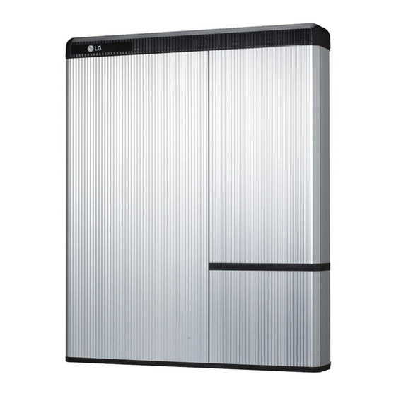
2 Product Introduction Technical data 2.1.1 Dimensions and weight RESU10H EVESPBO0100B0 Width 744 mm (29.3”) Height 907 mm (35.7”) Depth 206 mm (8.1”) Weight 97 kg (214 lbs) 907 mm 1) A battery pack’s weight (35.7”) varies slightly. 744 mm (29.3”) -
Page 12: Performance
Energy is measured under specific condition from LGC (0.3CCCV/0.3CC). 1) Value for Battery Cell Only(Depth of Discharge 95%). 2) LG Chem recommends 3kW for maximum battery lifetime. 3) Peak Current excludes repeated short duration(less than 10 sec. of current pattern). -
Page 13: Feature
Feature storag otov oltag oltag oltag Packaging specification Category Contents... -
Page 14: Installation
3 Installation Mechanical requirements 3.1.1 Unboxing the package 1. Cut the packing tape and open the carton. 2. Pull out other items. Take them out and check if any item is missing. See Package items on section 3.1.2... -
Page 15: Unboxing The Package
Installation 3. Remove the wall bracket guide pad & cushioning pad. 4. Remove the side pad. 5. Pull out the battery pack using handles and stand it up. (Lift handles are sold separately for this product.) CAUTION According to regional regulations, several people may be required for moving equipment. -
Page 16: Items In The Package
Installation 3.1.2 Items in the package These items are included in the package. Battery pack Wall bracket M6 wall mount Manual User Guide bolts (2EA) 3.1.3 Installation locations Required : There must be no highly flammable or explosive materials nearby. The ambient temperature should be within the range of 14 ~ 113°F (-10 ~ 45°C). -
Page 17: Clearance
3.1.4 Clearance 300mm (12") 300mm 300mm (12") (12") 600mm (24") Floor 3.1.5 Tools & safety gears required Tools ollo r er... - Page 18 Installation gear f It is recommended to wear the following safety gears when handling the battery pack. Insulated gloves Safety goggles Safety shoes NOTE RESU HV is heavy and challenging to lift. Lift handles are recommended.
-
Page 19: Mounting Bracket
Installation 3.1.6 Mounting bracket When installing the battery pack on a wall, make sure that the wall is capable of supporting the weight of the battery pack. To mount the battery pack on a wall, take the following steps : 1. -
Page 20: Appearance And Dimension
Installation 3.1.7 Appearance and dimension Appearance 907mm (35.7") 744mm (29.3") 206mm stic (8.1") 3.1.8 System clearance 300mm (12") Inverter 300mm (12") 600mm (24") Floor... -
Page 21: Installing The Battery Pack
Installation 3.1.9 Installing the battery pack CAUTION connecting the power cable to the battery pack. 1. Fix the lift handles to the hex-socket screws on the rear (marked position) of both left and right sides. 2. Mount the wall bracket to a wall. Tighten the screws, ensuring that they are horizontally driven into the wall. - Page 22 Installation 4. Tighten the two hex-socket screws enclosed and remove the lift handles. The nuts for these screws are welded to the battery pack chassis. Tighten to a torque of 5 N m using the M6 torque wrench. 5. Press the two buttons and pull the two latches (marked position) on the rear side of the wiring box cover (hinged door).
- Page 23 Installation 7. Loosen the screw (marked position), and remove the transparent protection cover. CAUTION If you lose or break a protection cover, that violates NEC Regulation. Transparent protection cover 8. Remove the cap on hole in the bottom side, and assemble the ¾" conduit plug.
-
Page 24: Cable Connection
Installation Cable connection 1. See 3.2.1. for Power Cable specifications a) Connect the ground wire to terminal 1. b) Connect the negative line of the power cable to terminal 2. c) Connect the positive line of the power cable to terminal 3. 2. - Page 25 Installation CAUTION Please must do the switch on & off operation at the middle side of SHT31 and Ex9BP combined. It’s forbidden to do the operation at the left or right edge side of combined body. Any wrong operation cause the products break off. 5.
-
Page 26: Auxiliary Power Switch And Spring Terminal Blocks
Installation 3.2.1 Auxiliary power switch and spring terminal blocks Auxiliary power switch Power terminal block Communication terminal block Auxiliary power switch SPG-Electronics Rocker Switch SPG-R36 2. Power terminal block Max cable length: 10m (35ft) Cable Type : 4~10 (8~12AWG) DC 600V insulatedz Pinning ( + ) Phoenix Contact... -
Page 27: Commissioning
4 Commissioning LED indicators The LED indicators on the front of the battery pack show its operational state as follows: LED Status Action Power on, Idle Charging Discharging Fault There are four LED indicators on the front of the battery packs to show its operating status. -
Page 28: Powering Up The Battery Pack
CAUTION If it stays o , indicates FAULT or fails to operate, do not use the battery pack and contact LG Chem (page 34) or your distributor. Shutting o the battery pack To shut down the battery pack, follow these steps : Turn o the inverter. -
Page 29: Troubleshooting
5 Troubleshooting Troubleshooting Check the indicators on the front to determine the state of the battery pack. A warning state is triggered when a condition, such as with voltage or temperature, is beyond design limitations. The battery pack’s BMS periodically reports its operating state to the inverter. -
Page 30: Post-Installation Check List
Troubleshooting 5.1.1 Post-Installation Check List 1. Visual check if the wiring matches with the installation manual. (3.2 Cable connection) 2. Both the Auxilliary Power Switch and Circuit Breaker are ON. 3. The battery "ON" LED is ON. The inverter power is ON. The inverter has the latest firmware. - Page 31 Troubleshooting If the battery LED is ON, but the battery is not charging or discharging 1. Update both the inverter and battery firmware version. Refer to the inverter's troubleshooting guide for instruction. 2. Check the inverter's setting for battery. Refer to the inverter's troubleshooting guide for the battery set-up instruction. 3.
-
Page 32: Uninstallation & Return
6 Uninstallation & Return Return/replacement instructions 6.1.1 Uninstallation from the wall 1. Switch OFF the Inverter before starting the uninstallation of the battery pack. 2. Press the two buttons and pull the two latches (marked position) on the rear. 3. Open the wiring box cover (about 2~10 degrees), and pull to remove it. - Page 33 Uninstallation & Return Check for voltage at power cable terminal. 7. Disconnect the communication cable from the communication port. 8. Disconnect the power cable from the terminal block. Disconnect the positive terminal (+) first, and next the negative terminal (−) finally ground terminal 9.