Table of Contents
Advertisement
Advertisement
Table of Contents
Troubleshooting

Related Manuals for Polaris 600 Fusion


Summary of Contents for Polaris 600 Fusion
- Page 3 Read, understand, and follow all of the instructions and safety precautions in this manual and on all product labels. Failure to follow the safety precautions could result in serious injury or death. PROPOSITION 65 WARNING Snowmobile engines discharge fuel and exhaust, which contain chemicals known to the State of California to cause cancer and birth defects or other reproductive harm, onto the snow on which they operate.
- Page 4 Polaris enthusiasts. Be sure to visit us online at www.polarisindustries.com for the latest news, new product introduc- tions, upcoming events, career opportunities and more. Here at Polaris we proudly produce an exciting line of utility and recre- ational products. • Snowmobiles •...
- Page 5 POLARIS and POLARIS THE WAY OUT are registered trademarks of Polaris Indus- tries Inc. RIDER SELECT is a trademark of Polaris Industries Inc. M-10 is a registered trademark of FAST Inc. Copyright 2005 Polaris Sales Inc. All information contained within this publication is based on the latest product information at the time of publication.
-
Page 6: Table Of Contents
Polaris Products..... . . 124 Troubleshooting ..... . . 125 Warranty . -
Page 7: Introduction
Remove the spare key and store it in a safe place. Your key can be duplicated only by mating a Polaris key blank with one of your existing keys, so if both keys are lost, the ignition switch must be replaced. -
Page 8: Preservation Of The Environment
Polaris snowmobiles are engineered to conform to these SAE standards. Our muffler systems are designed to reduce noise levels and must not be altered or removed. The sound of your snowmobile may not be wel- come to non-snowmobilers, so you have a responsibility to operate your snowmobile with concern for others. -
Page 9: Safety
SAFETY Operator Safety The following signal words and symbols appear throughout this manual and on your vehicle. Your safety is involved when these words and sym- bols are used. Become familiar with their meanings before reading the manual. The safety alert symbol, on your vehicle or in this manual, alerts you to the potential for injury. -
Page 10: Operator Safety
Always check major and vital safety components before every ride. All Polaris snowmobiles are designed and tested to provide safe operation when used as directed. Failure of critical machine components may result from operation with any modifications, especially those that increase speed or power. - Page 11 SAFETY Operator Safety Stay Clear of Track Your snowmobile is propelled by a revolving track that must be partially exposed for proper operation. WARNING Serious injuries may result if hands, feet, or clothing become entangled in the track. Be alert when riding, and remain properly seated to stay clear of the track.
-
Page 12: Riding Position
Operator Safety Riding Position Operating a snowmobile requires skill and balance for proper control. Rider positions may vary with experience and the features available on some snowmobiles, but under many conditions, the proper position is to be seated with both feet on the running boards and both hands on the handlebar grips for proper throttle, brake and steering control. -
Page 13: Survival Preparation
SAFETY Operator Safety Survival Preparation For your safety, always ride in a group of other snowmobilers. Always tell someone where you're going and how long you expect to be gone. If it isn't possible to ride with others, and you must travel into remote areas, always carry survival equipment that's appropriate to the condi- tions you may encounter. -
Page 14: Disabled Operators
Operators with cognitive or physical disabilities have an increased risk of loss of control, which could result in serious injury or death. Rider Capacity Your Polaris snowmobile is designed for a single rider only. Do not carry a passenger. Excessive Speed WARNING High speed driving, especially at night, could result in serious injury or death. -
Page 15: Driver Awareness
SAFETY Operator Safety Driver Awareness Slow down when traveling near poles, posts, or other obstacles. Be especially alert if you're snowmobiling after dark. Always be on the alert for wire fences. Single strands are especially dangerous, since there may be a great distance between posts. - Page 16 Operator Safety Avalanches Snowmobilers should always be properly trained and equipped before traveling in mountainous terrain: • Take an avalanche class • Travel with experienced people • Travel on designated trails • Make sure each person is equipped with a shovel, probe and avalanche beacon.
-
Page 17: Ice And Snow Build-Up
SAFETY Operator Safety Ice and Snow Build-up WARNING Ice and snow build-up may interfere with the steering of your machine, result- ing in serious injury or death. Keep the underhood area free of snow and ice. Before driving, manually turn the skis to the left and right to be sure ice and snow are not interfering with full left and right steering. -
Page 18: Driving Downhill
Operator Safety Driving Downhill When riding downhill, shift your weight to the rear of the machine and reduce your speed to a minimum. Apply just enough throttle to keep the clutch engaged, allowing the engine's compression to help slow the machine and keep it from rolling freely downhill. -
Page 19: Driving In Hilly Terrain
SAFETY Operator Safety Driving in Hilly Terrain WARNING Climbing a hill or crossing the face of a slope may result in loss of balance and machine roll-over, causing serious injury or death. Use caution and good judgement when driving in hilly terrain. Use extra caution when operating in hilly terrain. -
Page 20: Drive Belt
SAFETY Operator Safety Drive Belt Do not operate the engine with the drive belt removed. Any servicing that requires operation without a belt must be performed by your dealer. Operation of the engine with the belt removed may result in injury or damage to the engine. Intake Silencer Do not operate the engine with the intake silencer or filter removed. -
Page 21: Inadequate Snow Conditions
SAFETY Operator Safety Inadequate Snow Conditions WARNING Do not drive for prolonged periods on blacktop, gravel, or ice. Doing so could cause irreversible track damage and lead to serious injury. Since snow provides the only lubrication for the power slide suspension and, on liquid cooled models, cooling for the engine, adequate snow cover is a requirement for operation of your machine. -
Page 22: Driving Responsibly
Operator Safety Driving Responsibly Every snowmobile handles differently, and even the most docile condi- tions may become dangerous if operators drive improperly. If you're new to snowmobiling, acquaint yourself with the machine and with what it will and won't do under various conditions. Even seasoned driv- ers should spend some time getting the feel for a machine before attempting ambitious maneuvers. - Page 23 SAFETY Operator Safety Windchill/Temperature Charts The following information is provided to help you determine when tem- peratures become dangerous for riding. WIND CHILL CHART (_F) Estimated Wind Speed in MPH Calm Wind Speeds Little Danger Greater Than (For Properly 40 MPH Have clothed Person) Little Added Effect...
-
Page 24: Clutch Cover Warning
If any decal becomes illegible or comes off, contact your Polaris dealer to purchase a replacement. Replacement safety decals are provided by Polaris at no charge. -
Page 25: Track Warning
SAFETY Safety Decals and Locations Track Warning The track warning decal is on the rear of the tunnel: Stay clear of track. Do not sit on seat back. Entanglement with the track or a fall from seat back may result in severe injury or death. -
Page 26: Reverse Warning
Safety Decals and Locations Reverse Warning The reverse warning decal is located on the console below the wind- shield: WARNING Reverse operation, even at low speeds, can cause loss of control resulting in serious injury or death. To avoid loss of control, always: •... -
Page 27: Safety Decals And Locations
• To avoid serious injury or death, read and understand all warnings and the Owner's Manual before operation. If manual is missing, con- tact a Polaris dealer for a replacement. • This vehicle is capable of high speeds. Buried objects or uneven terrain can cause loss of control. -
Page 28: Features
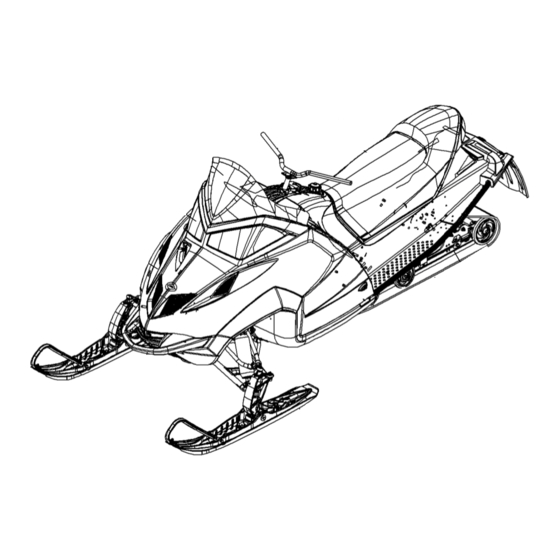
FEATURES 1. Hood 2. Headlight 3. Windshield 4. Handlebar 5. Seat 6. Snow Flap 7. Suspension 8. Track 9. Storage Compartment 10. Rear Bumper 11. Taillights 12. Nosepan 13. Front Bumper 14. Skis... -
Page 29: Features
FEATURES 1. Fuel Filler Cap 2. Ignition Switch 3. Brake Lever 4. RIDER SELECT 5. MFD Gauge 6. Headlight Adjuster 7. Engine Stop Switch 8. Throttle Control 9. Hood Hold Down Straps 10. Recoil Starter Handle 11. Headlight Dimmer Switch 12. -
Page 30: Features
RIDER SELECT Adjustable Steering System The RIDER SELECT adjustable steering system allows you to adjust the handlebar position to fit your style of riding. Setting Position Comfort 1, 2 Control 3, 4, 5 Attack 6, 7 WARNING Some aftermarket accessories (including windshields and cargo bags) may interfere with the handlebar. -
Page 31: Features
FEATURES RIDER SELECT Adjustable Steering System WARNING Attempting to adjust the handlebar position while the snowmobile is moving could result in loss of control and serious injury or death. Always stop the snowmobile before attempting to adjust the steering system. 1. -
Page 32: Fuel Valve
FEATURES Fuel Valve The fuel valve is located under the hood. Turn the fuel valve off when- ever the snowmobile is stored or parked. 1. Turn the valve clockwise to turn off the fuel supply. 2. Turn the valve counter-clock- wise to turn on the fuel supply. -
Page 33: Features
FEATURES Detonation Elimination Technology (D.E.T.) The DET system prevents damage to the engine from detonation while developing the maximum power of the engine safely. A detonation sen- sor monitors the engine and responds to detonation by automatically reducing the engine timing. This can result in decreased engine RPM and performance. -
Page 34: Features
Detonation Elimination Technology (D.E.T.) DET Troubleshooting Use this chart to determine causes and solutions for detonation. If none of these conditions exists and the sensor remains activated, see your Polaris dealer for diagnosis. Possible Cause Poor quality fuel Improper engine modifications... -
Page 35: Features
FEATURES Instrumentation MFD Component Identification Item 1 Analog Gauge 2 Digital Gauge 3 DET Indicator 4 Low Oil Indicator 5 High Temp Indicator 6 Brake Indicator 7 Reverse Indicator 8 High Beam Indicator Digital Display Identification Item 1 RPM or Speed Altitude (if equipped) Service Interval 2 Electrical System... -
Page 36: Features
Instrumentation MFD Settings With the engine running, use the MFD Control Switch to set the MFD display to your preference. The rocker switch (✪) has a MODE but- ton (top) and a SET button (bottom). Standard vs. Metric The MFD will display either stan- dard or metric units of measurement. -
Page 37: Features
FEATURES Instrumentation MFD Digital Display Programs Press the MODE button to cycle through the three MFD programs: Per- formance, Engine and History. Each program will remain in the display until another is selected. NOTE: The analog will always display either MPH or engine RPM (whichever setting is selected) regardless of the display pro- gram being viewed. -
Page 38: Features
FEATURES Instrumentation MFD Digital Display Programs Trip Settings Trip 1 and Trip 2 are odometers used to check fuel mileage or to keep track of distance traveled. 1. To reset a trip odometer to zero, enter the Trip 1 or Trip 2 display. 2. -
Page 39: Features
FEATURES Instrumentation MFD Digital Display Programs Performance Program Clock Setting 1. While in the CLOCK display, press and hold the SET button for five seconds. 2. When the hour starts flashing press the SET switch once to advance one hour, or press and hold the SET button to advance the hour once every 0.2 seconds. -
Page 40: Features
FEATURES Instrumentation MFD Digital Display Programs Engine Program The Engine Program automatically displays the engine coolant tempera- ture, engine hours, electrical system voltage level and fuel level. On machines equipped with altimeter sensor and ambient air temperature sensors, altitude and ambient air temperature will display as additional screens in the engine program. -
Page 41: Features
FEATURES Instrumentation MFD Digital Display Programs Engine Program Altitude (if equipped) The rider can calibrate the altimeter for current atmospheric conditions. Altimeter accuracy will be +/-300 ft. (91 m) after adjustment. NOTE: Press and hold the MODE switch for ten seconds to switch between stan- dard and metric units of measure- ment. -
Page 42: Features
Instrumentation MFD Digital Display Programs History Program The History Program automatically displays electrical system voltage level and fuel level. While in the History mode, press the SET button to view maximum vehicle speed, maximum engine rpm or the current service interval set- ting. -
Page 43: Features
FEATURES Instrumentation MFD Digital Display Programs Service Interval Reminder The gauge logs the number of engine hours between service reminders. When the logged hours reaches the designated service interval (set by the user), the gauge provides a reminder that service is due. "SErVCE" will flash in the odometer area and "ENG"... -
Page 44: Features
Instrumentation MFD Battery Replacement If the clock function of the MFD isn't working properly, replace the battery. Replacement batteries are available from your dealer. 1. Remove the plenum from the under- side of the hood. 2. Locate the black battery compart- ment. -
Page 45: Features
FEATURES Instrumentation MFD Battery Replacement 6. Install a new battery with fingers only. 7. Seal the end of the battery compartment using high strength double- sided tape between the two compartment halves or high strength single-sided tape around the outside of the compartment. 8. -
Page 46: The Perfect Fit
IQ Front Suspension Adjustments Independent Front Suspension (IFS) Break in the suspension for about 150 miles (240 km) before making any fine-tuning adjustments. Settings will vary from rider to rider, depending on rider weight, vehicle speed, riding style, and trail conditions. We recommend starting with factory settings and then customizing each adjustment individually to suit rider preference. -
Page 47: Front Shock Spring Preload
Shocks contain high-pressure nitro- gen gas. Use extreme caution when handling high-pressure service equip- ment. We recommend that this work be performed by a Polaris dealer. Front Springs The front springs can be changed if spring preload alone isn't sufficient and further adjustment is desired to control suspension stiffness. -
Page 48: Rear Suspension Adjustments
Refer to the suspension setup label on your snowmobile, or see your Polaris dealer for initial suspension setup information. Additional adjustments can be made after initial setup. Make adjustments to one area at a time so you can evaluate the change. For further assistance, see... -
Page 49: Suspension Performance Tips
Bogie wheel kits are available from your dealer. • Polaris offers track kits for improved flotation in deep snow. See your dealer for assistance. NOTE: Keep the suspension pivot points lubricated. This will reduce moisture and rust build-up and ensure proper function of the suspension components. - Page 50 IQ Rear Suspension Adjustments Initial Spring Preload Setting (Sag Method) To set up the IQ rear suspension tor- sion spring preload, measure the distance between the ground and rear bumper. This is measurement Take the first measurement with no rider and with the rear suspension at full extension.
-
Page 51: Torsion Spring Tension
Different rate torsion springs are available if a firmer ride is desired. See your dealer for more information. A - Soft Tension B - Medium Tension C - Firm Tension Rear Shocks Polaris Position Sensitive Shock There are no external adjustments on the Polaris position sensitive (PPS) shock. -
Page 52: Suspension Coupling
IQ Rear Suspension Adjustments Suspension Coupling On all Polaris snowmobile rear suspensions, there are two torque arms that control the movement of the rail beam. Prior to the advent of sus- pension coupling, these torque arms could move independently of each other. - Page 53 THE PERFECT FIT IQ Rear Suspension Adjustments Rear To Front Coupling and the Rear Rear Scissor Stop (RRSS) The rear rear scissor stop (RRSS) couples the movement of the rear torque arm with the front torque arm and limits the amount of indepen- dent movement between the rear torque and the front torque arm.
-
Page 54: Weight Transfer During Acceleration
IQ Rear Suspension Adjustments Weight Transfer During Acceleration The preferred method for controlling weight transfer during acceleration is by adjusting the rear rear scissor stop (RRSS). The factory setting is the best for most trail riding conditions. To decrease weight transfer under acceleration (for improved corner- ing), rotate the RRSS to a higher position with the scissor stop tool... - Page 55 THE PERFECT FIT FAST M-10 Rear Suspension Adjustments The M-10 suspension has been designed to be very sensitive to rider weight. Changes in rider weight of 25 lbs. (11 kg) or more might require appropriate changes in settings. The following information has been compiled to assist you in tuning your M-10 suspension to its maxi- mum potential and achieve the best possible ride.
- Page 56 THE PERFECT FIT FAST M-10 Rear Suspension Adjustments Static Sag and Ride Height Settings 3. Subtract Y from X and you will have the SAG setting (X - Y = sag setting. Example: 21 - 17 = 4). NOTE: The ideal amount of sag recommended for the FAST M-10 rear suspension is 3-4 inches (8-10 cm).
- Page 57 THE PERFECT FIT FAST M-10 Rear Suspension Adjustments Static Sag and Ride Height Settings FRA Position The FRA setting is the primary rear suspension adjustment. It will have the MOST effect on the rear suspension performance. To adjust the FRA: 1.
- Page 58 If FRA position alone does not allow the setup of the proper amount of sag, the center retainer of the rear track shock can be replaced with optional retainers to adjust the preload and change the sag. See your Polaris dealer for assistance. Retainer Insert Retainer Part...
- Page 59 THE PERFECT FIT FAST M-10 Rear Suspension Adjustments Ski Pressure Ski pressure is set at the factory to deliver the optimum balance between ride and handling. If a rider prefers more ski pressure for improved steering performance, adjustments can be made to the front limiter strap and front arm mount.
- Page 60 SAG height and reduce rear suspension travel. Initial M-10 Suspension Set-up Chart NOTE: The initial M-10 suspension set-up chart was not available at the time of printing. Please see your Polaris dealer. THE PERFECT FIT...
-
Page 61: Handlebar Position
THE PERFECT FIT Handlebar Adjustments Handlebar Position Use the RIDER SELECT feature to adjust handlebar position. See page Handlebar Angle Follow these steps to adjust handlebar angle at the handle- bar block. 1. Remove the handlebar cover (1) to expose the handlebar and the four adjuster block bolts (2). - Page 62 Accessories Polaris offers a wide range of accessories for your snowmobile to help make each ride more enjoyable. Use only Polaris parts and accessories on your Polaris snowmobile. Use of unapproved parts and accessories may result in: • Non-compliance with government/industry requirements •...
-
Page 63: Traction Products
Before equipping your machine with traction products, be aware of the laws in your area pertaining to the use of traction products. Use only Polaris traction products on your snowmobile. Track warran- ties are void if track damage or failure results from improper or exces- sive stud installation or the use of non-Polaris traction products. -
Page 64: Wear Strips
Traction Products nCarbide Skags A skag is a replaceable bar attached to the underside of the ski to assist in turning the snowmobile and to prevent ski wear caused by contact with roads and other bare terrain. Use carbide skags with studded tracks to help maintain proper vehicle steering and control. -
Page 65: Pre-Ride Inspections
PRE-RIDE INSPECTIONS Pre-Ride Checklist Inspect all items on the checklist for proper operation or condition before each use of the snowmobile. Procedures are outlined on the ref- erenced pages. Look for a checkmark (n) on the referenced pages to locate the pre-ride inspection items. Drive Belt Condition Steering System Recoil Rope... -
Page 66: Before Starting The Engine
Before Starting the Engine WARNING Worn, damaged, or malfunctioning components may cause serious injury or death. Before starting the engine, check all components to be sure of proper operation. Read and Understand Your Owner's Manual Read the Owner's Manual completely and refer to it often. The manual is your guide to safe and enjoyable snowmobiling experience. -
Page 67: Brake Lever Travel
PRE-RIDE INSPECTIONS Before Starting the Engine n Brakes Always check the following items for proper operation before starting the engine. Brake Lever Travel Squeeze the brake lever. It should move no closer to the handgrip than 1/2I (1.3 cm). A smaller distance indicates low brake fluid level or air in the hydraulic system. -
Page 68: Park Brake Lever Lock
Before Starting the Engine n Park Brake Lever Lock Use the park brake lever lock only when you want the machine to remain stationary; for example, when parked on an incline for a period of five minutes or less. 1. Brake Lever 2. -
Page 69: Steering System
PRE-RIDE INSPECTIONS Before Starting the Engine n Steering System WARNING Ice and snow build-up may interfere with the steering of your machine, result- ing in serious injury or death. Keep the underhood area free of snow and ice. Before driving, manually turn the skis to the left and right to be sure ice and snow are not interfering with full left and right steering. -
Page 70: Hood Latches
Recoil Rope Inspect the recoil rope and handle for excessive wear, and make sure the knot securing the rope inside the handle is secure. If excessive wear is found, see your Polaris dealer for replacement. -
Page 71: Start The Engine And Check
PRE-RIDE INSPECTIONS Start the Engine and Check Engine Stop Switch Check the auxiliary shut-off switch for proper operation. Push the switch down to stop the engine. Pull it up to allow restarting. Ignition Switch Make sure the engine stops when the ignition switch is turned to OFF. Tether Switch If your machine has a tether switch, remove the tether from the switch to make sure the engine stops immediately. -
Page 72: Operation
Starting the Engine WARNING Before starting the engine, always refer to all safety warnings pertaining to snowmobile operation. Never start your snowmobile without checking all components to be sure of proper operation. See Before Starting the Engine beginning on page 63. Starting a Cold Engine (Manual Start) Do not depress the throttle until the engine starts. -
Page 73: Starting A Warm Engine
Premix the first tank of fuel with one pint of Polaris injection oil for each five gal- lons of fuel. This, in addition to the lubrication supplied by the injection system, will assure proper engine break-in. -
Page 74: Oil Injection System
This snowmobile is equipped with a variable exhaust system (VES). Engine lubrication comes from oil added to the fuel and oil injection systems. Polaris recommends the use of VES II 2 Cycle Oil for this engine. See page 124 for the part numbers of Polaris products. -
Page 75: Track Warm-Up
OPERATION Track Warm-Up WARNING A loose track or flying debris could cause serious injury or death. Stand clear of the front of the machine and the moving track. Never hold the snowmobile up or stand behind it while warming up the track. Do not use excessive throt- tle during warm-up or when the track is free-hanging. - Page 76 Fuel WARNING Gasoline is highly flammable and explosive under certain conditions. • Always exercise extreme caution whenever handling gasoline. • Always refuel outdoors or in a well-ventilated area. • Always turn off the engine before refueling. • Do not overfill the tank. Do not fill the tank neck. •...
-
Page 77: Fuel Level
OPERATION Fuel For peak performance, Polaris recommends the use of 91 octane or higher fuel. Although 87 octane fuel is usable, some engine perfor- mance will be lost and fuel economy will decrease. Do not use fuel lower than 87 octane. -
Page 78: Low Oil Indicator Light
Always maintain a visible level of oil in the tank. If oil is not visible, continued operation may cause serious engine damage. See page 71 for oil recommendations. The Polaris oil cap on the oil bottle is vented to allow proper oil flow. See your Polaris dealer for recommended replacement parts. OPERATION... - Page 79 Either condition may be caused by improper carburetor adjustment. WARNING Improper carburetor adjustments may result in operator safety hazards as well as serious engine damage. Always have your Polaris dealer perform any carburetor adjustments.
-
Page 80: Jetting Guidelines
Carburetion Jetting Guidelines Changes in altitude and temperature affect air density, which is the amount of oxygen available for combustion. In low elevations and cold temperatures, the air has more oxygen. In higher elevations and higher temperatures, the air is less dense. The carburetors are calibrated for an altitude of 0-2000 ft. -
Page 81: Engine Stop Switch
OPERATION Engine Stop Switch Push down on the engine stop switch (✪) to ground out the ignition and stop the engine quickly. Pull the switch up to the ON position to allow restarting. Throttle Safety Switch The throttle safety switch is designed to stop the engine whenever all pressure is removed from the throttle lever and the throttle cable or valves do not return to the normal closed position. -
Page 82: Throttle Lever
When these switches are disconnected, the ignition key switch must be used to shut off the engine. DO NOT continue to operate the machine with the throttle safety switch disconnected. Return the machine to an authorized Polaris dealer for service as soon as possible. OPERATION... - Page 83 OPERATION Emergency Stopping The following chart lists methods for stopping the snowmobile in the event of an emergency. See page 78 for more information about the engine stop switch and throttle safety switch. SYSTEM Ignition Switch Brake Choke Engine Stop Switch Throttle Safety Switch Tether Switch (Option) WHAT IT DOES...
-
Page 84: Emergency Starting
Emergency Starting If the recoil starter system fails, an emergency start strap is provided in the tool kit. 1. Open the hood. 2. Remove the left side panel. 3. Using the belt removal tool, follow the directions on the air box to relieve belt tension. 4. - Page 85 OPERATION Electronic Reverse (PERCt) Electronic reverse will activate only if the engine RPM is below 4000. WARNING Improper reverse operation, even at low speeds, may cause loss of control, resulting in serious injury or death. Damage will occur to the chaincase or transmission if shifting is attempted when the engine is operating above idle speed.
-
Page 86: Daily Storage
Daily Storage At the end of each ride, park the snowmo- bile on a level surface and support it at the rear with an appropriate track stand. The track should be suspended approximately 4I (10 cm) off the ground. Remove the key and cover the machine. Towing WARNING Objects towed with a rope have no braking power and can easily collide with... -
Page 87: Maintenance
Personal safety is critical when attempting to service or make adjust- ments to your snowmobile. If you're not familiar with safe service or adjustment procedures and the use of tools, or if you don't feel comfort- able performing these tasks yourself, contact an authorized Polaris dealer for service. CAUTION Hot components can cause damage to plastic. - Page 88 The following chart is a guide based on average riding conditions. You may need to increase frequency based on riding conditions. When inspection reveals the need for replacement parts, always use genuine Polaris parts, available from your Polaris dealer. Item Clutch Alignment Offset...
- Page 89 MAINTENANCE Periodic Maintenance Interval Table Item Hose Routing Hose Condition Fluid Leaks Brake Pads Brake Disc Parking Brakes Brake System Brake Fluid Pilot Air Screws Carburetor (synchronize) Idle RPM Throttle Lever Oil Pump Lever (synchronize) Throttle Cable Choke Cable Choke Vent Lines Throttle Position Sensor...
- Page 90 Periodic Maintenance Interval Table Item Ski Toe Alignment Suspension Mounting Bolts Steering Fasteners Rear Suspension Fas- teners Suspension Shock Oil Cooling Fins and Shroud Drive Shaft Bearing Jackshaft Bearings Skags (Wear Bars) Ski Saddle/Spindle Bolts Drive Chain Tension Hood Latches Rear Wheel Idler Bolts Idler Bolt Jam Nut Rear Suspension Pivot...
-
Page 91: Front Suspension
The front suspension and steering components do not require lubrica- tion. Rear Suspension Lubricate the suspension pivot shafts with Polaris Premium All Season Grease at 500 miles (800 km) initially, every 1000 miles (1600 km) after that, and before off-season storage each year. Lack of lubrication will adversely affect your ride and the life of the suspension. -
Page 92: Throttle Cable
MAINTENANCE Lubrication Driveshaft Bearing ✪ Inject grease into the fitting on the speedometer sensor housing until grease purges from the seal on the inside of the tunnel. This should take approximately two pumps. Do not use more than four pumps. Throttle Cable Lubricate the throttle cable lightly with grease or oil. -
Page 93: Chaincase Oil
500 miles (800 km), then every 1000 miles (1600 km) or seasonally. Polaris recommends the use of Polaris Synthetic Chaincase Lube. See page 124 for the part numbers of Polaris prod- ucts. Oil Check 1. Position the vehicle on a level sur- face. - Page 94 Lubrication Chaincase Oil Oil Change 1. Position the vehicle on a level surface. 2. Remove the drain plug (4) and drain the oil into a drain pan. Allow the oil to drain completely. 3. Install a new sealing washer on the drain plug.
-
Page 95: General Maintenance
MAINTENANCE General Maintenance Spark Plugs A new engine can cause temporary spark plug fouling due to the preser- vative added during the assembly process. Avoid prolonged idle speeds, which cause plug fouling and carbonization. Refer to your Owner's Manual Supplement for the specific spark plug to be used in your machine. -
Page 96: Spark Plug Condition
General Maintenance Spark Plug Condition Spark plug condition is indicative of engine operation. The spark plug firing end condition should be read after the engine has been warmed up and the vehicle has been driven at higher speeds. Immediately check the spark plug for correct color. -
Page 97: Oil Filter
MAINTENANCE General Maintenance Spark Plug Removal and Replacement 1. Remove the spark plug cap. 2. Using the special wrench provided in the tool pouch, rotate the spark plug counterclockwise to remove. 3. Reverse the procedure for spark plug installation. 4. Torque to 18-22 ft. lbs. (24-30 Nm). 5. -
Page 98: Intake Filters
All fuel pump service must be performed by an authorized Polaris dealer. Do not attempt to service the fuel pump. Fuel Filter/Fuel Lines See your Polaris dealer for replacement of the in-tank fuel filter every 1000 miles (or annually). Inspect the fuel lines regularly for signs of deterioration or damage. -
Page 99: Carburetor Adjustments
CAUTION Operating the snowmobile with incorrect jetting can result in serious engine damage. Have your Polaris dealer perform all carburetor adjustments to ensure all adjustments are done correctly. Carburetor Adjustments The frequency at which the carburetors are synchronized or balanced is important. -
Page 100: Cleaning Procedure
General Maintenance Carburetor Water/Sediment Trap Most Polaris snowmobiles contain patented carburetor bowl water/sedi- ment traps located at the bottom of each carburetor. The trap, consisting of a hose with a plug, should be drained about every 1000 miles (1600 km) and inspected for contamination. -
Page 101: Coolant Level
Use Premium 60/40 anti-freeze coolant, which is already premixed and ready to use. Do not dilute with water. Never exceed a 60% antifreeze/ 40% water mixture. See page 124 for Polaris products. NOTE: Never add tap water to the cooling system. Minerals cause deposits and may react adversely with the metals in the engine and cooling system. -
Page 102: Flushing The Cooling System
This service must be performed when the engine is cold. Ask your Polaris dealer to check the coolant when he performs the fall tune-up on your snowmobile. -
Page 103: Bleeding The Cooling System
MAINTENANCE General Maintenance Bleeding the Cooling System WARNING Steam and hot liquids will cause serious burns to your skin. Never bleed the cooling system or remove the pressure cap when the engine is warm or hot. Use of a non-standard pressure cap will not allow the recovery system to function properly. -
Page 104: Exhaust System
General Maintenance Exhaust System Check the exhaust system for wear or damage at approximately 2000 miles (3200 km). To inspect, allow the engine and exhaust system to cool completely. Open the hood and inspect the muffler and pipes for cracks or damage. Check for weak or missing retaining springs or damper/support grommets. -
Page 105: Drive Chain Tension
MAINTENANCE General Maintenance Drive Chain Tension Check drive chain tension weekly and before each long trip. To obtain correct chain tension: 1. Rotate the driven clutch counter- clockwise to move all chain slack to the tensioner side. Lock the brake lever lock, or have an assistant hold the brake lever firmly. -
Page 106: Hydraulic Brake Inspection
3. Brake Pad Material (Replace when thickness is less than 1/16I/1.5 mm). Excessive Lever Travel Hydraulic brakes are self- adjusting, but if excessive brake pad clearance develops, bring the machine to an autho- rized Polaris dealer for inspec- tion and adjustment. MAINTENANCE... -
Page 107: Brake Fluid
If the fluid is sufficient, the sight glass will be black. If the sight glass is any color other than black, add brake fluid. Replace brake fluid at least every two years with Polaris DOT 4 high temperature brake fluid. See page 124 for the part numbers of Polaris products. -
Page 108: Bleeding The Hydraulic Brake System
General Maintenance Bleeding the Hydraulic Brake System Air in the hydraulic brake system will cause spongy brake lever action. Bleed the system before operating the snowmobile. WARNING Operating the vehicle with a spongy brake lever can result in loss of brakes, which could cause an accident and lead to serious injury or death. -
Page 109: Headlight Bulb Removal
MAINTENANCE General Maintenance NOTE: Do not touch a halogen bulb with bare fingers. Oil from skin leaves a residue, causing a hot spot that will shorten the life of the lamp. If fingers do touch the bulb, clean it with an alcohol- moistened towel. - Page 110 General Maintenance Taillight/Brakelight Replacement 1. Open the rear storage compart- ment. 2. Reach into the compartment and locate the socket assembly above the door opening. 3. Turn the socket counterclockwise 1/4 turn. 4. Carefully pull the socket assembly away from the taillight. 5.
-
Page 111: Clutch System
Polaris dealer. Any unauthorized modifications to clutches, such as adding or removing weights, will void the warranty. CAUTION The bushings in the weights and rollers of Polaris clutches are made of a material that may be damaged if lubricated. Do not lubricate clutch bushings. Clutch Alignment Offset Clutch alignment offset is important for maintaining optimum perfor- mance. -
Page 112: Drive Belt Condition
General Maintenance n Drive Belt Condition Periodically check the condition and tension of the drive belt, and always carry a spare. Inspect the belt for signs of excessive wear: frayed edges, missing cogs, cracks and excessive looseness. Replace the belt if any of these conditions exist. -
Page 113: Drive Belt Installation
Drive Belt Belt width and length must match the center distance of the clutches and sheave width of the drive clutch. Polaris recommends the use of O.E.M. belts. Other belts may match the dimensions, but can drastically change the shift pattern, resulting in poor performance. -
Page 114: Drive Belt Deflection
General Maintenance n Drive Belt Deflection Measure belt deflection with both clutches at rest and in their full neutral position. Place a straight edge (1) on the belt and apply downward pres- sure while measuring at point 2. This measurement should be 1 1/4I (3.2 cm). -
Page 115: Tool Kit
A tool kit is included with each machine for emergency and routine maintenance. Always keep the tool kit with the snowmobile. Fall Tune-Up For maximum performance, arrange for a fall service tune-up with your Polaris dealer. His experienced and trained service technician will keep your machine in peak operating condition. -
Page 116: Track Inspection
Track Maintenance Track Inspection WARNING Broken track rods can cause a rotating track to come off the machine, which could cause serious injury or death. Never operate with a damaged track. Never rotate a damaged track under power. 1. Using a hoist, safely lift and support the rear of the snow- mobile off the ground. -
Page 117: Track Tension
MAINTENANCE Track Maintenance WARNING Moving parts can cut and crush body parts. When performing the checks and adjustments recommended on the following pages, stay clear of all mov- ing parts. Never perform track measurement or adjustments with the engine running. Track Tension Track adjustment is critical for proper handling. - Page 118 Track Maintenance Track Tension 4. Check for specified slack between the wear surface of the track clip and the plastic slider. Refer to the Track Tension Data Chart on page 114. If the track needs adjustment: 5. Loosen the rear idler shaft bolt. 6.
-
Page 119: Track Alignment
MAINTENANCE Track Maintenance n Track Alignment Periodically check that the track is centered and running evenly on the slide rails. Misalignment will cause excessive wear to the track and slide rail. 1. Safely support the rear of the machine with the track off the ground. 2. - Page 120 MAINTENANCE Steering System Steering Inspection and Adjustment Each week, or before a long ride, check all steering system fasteners and tighten if necessary. ✪ ✪ ✪ ✪ ✪...
-
Page 121: Ski Alignment
Improper ski alignment or adjustment may cause loss of steering control, resulting in serious injury or death. Do not attempt to change the ski align- ment or camber adjustment. See your Polaris dealer. With the handlebars in a straight ahead position, and with vehicle weight compressing the suspension, measure from the straight edge of the skis at the center of the ski mounting bolt. -
Page 122: Ski Skags
Steering System n Ski Skags WARNING Worn skis and/or skags will adversely affect handling. Loss of vehicle control may result, causing serious injury or death. See your dealer's studding chart for recommended skags. If you install longer or more aggressive carbide skags than the original equipment, it may also be necessary to add track studs to maintain proper vehicle control while turning on hard-packed snow or ice. -
Page 123: Rail Slide Wear
MAINTENANCE Steering System n Rail Slide Wear Measure slide thickness at several points along the rail. Have your dealer replace the slide when it's worn down to the top of the wear limit indicator groove (✪). Do not operate the snowmobile if slide thickness measures less than 7/16I (1.1 cm). -
Page 124: Cleaning And Preservation
Extended Storage Off-season or extended storage of your snowmobile requires preventive measures to aid against deterioration and to prolong the useful life of many components. See page 124 for the part numbers of Polaris prod- ucts. Cleaning and Preservation Proper storage starts with cleaning, washing, and waxing the hood, chassis, and plastic parts. -
Page 125: Clutch And Drive System
MAINTENANCE Extended Storage Bearings Grease the jackshaft and drive shaft clutch side bearings with Polaris Premium All-Season Grease or a similar high quality grease to prevent corrosion. Clutch and Drive System Remove the drive belt and store in a cool dry location. Do not lubricate clutch components, except the driven clutch shaft bushing as outlined in the Master Repair Manual. -
Page 126: Electrical Connections
Extended Storage Electrical Connections Replace worn or frayed electrical wire and connectors. Be sure wiring harness is properly secured away from sharp edges, steering linkage, moving parts, and hot exhaust parts. Track and Suspension Moderate track tension should be maintained during summer storage. -
Page 127: Polaris Products
POLARIS PRODUCTS Part No. 2870791 Fogging Oil (12 oz. Aerosol) 2871098 Premium 2-Cycle Engine Oil (qt.) 2871097 Premium 2-Cycle Engine Oil (gal.) 2871240 Premium 2-Cycle Engine Oil (2.5 gal.) 2871721 Premium Gold Synthetic 2-Cycle Engine Oil (qt.) 2871722 Premium Gold Synthetic 2-Cycle Engine Oil (gal.) 2872347 Premium Gold Synthetic 2-Cycle Engine Oil (2.5 gal.) -
Page 128: Troubleshooting
Engine Troubleshooting Unless you have experience and training in two-cycle engine repair, see your dealer if technical problems arise. Problem Probable Cause Solution Erratic engine oper- Drive clutch binding ating RPM during Driven clutch mal- acceleration or load function variations Harsh drive clutch Drive belt worn or engagement... - Page 129 TROUBLESHOOTING Engine Troubleshooting Problem Probable Cause Solution Noise in drive sys- Broken drive clutch components Bearing failure/ chaincase, jackshaft, or front drive shaft Drive belt surface flat spots Drive chain loose Drive chain worn, sprocket teeth bro- Poor low RPM per- Worn drive belt formance Excessive belt/...
- Page 130 Engine Troubleshooting Problem Probable Cause Solution Engine turns but fails Faulty ignition to start No fuel to engine Poor engine com- pression Engine lacks power Fouled or defective spark plug(s) Fuel filter (loss of high RPM power) Incorrect clutching Carburetor and fuel pump Engine continually Faulty plug(s)
- Page 131 TROUBLESHOOTING IQ Suspension Troubleshooting Problem Solution Rear suspension bot- • Adjust torsion spring preload to achieve proper static sag toms too easily • Change torsion spring to stiffer optional spring (see your • Revalve rear track shock (see your dealer). Rides too stiff in rear •...
- Page 132 M-10 Suspension Troubleshooting Problem Solution Rear suspension bot- • Increase FRA position (see setup decal under hood for ini- toms too easily • Install appropriate optional center retainer on rear track • Increase front track shock coil spring preload. • Revalve rear track shock compression damping (see your •...
-
Page 133: Drive Belt Troubleshooting
TROUBLESHOOTING Drive Belt Troubleshooting Causes Driving at low RPM Insufficient warm-up Towing at low RPM Riding with high RPM and slow speed (8000 RPM/10 MPH) Ice and snow build-up between track and tunnel Poor engine performance Loading machines onto trailers Clutch malfunction Slow, easy clutch engage- ment... -
Page 134: Warranty
Service and Warranty Information Obtaining Service and Warranty Assistance Read and understand the service data and the Polaris warranty information con- tained in this manual. Contact your Polaris dealer for replacement parts, ser- vice or warranty. Your dealer receives frequent updates on changes, modifications and tips on snowmobile maintenance, which may supersede information contained in this manual. - Page 135 Polaris warranty will provide all dealerships with a monthly updated list of all stolen units to further monitor thefts. Polaris warranty will aid in notifying the proper owner when a unit is recovered.
-
Page 136: Limited Warranty
WARRANTY Limited Warranty Polaris Sales Inc., 2100 Highway 55, Medina, MN 55340, provides a ONE YEAR LIM- ITED WARRANTY on all components of the Polaris snowmobile against defects in material or workmanship. This warranty covers the parts and labor charges for repair or replacement of defective parts that are covered by this warranty. -
Page 137: Engine Oil
How to Obtain Warranty Service If your snowmobile requires warranty service, you must take it to a Polaris dealer autho- rized to repair Polaris snowmobiles. When requesting warranty service you must present your copy of the Warranty Registration form to the dealer. (The cost of transpor- tation to and from the dealer is YOUR responsibility). - Page 138 In order to qualify for warranty, the product must have been properly set up and tested by a Polaris Dealer (if applicable). Failure of any dealer to perform the required vehicle Pre-Delivery Inspection, perform all applicable service bulletins and have the consumer sign the PDI form prior to delivery may void the warranty.
- Page 139 • Failures caused due to improper adjustments. • Failure due to unauthorized service. • Failures due to lack of service as required in the owner's manual or Polaris updates. This includes off-season storage as listed in the owner's manual. • Failure due to use of unauthorized parts or modifications.
- Page 140 If Purchased From A Private Party: If you purchase a Polaris product from a private citizen outside of the country in which the vehicle was originally purchased, all warranty coverage will be denied.
-
Page 141: Maintenance Log
MAINTENANCE LOG Present this section of your manual to your dealer each time your snow- mobile is serviced. This will provide you and future owners with an accurate log of maintenance and services performed on the snowmobile. DATE MILES TECHNICIAN (KM) 150 mi. - Page 142 MAINTENANCE LOG DATE MILES TECHNICIAN SERVICE PERFORMED / COMMENTS (KM)
-
Page 143: Index
INDEX Accessories ....59 Adjustable Headlights ..29 Adjustable Steering System..27-28 Air Pollution . - Page 144 Park Brake Lever Lock ..65 POLARIS PRODUCTS ..124 Pre-Ride Checklist ... . . 62 PRE-RIDE INSPECTIONS .
- Page 145 INDEX Storage, Daily ....83 Storage, Extended ..121-123 Studs ..... . . 60 Survival Preparation .