Advertisement
CC1N7696en
20.04.2016
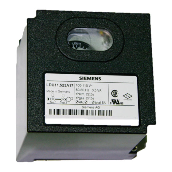
VALVEGYR®
Valve Proving System for
automatic Shutoff Valves
The LDU11... valve proving system is designed for use with shutoff valves in con-
nection with gas burners and gas appliances. In the event of inadmissible leakage,
the system prevents the burner from starting up.
The LDU11... system conforms to the requirements of EN1643 covering automatic
shutoff valves for use with gas burners and gas appliances to EN161.
The LDU11... and this Data Sheet are intended for use by OEMs which integrate the
valve proving system in their products.
Building Technologies Division
7
696
LDU11...
Advertisement
Table of Contents

Related Manuals for Siemens VALVEGYR LDU11.323A17


Summary of Contents for Siemens VALVEGYR LDU11.323A17
- Page 1 VALVEGYR® LDU11... Valve Proving System for automatic Shutoff Valves The LDU11... valve proving system is designed for use with shutoff valves in con- nection with gas burners and gas appliances. In the event of inadmissible leakage, the system prevents the burner from starting up. The LDU11...
- Page 2 The LDU11... is designed for automatic gas valve proving (leakage test) based on the pressure proving principle. It is for use on gas-fired combustion plant with or without vent pipe to atmosphere. In the case of plants with no vent pipe where EN standards apply, the notes given in «Connection examples without vent pipe to atmosphere»...
- Page 3 Installation notes Live and neutral conductors must not be interchanged Standards and certificates Applied directives: Low-voltage directive 2014/35/EC Directive for gas-fired appliances 2009/142/EC Directive for pressure devices 97/23/EC and 2014/68/EC (2016-07-16) Electromagnetic compatibility EMC (im- 2014/30/EC munity) *) *) The compliance with EMC emission requirements must be checked after the valve monitoring system is...
- Page 4 Life cycle LDU11... has a designed lifetime* of 250,000 burner startup cycles which, under normal operating conditions in heating mode, correspond to approx. 10 years of usage (starting from the production date given on the type field). This lifetime is based on the endurance tests specified in standard EN298 and the table containing the relevant test documenta- tion as published by the European Association of Component Manufacturers (Afecor) (www.afecor.org).
- Page 5 Mechanical design Valve proving system Plug-in design LDU11... Exchangeable unit fuse (including spare fuse) Housing Made of impact-proof and heat-resistant black plastic Lockout reset button with viewing window showing: – The fault signal lamp – The lockout indication - Coupled to the program spindle - With transparent lockout reset button - Easy-to-remember symbols indicating the type of fault and the time lockout occurred...
- Page 6 Technical data General unit data Mains voltage LDU11... LDU11.323A27 AC 220 V –15 %...AC 240 V +10 % LDU11.323A17 AC 100 V –15 %...AC 110 V +10 % LDU11.523A27 ¹) AC 220 V –15 %...AC 240 V +10 % LDU11.523A17 ¹) AC 100 V –15 %...AC 110 V +10 % ¹) Valve opening times do not conform to EN 1643...
- Page 7 Function During the first phase of the valve proving test called «Test1», atmospheric pressure must exist in the length of pipe between the valves to be tested. In plants with a vent pipe to atmosphere, atmospheric pressure is available if the valve proving test is made prior to or during the prepurge time.
- Page 8 Program and lockout indicator In the event of lockout, the programming mechanism stops and thus the position indicator fitted to the spindle of the mechanism. The symbol that stops above the reading mark indicates the test phase during which lockout occurred and also gives the number of programming steps completed from the start of this test phase (1 step = 2.5 seconds).
- Page 9 Calculation of the leakage rate escaping from a length of pipe ) x V x 3600 Leck Test Legend in dm³/h Permissible leakage rate in dm³ per hour or liters per hour leck in mbar Overpressure in pipe section between the valves to be tested, at the beginning of the test phase in mbar Overpressure set on pressure switch «DW»...
- Page 10 Connection diagram 7696a15/0204 12 19 23 20 22 21 XIII Atm. VIII LDU11 Legend Alarm signal for «leaking valve» Working relay with contacts (ar...) Unit fuse (built-in) Lockout relay with contacts (br...) Pressure switch for valve proving test (does not replace the gas pressure switch used to signal lack of gas) Lockout reset button Remote lockout reset button Gas pressure switch (for lack of gas)
- Page 11 Sequence diagram VIII XIII Output terminals controlled by the Test1 Test2 control unit or electrically connected Program indication 7696b01e/0601 Legend 22.1 s First test phase with atmospheric pressure 27 s Second test phase with gas pressure For LDU11.323... 2.5 s Filling the test space 2.5 s Evacuating the test space...
- Page 12 Connection examples with vent pipe to atmosphere using burner controls type LGB2..., LGB3... / LGB4... / LMG2... For other connections, refer to the connection diagram of the relevant burner control. Valve proving test prior to burner startup Valve proving test following immediately the controlled shutdown 7696a06/0703 7696a05/0403...
- Page 13 Connection examples with vent pipe to atmosphere using burner controls type LFE..., LFL... or LGK..., or the control unit LEC... For other connections, refer to the connection diagram of the relevant burner control. Check just prior to burner startup Check during the prepurge time (min. 60 seconds) Expanding flame burner or interrupted pilot burner Expanding flame burner or interrupted pilot burner 7696a07/0401...
- Page 14 Connection examples without vent pipe to atmosphere (for applications not covered by EN676) using burner controls type LFE..., LFL... or LGK..., or the control unit LEC... Check following immediately the controlled shutdown in plants without vent pipe. Valve (A) or valve (A1) remains open after the controlled shutdown until the start of the first test phase is reached in order to evacuate the test space and to burn off the gas in the combustion chamber during the afterburn time.
- Page 15 Connection examples without vent pipe to atmosphere using burner controls type LGB2... / LGB3... / LGB4... / LMG2... For other connections, refer to the connection diagram of the relevant burner control. Check prior to burner startup Check following immediately the controlled shutdown 7696a13/0403 7696a14/0703 LGB2.../3.../4.../LMG2...
- Page 16 Connection examples without vent pipe to atmosphere using burner controls type LFE..., LFL... or LGK..., or the control unit LEC... For other connections, refer to the connection diagram of the relevant burner control. Check just prior to burner startup Check during the prepurge time (min. 60 seconds) Expanding flame burner or interrupted pilot burner Expanding flame burner or interrupted pilot burner 7696a24/0401...
- Page 17 Connection examples without vent pipe to atmosphere using burner controls type LFE..., LFL... or LGK..., or control unit LEC... and actuator SKP7... with expanding flame burners For other connections, refer to the connection diagram of the relevant burner control Check just prior to burner startup Check during the prepurge time (min.
- Page 18 Connection examples without vent pipe to atmosphere using burner controls type LME21.xxxC... / LME22.xxxC... with expanding flame burners For other connections, refer to the connection diagram of the relevant burner control. LME22.xxxC... / LME22.xxxC... with LDU11... valve proving Before startup of burner ...
- Page 19 Connection examples with vent pipe to atmosphere using burner controls type LME21.xxxC... / LME22.xxxC... with expanding flame burners For other connections, refer to the connection diagram of the relevant burner control. LME22.xxxC... / LME22.xxxC... with LDU11... valve proving Valve supervision before startup of burner ...
- Page 20 Legend A, A1, A2 Gas valves controlled to evacuate the test space AGK25 PTC resistor Alarm signal for «leaking valve» ar... Contacts (operating relay) Gas valve controlled to fill the test space Vent valve, normally open; closed during valve proving test from the be- ginning of «Test1»...
- Page 21 Dimensions Dimensions in mm LDU11... Plug-in base AGM11 / AGM11.1 7696m04/0305 27,5 27,5 2016 Siemens AG Building Technologies Division, Berliner Ring 23, D-76437 Rastatt Subject to change! 21/21 Building Technologies Division CC1N7696en 20.04.2016...