Table of Contents
Advertisement
Advertisement
Table of Contents

Related Manuals for Motorola MOSCAD-M


Summary of Contents for Motorola MOSCAD-M
- Page 1 ™ MOSCAD-M Remote Terminal Unit Owner’s Manual 68P02961C50-O...
-
Page 2: Table Of Contents
NSTALLATION OF ACKUP ATTERIES ......................... 10 ISCELLANEOUS Open the Case Door..........................10 Close the Case Door ..........................10 Antenna Placement ..........................10 Fixed Site Antennas ..........................10 THE MOSCAD-M UNIT......................11 ..........................11 VERVIEW ......................12 OMMUNICATION ORTS ..........................12 ONNECTORS ....................... 12 ONTROLS AND... - Page 3 Contents LED Control............................13 System Software Downloading ......................13 CPU Reset............................13 LED D ......................14 ISPLAY NDICATIONS CPU Page LED Functions........................14 IO1 Page LED Functions........................15 IO2 Page LED Functions........................17 IO3 Page LED Functions........................18 AO Page LED Functions ........................19 User Page LED Functions ........................20 )........................
- Page 4 Contents APPENDIX B: MODELS AND ACCESSORIES ..............39 ............................ 39 ENERAL MOSCAD-M GP140/328/HT750/ PRO5150 R ......41 NSTALLATION OF WITH ADIO MOSCAD-M I GP140/GP328/HT750/ PRO5150 R ....42 NSTALLATION IT FOR ADIOS MOSCAD-M D ..................42 EBUG ARDWARE MOSCAD-M Board..........................42 Debug Setup ............................43...
-
Page 5: Introduction
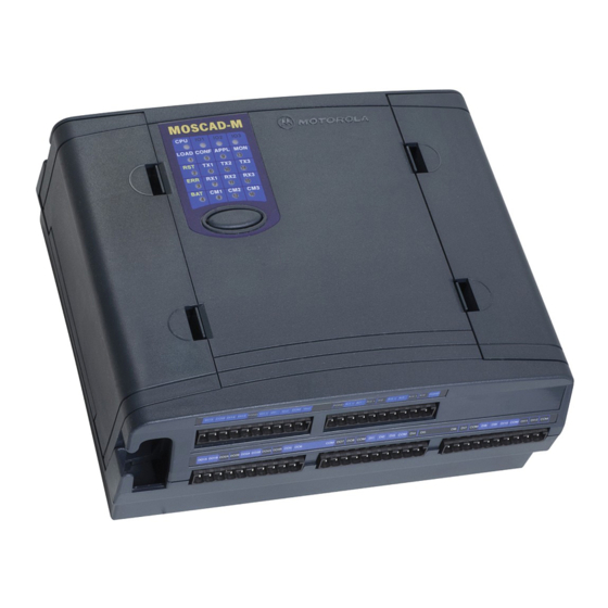
Figure 1 provides a general view of the MOSCAD-M RTU. The MOSCAD-M RTU is enclosed in an indoor plastic case and is intended for outdoor base station use. The installer must make sure that the installation meets the requirements of the standard and protects the unit from weather hazards. -
Page 6: Hardware Options
Variety of external radios (GP140/328, HT750, PRO5150) For details on the available external radio models, and their connection to the RTU, see Appendix B. I/O Configurations Different models of the MOSCAD-M RTU have slightly different I/O configurations. Models with basic I/O configuration: • 12 Digital Input •... -
Page 7: Installation
INSTALLATION General MOSCAD-M SAFETY SUMMARY The MOSCAD-M should be installed by qualified and authorized technicians. If the installation involves high-voltage connections, technicians must be specifically qualified to handle high voltage. This equipment was tested with cables 3 meters in length. If longer... -
Page 8: Wall Mounting With Screws
The unit can be installed on screws or on DIN rail mounting. Before installing the MOSCAD-M RTU, verify that there is sufficient space around the unit. Allow 20 cm (7.87") from the bottom of the box for the TB connectors. When an RF connector is attached (internal radio models), allow for an extra 10 cm (4"): 2.02 cm (.8") from the top of the box for the RF... -
Page 9: Wall Mounting On Din Rail
Installation of MOSCAD M – Screw Mount It is also possible to attach the MOSCAD-M to the wall using the small screw hole at the bottom of case, though this requires dismantling the RTU, which is generally discouraged. Consult Motorola service personnel before opening the MOSCAD-M casing. To mount the RTU: 1. - Page 10 Installation Figure 4 DIN Rail Attachment SNAP Figure 5 DIN Rail Attachment-Foot Element Snap-in (Enlarged) 2. Press the unit onto the DIN rail, using both universal foot elements. The elements can be used on DIN rail 35 mm and G rails. (See Figure 6). Figure 6 MOSCAD Mounted on DIN Rail...
-
Page 11: Connections
Installation Connections Verify that all power and ground connections are made in accordance with local standards. Ground Connection Connect the grounding cable directly to the protective grounding pins 9 and 10 (PGND) in the main power-in connector (see TB1 in Figure 9). Power Connections The unit can be connected directly to a 9-30V DC source through the main Power-In connector (see Figure 9) where Pin #1 is + (positive) and Pin #2 is –... -
Page 12: Line Communication Connection
Installation If the external radio is connected to an outside power supply, first power on the unit, and then power on the radio. The auxiliary power supply (maximum 2A) can be changed to 6V, 6.5V, 7.5V, 8V, 9V or 9.6V DC by changing the setting of the P11 jumper located on the Main board. -
Page 13: Installation Of Backup Batteries
Installation Installation of Backup Batteries The backup battery should not be installed before the unit is connected to the main power supply. This may cause the battery to drain. 1. Place 3 “C” size alkaline batteries into the carton cylinder, each in the same direction, as shown in Figure 7 below. -
Page 14: Miscellaneous
An antenna placed on top of the plastic housing produces strong electromagnetic fields that could be harmful to the electronics of the MOSCAD-M RTU and to people in the vicinity. Fixed Site Antennas The antenna installation must comply with the following requirements in order to assure optimal performance and make sure human exposure to radio frequency electromagnetic energy is within the guidelines set forth by the local regulations. -
Page 15: The Moscad-M Unit
THE MOSCAD-M UNIT Overview The MOSCAD-M RTU (shown below) contains power connections, line communication ports, internal/external radio interfaces, radio modems and I/Os. Figure 9 MOSCAD Unit... -
Page 16: Communication Ports
Ports 1A and 1B cannot work simultaneously. Port 3 cannot be used when an internal radio is installed. Connectors The MOSCAD-M RTU has the following connectors available (see Figure 9): RS485 Port 1A (RJ45, 4 pin) RS232 Port 1B (RJ45, 8 pin) -
Page 17: Led Control
FLASH is programmed from a PC connected to Port 1 of the MOSCAD-M. The CPU LED will begin to blink at 1 Hz, indicating that the CPU has entered bootstrap downloading mode. If after 120 seconds no bootstrap software is loaded and executed, the normal power-up procedure is performed. -
Page 18: Led Display Indications
The MOSCAD-M Unit LED Display Indications A 5 × 4 matrix of LEDs is used for diagnostics and testing of the unit (see Figure 10). The top row indicates to which page or toggle (CPU, IO1, IO2, IO3, Page 4, Page 5, Page 6) the LED panel is set. - Page 19 The MOSCAD-M Unit Name On/Off Function/Indication LED 13 Controlled by application for user use. LED 2 The CPU is in Reset mode. LED 3 An error has occurred. LED 4 The backup battery does not exist or has reached BATT a critical level of 3.5V.
-
Page 20: Io1 Page Led Functions
The MOSCAD-M Unit IO1 Page LED Functions The following table describes the functions of the diagnostic LEDs when set to the IO1 (Page 1) toggle or display (IO1 LED on). Name On/Off Function/Indication Flashing: FPGA is not loaded correctly. Display is in IO1 page. -
Page 21: Io2 Page Led Functions
The MOSCAD-M Unit IO2 Page LED Functions The following table describes the functions of the diagnostic LEDs when set to the IO2 (Page 2) toggle or display (IO2 LED on). Name On/Off Function/Indication Flashing: FPGA is not loaded correctly. Display is in IO2 page. -
Page 22: Io3 Page Led Functions
The MOSCAD-M Unit IO3 Page LED Functions The following table describes the functions of the diagnostic LEDs when set to the IO3 (Page 3) toggle or display (IO3 LED on). Each AI has two LEDS which represent its status (underflow or overflow). When both LEDS are lit, that means that this specific AI is not calibrated. -
Page 23: Ao Page Led Functions
The MOSCAD-M Unit AO Page LED Functions The following table describes the functions of the diagnostic LEDs when set to the AO (Page 4) toggle or display (CPU and IO1 LEDs on). Name On/Off Function/Indication Display is in AO page. -
Page 24: User Page Led Functions
The MOSCAD-M Unit User Page LED Functions The following table describes the functions of the diagnostic LEDs when set to the User (Page 5) toggle or display (CPU and IO2 LEDs on). The LEDs are controlled by the user ‘C’... - Page 25 The following table describes the functions of the diagnostic LEDs when set to the Hardware Test (Page 6) toggle or display (CPU and IO3 LEDs on). The LEDs are controlled by the Hardware Test utility of the MOSCAD-M Configurator. Name...
-
Page 26: I/Os (All Models)
The MOSCAD-M Unit I/Os (All Models) Wetting switch connection (x2) Two solid state (SS1, SS2) Digital Outputs are provided for wetting/supply voltage control of the DI, AI, or external devices. They are connected to the Power In TB1 (pins 3-8) and can drive up to 400mA each. -
Page 27: Do Magnetic Relay Connection (X4)
The MOSCAD-M Unit DO Magnetic Relay connection (x4) Four magnetically latched Digital Outputs are connected to TB2. They can drive up to 2A. Figure 12 shows how the DOs are to be connected. Figure 12 Main Board Magnetically Latched Digital Output I/O Connection DO Open Collector (x4) Four open collector Digital Outputs are connected to TB2/TB3. -
Page 28: Di (X12)
The MOSCAD-M Unit DI (x12) Twelve wet Digital Inputs are connected to TB3-TB5. Three of these (DI1-DI3) may be used as Wakeup events for the RTU. DI11-DI12 can be used to count pulses of up to 10KHz. They count the rising edge of the pulse. They can also show the actual state of the DI (On/Off). -
Page 29: Additional I/Os (Expanded I/O Models Only)
(0-5V). The jumpers are placed in the factory based on customer order. If the status of the jumpers is changed, the AI Type must be changed accordingly in the Hardware Test tool of the MOSCAD-M Configurator. See Configurator help. Four options are available for the AI expansion configuration. The default AI setup of all MOSCAD-M PLUS radios will be 4-20mA (no option is required.) -
Page 30: Ao (X1)
The MOSCAD-M Unit AO (x1) One Analog Output is connected to TB5. The AO is 0-20mA or 0-5V. The AO type (current or voltage) is determined by connecting to the proper pin on the TB and by selecting the proper AO type in the software (either via the Configurator Hardware Test utility or the user software application.) -
Page 31: Di (X3)
The MOSCAD-M Unit DI (x3) An additional 3 wet Digital Inputs are connected via TB5. Figure 17 shows how the DIs are to be connected. Figure 17 Expansion Board Wet Digital Input I/O Connection... -
Page 32: Pin Assignment - Main Board Tbs
The MOSCAD-M Unit Pin Assignment - Main Board TBs The following charts indicate the function of each pin in the various terminal blocks (TBs) on the Main board as shown in Figure 9. Function Function (Power) (DO) Pin # Pin #... -
Page 33: Pin Assignment - Expansion Board Tbs
The MOSCAD-M Unit Pin Assignment - Expansion Board TBs The following charts indicate the function of each pin in the various terminal blocks (TBs) on the Expansion board as shown in Figure 9. Function Function (DI/AO) (AI) Pin # Pin #... -
Page 34: Power Supply
The MOSCAD-M Unit Power Supply The MOSCAD-M can be operated from an input of 9-30V DC. The minimum input level is determined by the output voltage level required for the AUX/Internal radio. The table below describes the minimum input levels for the different settings:... -
Page 35: Power Management
Low Power Sleep mode (in which the unit is basically off) When the MOSCAD-M is powered up, it operates in Run mode. If all application and system tasks are idle, and the Power Management Feature is enabled, the RTU will enter Idle Sleep mode in order to conserve power. -
Page 36: Sleep Mode
Power Management Sleep Mode The MOSCAD-M will enter Sleep mode in the following situations: • Idle Sleep - All system and application tasks are idle. • Low Power Sleep - The main power supply falls below 8.9V. Power consumption is minimized by switching off the power of all non-active circuits and devices (communications inputs and outputs, etc). -
Page 37: Wakeup Events
Power Management Wakeup Events When enabling the Power Management feature, the MOSCAD-M user should configure those Wakeup events that will wake up the unit from Idle Sleep mode. The possible Wakeup events are: • DI Wakeup When a Change of State occurs in DI1 and/or DI2 and/or DI3, a Wakeup event is generated. -
Page 38: Ethernet Interface Option
ETHERNET INTERFACE OPTION Overview The Ethernet interface option is used as a communication link for the MOSCAD-M units with Local Area Networks (LAN). The Ethernet interface option supports TCP/IP protocol on a Twisted Pair (TP) connector, with automatic polarity correction. -
Page 39: Installation
Ethernet Interface Option Installation The unit can be connected to Port 1 or Port 2 of the MOSCAD-M RTU. (See Figure 9.) Connections To connect the external Ethernet Interface unit, proceed as follows: 1. Connect the communication cable (FKN5953A) between the external Ethernet Interface unit RS232 Port (P2) and the MOSCAD-M RS232 port (Port 1B or Port 2). -
Page 40: Appendix A: Cables And Adapters
APPENDIX A: CABLES AND ADAPTERS General This appendix provides supplementary data on cables and adapters used in various MOSCAD-M systems. The following applications are covered: • RTU-to-Computer/Terminal Connections • RTU-to-Modem Connections • RTU-to-RTU Connections RTU-to-Computer/Terminal Connections For a 25-pin or 9-pin D-type connector, use the FLN6457 cable kit, in order to connect one of the RTU RS232 ports to a computer or terminal. -
Page 41: Rtu-To-Modem Connections
For a 9-pin or 25-pin connection, use the FLN6458 cable kit to connect one of the MOSCAD-M RTU RS232 ports asynchronously to a modem. (The RTU serves as DTE.) The kit includes a cable with RJ45 modular jacks on both ends and an RJ45 to 9-pin and 25-pin male D-Type adapter (see Figure 21). -
Page 42: Rtu-To-Rtu Connection
Appendix A: Cables and Adapters RTU-to-RTU Connection RTU-to-RTU Asynchronous Communications Connection This section provides data on the cable (not supplied) recommended for the RTU-to-RTU RS232 asynchronous interconnection (refer to Figure 22). The following table defines the RTU port for this connection type. Port No. -
Page 43: Appendix B: Models And Accessories
F4575 MOSCAD-M with 4W 470-512 MHz External Radio F4580 MOSCAD-M Plus with Interface to External Radio MOSCAD-M Plus with 4W 403-433 MHz Internal Radio F4581 MOSCAD-M Plus with 4W 438-470 MHz Internal Radio F4582 MOSCAD-M Plus with 5W 136-174 MHz External Radio... - Page 44 Appendix B: Models and Accessories Miscellaneous Accessory ADD: MOSCAD-M Installation Kit for GP/HT/PRO Radios V154 FLN3010 ADD: MOSCAD-M Installation Kit for HT1000 Radio V153 ADD: DIN Rail V020 ADD: Bracket for Ethernet Unit V056 Programming Tools Model F4560 MOSCAD-M Configurator MOSCAD Family ‘C’...
-
Page 45: Installation Of Moscad-Mwith Gp140/328/Ht750/ Pro5150 Radio
MOSCAD-M models which are equipped with GP140, GP328, HT750 or PRO5150 radios should be connected as shown below. If your MOSCAD-M model does not include one of these radios, the MOSCAD-M Installation Kit for GP140/GP328/HT750/PRO5150 Radios can be purchased. The radio is then connected as shown below. -
Page 46: Moscad-M Installation Kit For Gp140/Gp328/Ht750/Pro5150 Radios
See Figure 23 for connection details. MOSCAD-M Debug Kit The MOSCAD-M Debug kit enables the user to debug a ‘C’ application using the XRAY debugger. Set up the MOSCAD-M Configurator PC as described below, then follow the debugging instructions in the ‘C’ Toolkit for MOSCAD Family RTUs manual. -
Page 47: Debug Setup
To set up the system for debugging, do as follows: a) Compile and link your application using Microtec tools. b) Connect the MOSCAD-M Configurator to the debug board as you would the standard MOSCAD-M board. c) In the Site Configuration utility, set Port 2 to Not Used. -
Page 48: Logic Analyzer
Appendix B: Models and Accessories Logic Analyzer The MOSCAD-M debug board can be connected to a Logic Analyzer in order to perform sophisticated debugging. The Logic Analyzer is used when it is necessary to see what is running on the data and address bus. This is generally in extreme cases where the memory is corrupted and the problem cannot be found using the debugger capabilities. - Page 49 Appendix B: Models and Accessories Function Function Pin # Pin # EMUCS EN_OF signal EMUIRQ RESET signal CSB1 - upper RAM chip select Data bit 21 CSB0 - lower RAM chip select Flash chip select Data bus D20 (CSA0) UDS signal Data bus D19 LDS signal Data bus D18...
-
Page 50: Appendix C: Changing The Analog Input Measurement Type
To do so, the RTU is disassembled, jumpers are placed on the Expansion board, and the unit is reassembled, as described below. The AI setup of the MOSCAD-M PLUS radios is described under AI (x4) in the Installation chapter. -
Page 51: Remove Main Board
Main board. Lift the Main board out of the housing. Figure 25 Removing Main Board from MOSCAD-M RTU Remove Expansion Board Press the two small tabs at the top of the Expansion board (A) to release the top of the Expansion board. -
Page 52: Place Jumpers
Appendix C: Changing the Analog Input Measurement Type Place Jumpers Flip over the Expansion board. Locate the four jumpers marked P7, P8, P9, and P10, near the center of the board, as shown in Figure 27. All jumpers which are placed measure 4-20mA. To change an AI to 0-5V, remove the jumpers. -
Page 53: Reassembling The Rtu
Appendix C: Changing the Analog Input Measurement Type Reassembling the RTU Install Expansion Board With the jumpers facing down and the 10-pin connectors on your right, lower the bottom of the Expansion board into the case. Align the peg on the upper left-hand side of the board (A) and the two tongues toward the bottom of the board (A) with the matching grooves (A) (see Figure 28). -
Page 54: Install Main Board
Appendix C: Changing the Analog Input Measurement Type Install Main Board Hold the Main board with the push-button facing down and the 10-pin connectors on the right. Lower the board, aligning the two small gray round pegs (A) (see Figure 29) on the bottom of board and the small oblong peg on the upper left-hand side of the board with the matching grooves.