Siemens SINAMICS G120 Hardware Installation Manual
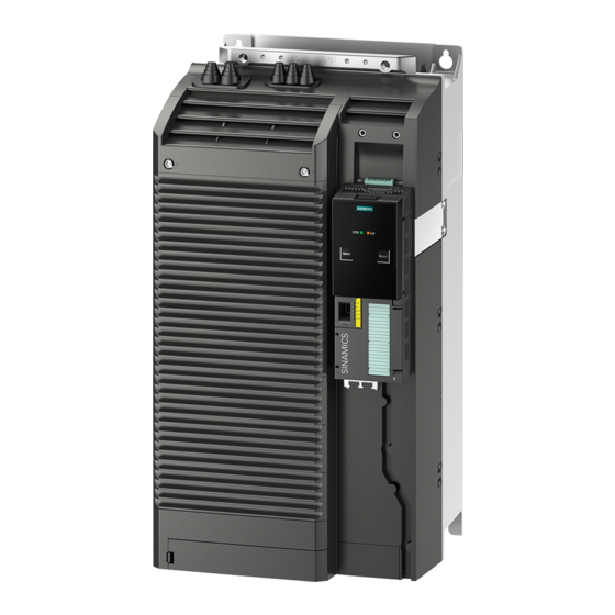
Power modules pm240p-2, ip20
Hide thumbs
Also See for SINAMICS G120:
- List manual (1256 pages) ,
- Manual (732 pages) ,
- Operating instructions manual (550 pages)

Related Manuals for Siemens SINAMICS G120


Summary of Contents for Siemens SINAMICS G120
- Page 1 SINAMICS SINAMICS G120 inverter Power Modules PM240P-2, IP20 Hardware Installation Manual Edition 11/2016...
- Page 3 Changes in this manual Fundamental safety instructions Introduction SINAMICS Installing/mounting SINAMICS G120 PM240P-2 Power Modules Connecting-up Service and maintenance Hardware Installation Manual Technical data Spare parts and accessories Appendix 11/2016 11/2016 A5E37800827C AB...
- Page 4 Note the following: WARNING Siemens products may only be used for the applications described in the catalog and in the relevant technical documentation. If products and components from other manufacturers are used, these must be recommended or approved by Siemens. Proper transport, storage, installation, assembly, commissioning, operation and maintenance are required to ensure that the products operate safely and without any problems.
-
Page 5: Table Of Contents
Table of contents Changes in this manual..........................7 Fundamental safety instructions........................9 General safety instructions.......................9 Handling electrostatic sensitive devices (ESD)..............14 Industrial security........................15 Residual risks of power drive systems...................16 Introduction..............................17 Component specification according to UL................18 Permissible motors.........................19 Installing/mounting............................21 Installation conditions......................21 EMC-compliant installation of a machine the system.............23 4.2.1 Control cabinet........................24 4.2.2... - Page 6 Table of contents Replacing a fan........................55 Technical data............................57 Electromagnetic compatibility - overview ................58 Ambient conditions.........................59 Overload capability of the inverter..................60 Cable cross-sections and tightening torques.................62 Technical data, 400 V inverters....................63 7.5.1 General data, 400 V inverters....................63 7.5.2 Specific technical data, 400 V inverters.................65 7.5.3 Current derating depending on the pulse frequency, 400 V inverters........67 Technical data, 690 V inverters....................68...
-
Page 7: Changes In This Manual
Changes in this manual First edition The Power Modules of the PM240P-2 series are especially suitable for driving pumps and fans. PM240P-2 Power Modules Hardware Installation Manual, 11/2016, A5E37800827C AB... - Page 8 Changes in this manual PM240P-2 Power Modules Hardware Installation Manual, 11/2016, A5E37800827C AB...
-
Page 9: Fundamental Safety Instructions
Fundamental safety instructions General safety instructions DANGER Danger to life due to live parts and other energy sources Death or serious injury can result when live parts are touched. ● Only work on electrical devices when you are qualified for this job. ●... -
Page 10: Technical Data
Fundamental safety instructions 2.1 General safety instructions WARNING Danger to life when live parts are touched on damaged devices Improper handling of devices can cause damage. For damaged devices, hazardous voltages can be present at the enclosure or at exposed components;... - Page 11 Fundamental safety instructions 2.1 General safety instructions NOTICE Material damage due to loose power connections Insufficient tightening torques or vibrations can result in loose electrical connections. This can result in damage due to fire, device defects or malfunctions. ● Tighten all power connections with the specified tightening torques, e.g. line supply connection, motor connection, DC link connections.
- Page 12 Fundamental safety instructions 2.1 General safety instructions WARNING Danger to life due to the motor catching fire in the event of insulation overload There is higher stress on the motor insulation through a ground fault in an IT system. If the insulation fails, it is possible that death or severe injury can occur as a result of smoke and fire.
- Page 13 Fundamental safety instructions 2.1 General safety instructions WARNING Danger to life when safety functions are inactive Safety functions that are inactive or that have not been adjusted accordingly can cause operational faults on machines that could lead to serious injury or death. ●...
-
Page 14: Handling Electrostatic Sensitive Devices (Esd)
Fundamental safety instructions 2.2 Handling electrostatic sensitive devices (ESD) Handling electrostatic sensitive devices (ESD) Electrostatic sensitive devices (ESD) are individual components, integrated circuits, modules or devices that may be damaged by either electric fields or electrostatic discharge. NOTICE Damage through electric fields or electrostatic discharge Electric fields or electrostatic discharge can cause malfunctions through damaged individual components, integrated circuits, modules or devices. -
Page 15: Industrial Security
Siemens’ products and solutions undergo continuous development to make them more secure. Siemens strongly recommends to apply product updates as soon as available and to always use the latest product versions. Use of product versions that are no longer supported, and failure to apply latest updates may increase customer’s exposure to cyber threats. -
Page 16: Residual Risks Of Power Drive Systems
Fundamental safety instructions 2.4 Residual risks of power drive systems Residual risks of power drive systems When assessing the machine- or system-related risk in accordance with the respective local regulations (e.g., EC Machinery Directive), the machine manufacturer or system installer must take into account the following residual risks emanating from the control and drive components of a drive system: 1. -
Page 17: Introduction
Introduction Overview The Power Modules belong to the modular family of SINAMICS G120 inverters. A modular inverter comprises Control Unit and Power Module. Depending on the power rating in frame sizes FSD … FSF, the following Power Module versions are supplied: ●... -
Page 18: Component Specification According To Ul
You can find proof of the certification on the Internet UL certificates (http://www.ul.com) under "Tools / Online Certifications Directory" by entering the file number or the "Name". The UL file number for the Power Modules of the SINAMICS G120 product family is: ● E192450 for FSD, FSE and FSF... -
Page 19: Permissible Motors
Introduction 3.2 Permissible motors Permissible motors Note Motors for inverter operation Only use motors that are suitable for operation with inverters with a DC link. Motors for 400 V Power Modules For the 400 V Power Modules, induction motors are permissible in the range from 25 % …... - Page 20 Introduction 3.2 Permissible motors PM240P-2 Power Modules Hardware Installation Manual, 11/2016, A5E37800827C AB...
-
Page 21: Installing/Mounting
– Fuse types: Technical data (Page 57) – Circuit breaker (https://support.industry.siemens.com/cs/ww/en/view/109486009) ● The integrated semiconductor short-circuit protection does not provide cable protection. ● On the system side, provide cable protection in conformance with NEC or CEC, Part 1 and the local regulations. - Page 22 Installing/mounting 4.1 Installation conditions Additional requirements relating to CSA conformance, frame sizes FSD … FSF Overvoltage category OVC III must be ensured for all connections of the power circuit. This can mean that a surge suppressor must connected upstream on the line side. The rated voltage of the surge suppressor must not exceed the line voltage, and must guarantee the limit values (VPR) specified here.
-
Page 23: Emc-Compliant Installation Of A Machine The System
Installing/mounting 4.2 EMC-compliant installation of a machine the system EMC-compliant installation of a machine the system The inverter is designed for operation in industrial environments where strong electromagnetic fields are to be expected. Reliable and disturbance-free operation is only guaranteed for EMC-compliant installation. To achieve this, subdivide the control cabinet and the machine or system into EMC zones: EMC zones Figure 4-1... -
Page 24: Control Cabinet
Installing/mounting 4.2 EMC-compliant installation of a machine the system 4.2.1 Control cabinet ● Assign the various devices to zones in the control cabinet. ● Electromagnetically uncouple the zones from each other by means of one of the following actions: – Side clearance ≥ 25 cm –... -
Page 25: Cables
Further information Additional information about EMC-compliant installation is available in the Internet: EMC installation guideline (https://support.industry.siemens.com/cs/ww/de/view/60612658/ 4.2.2 Cables Cables with a high level of interference and cables with a low level of interference are connected to the inverter: ●... - Page 26 Installing/mounting 4.2 EMC-compliant installation of a machine the system Cable routing inside the cabinet ● Route the power cables with a high level of interference so that there is a minimum clearance of 25 cm to cables with a low level of interference. If the minimum clearance of 25 cm is not possible, insert separating metal sheets between the cables with a high level of interference and cables with a low level of interference.
- Page 27 Installing/mounting 4.2 EMC-compliant installation of a machine the system Routing cables outside the control cabinet ● Maintain a minimum clearance of 25 cm between cables with a high level of interference and cables with a low level of interference. ● Using shielded cables for the following connections: –...
-
Page 28: Electromechanical Components
Installing/mounting 4.2 EMC-compliant installation of a machine the system 4.2.3 Electromechanical components Radio interference suppression ● Connect interference suppression elements to the following components: – Coils of contactors – Relays – Solenoid valves – Motor holding brakes ● Connect the interference suppression element directly at the coil. ●... -
Page 29: Power Losses And Air Cooling Requirements
Installing/mounting 4.3 Power losses and air cooling requirements Power losses and air cooling requirements Cooling requirements To protect the components from overheating, the control cabinet requires a cooling air flow, which depends on the power loss of the individual components. Formula for calculating the cooling airflow: airflow [l/s] = power loss [W] * 0.86 / ΔT [K] ●... -
Page 30: Mounting The Power Modules
Installing/mounting 4.4 Mounting the Power Modules Mounting the Power Modules Protection against the spread of fire The device may be operated only in closed housings or in control cabinets with protective covers that are closed, and when all of the protective devices are used. The installation of the device in a metal control cabinet or the protection with another equivalent measure must prevent the spread of fire and emissions outside the control cabinet. -
Page 31: Dimension Drawings And Drilling Dimensions
Installing/mounting 4.4 Mounting the Power Modules 4.4.1 Dimension drawings and drilling dimensions The following dimensioned drawings and drilling patterns are not to scale. Table 4-1 Mounting dimensions Frame size Width (mm) Height (mm) Depth (mm) Power Module Shield plate at the bottom The Power Modules can be mounted and operated side-by-side. -
Page 32: Hoisting Gear
Installing/mounting 4.4 Mounting the Power Modules Drilling dimensions and cooling air clearances Table 4-2 Drilling dimensions, cooling air clearances [mm] and fixing [Nm] Frame Drilling dimensions Cooling air clearances Fixing size Bottom Front Screws/torque 4 x M5 / 6 4 x M6 / 10 4 x M8 / 25 You can mount the Power Modules without any lateral cooling air clearance. -
Page 33: Mounting The Shield Plate And Emc Connecting Bracket
Installing/mounting 4.4 Mounting the Power Modules 4.4.3 Mounting the shield plate and EMC connecting bracket Mounting the shield plate and EMC connecting bracket, FSD … FSF Use the shield plate provided for strain relief of the line and motor cable – as well as the shield support for the motor cable. - Page 34 Installing/mounting 4.4 Mounting the Power Modules Procedure - FSF: Proceed as follows to mount the EMC connecting bracket and the shield plate: ① 1. Attach the EMC connecting bracket to the shield plate ② 2. Screw the shield module to the inverter using three screws, as shown in the diagram.
-
Page 35: Additional Components
Installing/mounting 4.5 Additional components Additional components Depending on the particular application, additional components may be required for your system. Information about additional components is provided in the following Sections: Connection overview (Page 45) Optional accessories (Page 85). PM240P-2 Power Modules Hardware Installation Manual, 11/2016, A5E37800827C AB... - Page 36 Installing/mounting 4.5 Additional components PM240P-2 Power Modules Hardware Installation Manual, 11/2016, A5E37800827C AB...
-
Page 37: Connecting-Up
To protect against indirectly touching part of the motor circuit of an inverter and to automatically shut down in the case of a fault according to DIN EN 60364-4-41 (VDE 0100-410). (http:// support.automation.siemens.com/WW/view/en/103474630) WARNING Danger to life due to electric shock if there is poor touch protection Death or injury can occur if accessible parts or connections, which are live, are touched. - Page 38 Connecting-up WARNING Danger to life due to fire or electric shock when using unsuitable residual current protection devices The inverter can cause a current to flow in the protective conductor. This current can cause the residual current device (RCD) or residual current monitoring (RCM) to incorrectly trip (nuisance trip).
- Page 39 Connecting-up ● For inverters with rated input currents> 125 A referred to LO, use a type B MRCD (for example, from the Bender company). An MRCD comprises an RCM (differential current monitoring device), a measuring current transducer and a circuit breaker with additional undervoltage release, listed in the Technical data.
-
Page 40: Permissible Line Supplies
Connecting-up 5.1 Permissible line supplies Permissible line supplies Restrictions for installation altitudes above 2000 m Above an installation altitude of 2000 m, the permissible line supplies are restricted. Restrictions for special ambient conditions (Page 74) General requirements on line supply The plant builder or machine manufacturer must ensure for operation with rated current I rated that the voltage drop between the transformer input terminals and the inverter when operated... -
Page 41: Tt Line System
Connecting-up 5.1 Permissible line supplies 5.1.2 TT line system In a TT line system, the transformer grounding and the installation grounding are independ‐ ent of one another. There are TT line supplies where the neutral conductor N is either transferred – or not. Inverter operated on a TT line system ●... - Page 42 Connecting-up 5.1 Permissible line supplies Behavior of the inverter when a ground fault occurs In some instances, even for a ground fault, the inverter should still remain functional. In cases such as these, you must install an output reactor. This prevents an overcurrent trip or damage to the drive.
-
Page 43: Protective Conductor
Connecting-up 5.1 Permissible line supplies 5.1.4 Protective conductor WARNING Danger to life caused by high leakage currents for an interrupted protective conductor The drive components conduct a high leakage current via the protective conductor. Touching conductive parts when the protective conductor is interrupted can result in death or serious injury. - Page 44 Connecting-up 5.1 Permissible line supplies ① Additional requirements placed on the protective conductor ● For permanent connection, the protective conductor must fulfill at least one of the following conditions: – The protective conductor is routed so that it is protected against damage along its complete length.
-
Page 45: Connecting The Line And Motor Cable At The Inverter
Connecting-up 5.2 Connecting the line and motor cable at the inverter Connecting the line and motor cable at the inverter 5.2.1 Connection overview Figure 5-2 Block diagram PM240P-2 Figure 5-3 Connection overview PM240P-2 Power Modules Hardware Installation Manual, 11/2016, A5E37800827C AB... - Page 46 Connecting-up 5.2 Connecting the line and motor cable at the inverter Connect cables at the inverter so that they are EMC compliant Attach the cable tie holders to the Power Module as shown to the left in the diagram before you establish the connections.
-
Page 47: Length Of Motor Cable
Connecting-up 5.2 Connecting the line and motor cable at the inverter 5.2.2 Length of motor cable Always dimension the motor cable so that the ohmic losses are less than 5 % of the inverter power rating. The permissible length of the motor cable also depends on the quality of the motor cable and the inverter pulse frequency. -
Page 48: Establishing Connections
Connecting-up 5.2 Connecting the line and motor cable at the inverter 5.2.3.1 Establishing connections Procedure Proceed as follows to establish the connections: 1. Ensure that the device is in a no-voltage condition and the DC link is discharged. 2. Establish the connections as described in the following sections. This means that you have established the connections. - Page 49 Connecting-up 5.2 Connecting the line and motor cable at the inverter Figure 5-5 Line and motor connections You must re-attach the connection covers in order to re-establish the touch protection of the inverter after it has been connected up. PM240P-2 Power Modules Hardware Installation Manual, 11/2016, A5E37800827C AB...
-
Page 50: Sto Via Power Module Terminals
Connecting-up 5.3 STO via Power Module terminals STO via Power Module terminals With Power Modules, frame sizes FSD … FSF, you can implement the "Safe Torque Off" (STO) safety function, corresponding to PL e according to EN 13849-1 and SIL 3 to IEC61508. -
Page 51: Connecting The Motor To The Inverter In A Star Or Delta Connection
Connecting-up 5.4 Connecting the motor to the inverter in a star or delta connection Connecting the motor to the inverter in a star or delta connection Standard induction motors with a rated power of approximately ≤ 3 kW are normally connected in a star/delta connection (Y/Δ) at 400 V/230 V. - Page 52 Connecting-up 5.4 Connecting the motor to the inverter in a star or delta connection PM240P-2 Power Modules Hardware Installation Manual, 11/2016, A5E37800827C AB...
-
Page 53: Service And Maintenance
WARNING Danger due to incorrect repair Repairs may only be carried out by Siemens Service, by repair centers authorized by Siemens or by authorized personnel who are thoroughly acquainted with all the warnings and operating procedures contained in this manual. -
Page 54: Maintenance
Note The actual maintenance intervals depend on the installation and operating conditions. Siemens offers its customers support in the form of service contracts. For further information, contact your Siemens regional office or sales office. PM240P-2 Power Modules Hardware Installation Manual, 11/2016, A5E37800827C AB... -
Page 55: Replacing A Fan
Service and maintenance 6.2 Replacing a fan Replacing a fan Service life of the fan The average service life of the fan is 40,000 hours. In practice, however, the service life may deviate from this value. Especially a dusty environment can block up the fan. The fan must be replaced in good time to ensure that the inverter is ready for operation. - Page 56 Service and maintenance 6.2 Replacing a fan When inserting the fan unit, you establish the electrical connection between the inverter and fan unit. PM240P-2 Power Modules Hardware Installation Manual, 11/2016, A5E37800827C AB...
-
Page 57: Technical Data
Technical data Note Power loss of the Power Modules The values specified for the power loss are typical values at 90% of the rated speed and 100% of the load corresponding to Low Overload. Note Motors for inverter operation Only use motors that are suitable for operation with inverters with a DC link. PM240P-2 Power Modules Hardware Installation Manual, 11/2016, A5E37800827C AB... -
Page 58: Electromagnetic Compatibility - Overview
Technical data 7.1 Electromagnetic compatibility - overview Electromagnetic compatibility - overview Electromagnetic compatibility according to EN61800-3 Property Version Interference immunity The inverters are suitable for use in the first and second industrial environments Interference emission - Category C2 for inverters with integrated radio interference suppression filter second environment Category C2 for inverters without filter with optional external radio interference suppression... -
Page 59: Ambient Conditions
Technical data 7.2 Ambient conditions Ambient conditions Property Version Ambient conditions for transport in the transport packaging Climatic ambient conditions ‑ 40 °C … + 70 °C, according to Class 2K4 to EN 60721‑3‑2 maximum humidity 95 % at 40 °C Mechanical ambient condi‐... -
Page 60: Overload Capability Of The Inverter
Low Overload. We recommend the "SIZER" engineering software to select the inverter. You will find additional information about SIZER on the Internet: Download SIZER (http:// support.automation.siemens.com/WW/view/en/10804987/130000). Load cycles and typical applications: "Low Overload" load cycle "High Overload" load cycle The "Low Overload"... - Page 61 Technical data 7.3 Overload capability of the inverter Typical inverter load cycles Figure 7-1 "Low Overload" and "High Overload" load cycles PM240P-2 Power Modules Hardware Installation Manual, 11/2016, A5E37800827C AB...
-
Page 62: Cable Cross-Sections And Tightening Torques
Technical data 7.4 Cable cross-sections and tightening torques Cable cross-sections and tightening torques Table 7-1 Connection, cross-section and tightening torque for PM240P-2 Power Modules Inverters Connection Cross-section, tightening torque Stripped insulation Metric Imperial length Line supply, Screw-type termi‐ 10 … 35 mm , 2.5 …... -
Page 63: Technical Data, 400 V Inverters
Short-circuit current rating ≤ 100 kA rms (SCCR) and branch protec‐ Branch protection and short-circuit strength according to UL and IEC (https:// tion support.industry.siemens.com/cs/ww/en/view/109479152) Braking methods DC braking, compound braking Degree of protection ac‐ IP20 Must be installed in a control cabinet... - Page 64 Technical data 7.5 Technical data, 400 V inverters Property Version Touch protection acc. to EN BGV A3 when used for the intended purpose 50274 Cooling in compliance with Forced air cooling AF EN 60146 Current and power limiting depending on the line voltage PM240P-2 Power Modules Hardware Installation Manual, 11/2016, A5E37800827C AB...
-
Page 65: Specific Technical Data, 400 V Inverters
47 A 62 A HO base load output current 38 A 45 A 60 A Siemens fuse according to IEC/UL 3NE1820-0 / 80 A 3NE1021-0 / 100 A 3NE1021-0 / 100 A Fuse according to IEC/UL, Class J 70 A... - Page 66 154 A 189 A HO base load output current 110 A 145 A 178 A Siemens fuse according to IEC/UL 3NE1225-0 / 200 A 3NE1227-0 / 250 A 3NE1230-0 / 315 A Fuse according to IEC/UL, Class J 200 A...
-
Page 67: Current Derating Depending On The Pulse Frequency, 400 V Inverters
Technical data 7.5 Technical data, 400 V inverters 7.5.3 Current derating depending on the pulse frequency, 400 V inverters Article number LO base load output current [A] power [kW] Pulse frequency [kHz] 6SL3210-1RE24-5 . L0 38.3 31.5 22.5 20.3 6SL3210-1RE26-0 . L0 6SL3210-1RE27-5 . -
Page 68: Technical Data, 690 V Inverters
≤ 100 kA rms (SCCR) and branch protec‐ Branch protection and short-circuit strength according to UL and IEC (https:// tion support.industry.siemens.com/cs/ww/en/view/109479152) Braking methods DC braking, compound braking Degree of protection ac‐ IP20; must be installed in a control cabinet cording to EN 60529... - Page 69 Technical data 7.6 Technical data, 690 V inverters Dependent on the input voltage and output power PM240P-2 Power Modules Hardware Installation Manual, 11/2016, A5E37800827C AB...
-
Page 70: Specific Technical Data, 690 V Inverters
14 A 20 A HO base load output current 11 A 14 A 19 A Siemens fuse according to IEC/UL 3NE1815-0 / 25 A 3NE1815-0 / 25 A 3NE1803-0 / 35 A Fuse according to IEC/UL, Class J 20 A... - Page 71 HO base load input current 44 A 54 A HO base load output current 42 A 52 A Siemens fuse according to IEC/UL 3NA1820-0 / 80 A 3NE1820-0 / 80 A Fuse according to IEC/UL, Class J 80 A 80 A Power loss without filter 1.00 kW...
- Page 72 HO base load power 110 kW HO base load input current 122 A HO base load output current 115 A Siemens fuse according to IEC/UL 3NE1225-0 / 200 A Fuse according to IEC/UL, Class J 200 A Power loss without filter 2.56 kW Power loss with filter 2.59 kW...
-
Page 73: Current Derating Depending On The Pulse Frequency, 690 V Inverters
Technical data 7.6 Technical data, 690 V inverters 7.6.3 Current derating depending on the pulse frequency, 690 V inverters Article number LO pow‐ LO base load output current [A] er [kW] Pulse frequency [kHz] 6SL3210-1RH21-4 . L0 6SL3210-1RH22-0 . L0 11.4 6SL3210-1RH22-3 . -
Page 74: Restrictions For Special Ambient Conditions
Technical data 7.7 Restrictions for special ambient conditions Restrictions for special ambient conditions Maximum current at low speeds NOTICE Negative impact on the inverter service life as a result of overheating. Loading the inverter with a high output current and at the same time with a low output frequency can cause the current-conducting components in the inverter to overheat. - Page 75 Technical data 7.7 Restrictions for special ambient conditions Current reduction as a function of the installation altitude and ambient temperature At installation altitudes above 1000 m and temperatures higher than 40 °C (low overload) or 50 °C (high overload), the inverter output current is reduced. Details are provided in the tables below.
- Page 76 Technical data 7.7 Restrictions for special ambient conditions Note Using Power Modules connected to TN line supplies with voltages ≥ 600 V for installation altitudes 2000 m … 4000 m For voltages ≥ 600 V, the TN line supply must have a grounded neutral point established using an isolating transformer.
-
Page 77: Electromagnetic Compatibility Of Variable-Speed Drives
Technical data 7.8 Electromagnetic compatibility of variable-speed drives Electromagnetic compatibility of variable-speed drives EMC (electromagnetic compatibility) means that the devices function satisfactorily without interfering with other devices and without being disrupted by other devices. This is true when the emitted interference (emission level) and the interference immunity are matched with each other. -
Page 78: Inverter Applications
- and are not operated in the general public domain. For an EMC-compliant installation, observe the information provided in the Configuration manual: EMC installation guideline (http://support.automation.siemens.com/WW/view/en/ 60612658). The Power Modules described here are intended for operation in the first and second environments. -
Page 79: Operation In The First Environment
Interference emission - operation in the second environment, Category C4 When connected to IT line supplies, only filtered inverters are permissible. Use external filters without capacitors with respect to ground to limit symmetrical interference emission. When necessary, contact one of our Solution Partners (https://www.automation.siemens.com/ solutionpartner/partnerfinder/Home/Index? country=DE&program=1&technology=19&lang=en). 7.8.1.2... -
Page 80: Harmonic Currents
Technical data 7.8 Electromagnetic compatibility of variable-speed drives ● Inverters with an LO base load input current > 16 A and ≤ 75 A The drive system is in compliance with IEC/EN 61000-3-12 under the following precondition: – Power Module FSD, input voltage 380 … 480 V 3 AC: A line reactor is not required –... -
Page 81: Emc Limit Values In South Korea
In addition, measures for EMC-compliant configuration of the plant or system are described in detail in this manual and in the Configuration manualEMC installation guideline (http:// support.automation.siemens.com/WW/view/en/60612658). The final statement on compliance with the applicable standard is given by the respective label attached to the individual device. - Page 82 Technical data 7.8 Electromagnetic compatibility of variable-speed drives PM240P-2 Power Modules Hardware Installation Manual, 11/2016, A5E37800827C AB...
-
Page 83: Spare Parts And Accessories
Spare parts and accessories Product maintenance Continuous development within the scope of product maintenance Inverter components are being continuously developed within the scope of product maintenance. Product maintenance includes, for example, measures to increase the ruggedness or hardware changes which become necessary as components are discontinued. These further developments are "spare parts-compatible"... -
Page 84: Spare Parts
*) Included in the scope of delivery of the inverter Spare parts through Spares on Web Spares on Web (https://www.automation.siemens.com/sow) When you enter the article number and serial number of your device, you obtain a spare parts list current at the time of your inquiry. -
Page 85: Optional Accessories
Spare parts and accessories 8.3 Optional accessories Optional accessories Which components are available? ● Shield plate at the top ● Motor holding brake controlled using a Brake Relay or Safe Brake Relay Connection components Connection overview for the electrical components Connection overview (Page 45). - Page 86 Spare parts and accessories 8.3 Optional accessories Note Brake Relay and Safe Brake Relay The Brake Relay and the Safe Brake Relay do not differ from each other in the installation and the connection to the inverter. Connection to the inverter To ensure that you have the correct cable for connecting the Brake Relay irrespective of the inverter size, you are supplied with two preassembled cables with different lengths.
-
Page 87: Technical Data Of The Brake Relay
Spare parts and accessories 8.3 Optional accessories Safe Brake Relay - connection and circuit diagram 8.3.2.1 Technical data of the brake relay? Brake Relay Safe Brake Relay 6SL3252-0BB00-0AA0 6SL3252-0BB01-0AA0 Input voltage via the Power Module 20.4 ... 28.8 VDC Input current via the Power Module Max. -
Page 88: Mounting And Connecting The Brake Relay
Spare parts and accessories 8.3 Optional accessories 8.3.2.2 Mounting and connecting the Brake Relay Mounting the Brake Relay Mount the Brake Relay at the rear of the shield plate. Mount it before you mount the shield plate. Mounting the shield plate and EMC connecting bracket (Page 33) Connecting the Brake Relay to the inverter The connector for the Brake Relay is located at the front of the Power Module. -
Page 89: Appendix
Installing, commissioning and maintaining the inverter. Advanced commissioning ● CU250S-2 Compact Operating Instructions (https://support.industry.siemens.com/cs/ww/ en/view/99730303) Installing, commissioning and maintaining the inverter. Advanced commissioning ● CU230P-2 List Manual (https://support.industry.siemens.com/cs/ww/en/view/109477248) Parameter list, alarms and faults. Graphic function diagrams PM240P-2 Power Modules Hardware Installation Manual, 11/2016, A5E37800827C AB... -
Page 90: Configuring Support
Catalog Ordering data and technical information for SINAMICS G inverters. Catalog D31 for download or online catalog (Industry Mall): All about SINAMICS G120 (www.siemens.com/sinamics-g120) SIZER The configuration tool for SINAMICS, MICROMASTER and DYNAVERT T drives, motor starters, as well as SINUMERIK, SIMOTION controllers and SIMATIC technology... -
Page 91: Product Support
A.1 Manuals and technical support EMC Guidelines configuration manual EMC-compliant control cabinet design, potential equalization and cable routing EMC installation guideline (http://support.automation.siemens.com/WW/view/en/60612658) Safety Integrated for novices technical overview Application examples for SINAMICS G drives with Safety Integrated Safety Integrated for novices (https://support.industry.siemens.com/cs/ww/en/view/... -
Page 92: Disposal
Disposal Protecting the environment and preserving its resources are corporate goals of the highest priority for Siemens. Our worldwide environmental management system according to ISO 14001 ensures compliance with legislation and sets high standards in this regard. Environmentally friendly design, technical safety and health protection are always firm goals, even at the product development stage. -
Page 93: Directives And Standards
Appendix A.3 Directives and standards Directives and standards Relevant directives and standards The following directives and standards are relevant for the inverters: European Low Voltage Directive The inverters fulfil the requirements stipulated in the Low-Voltage Directive 2014/35/EU, if they are covered by the application area of this directive. European Machinery Directive The inverters fulfil the requirements stipulated in the Machinery Directive 2006/42//EU, if they are covered by the application area of this directive. - Page 94 Appendix A.3 Directives and standards Quality systems Siemens AG employs a quality management system that meets the requirements of ISO 9001 and ISO 14001. Certificates for download ● EC Declaration of Conformity: (https://support.industry.siemens.com/cs/ww/en/view/ 58275445) ● Certificates for the relevant directives, prototype test certificates, manufacturers declarations and test certificates for functions relating to functional safety ("Safety...
-
Page 95: Abbreviations
Appendix A.4 Abbreviations Abbreviations Abbreviation State Alternating current Communauté Européenne Control Unit Direct current Digital input DIP switch Digital output Equivalent circuit diagram European Economic Community ELCB Earth leakage circuit breaker Electromagnetic compatibility (EMC) Electromagnetic interference FS… Frame size ... Getting Started Guide High overload Input/Output... - Page 96 Appendix A.4 Abbreviations PM240P-2 Power Modules Hardware Installation Manual, 11/2016, A5E37800827C AB...
-
Page 97: Index
Index 87 Hz characteristic, 51 Hardware Installation Manual, 89 Harmonic currents, 80 High Overload, 60 Hotline, 91 Air barrier, 29 Industry Mall, 90 Installation altitude, 75 Base load, 60 Installing, 30 Base load input current, 60 Base load output current, 60 Base load power, 60 Brake Relay, 85 List Manual, 89... - Page 98 Index Support, 91 PM240P-2 Power Modules Hardware Installation Manual, 11/2016, A5E37800827C AB...
-
Page 100: Further Information
Further information SINAMICS inverters: www.siemens.com/sinamics Siemens AG Subject to change Digital Factory © Siemens AG 2016 Motion Control Frauenauracher Str. 80 Scan the QR code for DE-91056 Erlangen additional informati- on about the SINAMICS G120. www.siemens.com/drives...