Sony TDM-iP1 Service Manual
Digital media port adapter
Hide thumbs
Also See for TDM-iP1:
- Operating instructions manual (200 pages) ,
- Operating instructions manual (56 pages) ,
- Specifications (2 pages)
Table of Contents
Advertisement
Quick Links
SERVICE MANUAL
Ver. 1.0 2007.04
Sony Corporation
9-887-706-01
Home Audio Division
2007D02-1
Published by Sony Techno Create Corporation
© 2007.04
SPECIFICATIONS
Output
Video
1 Vp-p 75 ohm
(Composite Video out)
General
Power requirements
DC IN: 5 V, 700 mA
(via DIGITAL MEDIA PORT)
Dimensions (w/d/h)
Approx. 90 × 78 × 65 mm
× 3
× 12
(3
5
/
1
/
5
/
inch)
8
8
8
Mass
Approx. 225 g (7.26 oz)
(includes cable)
Cable length
2 m (6 ft)
Design and specifications are subject to change
without notice.
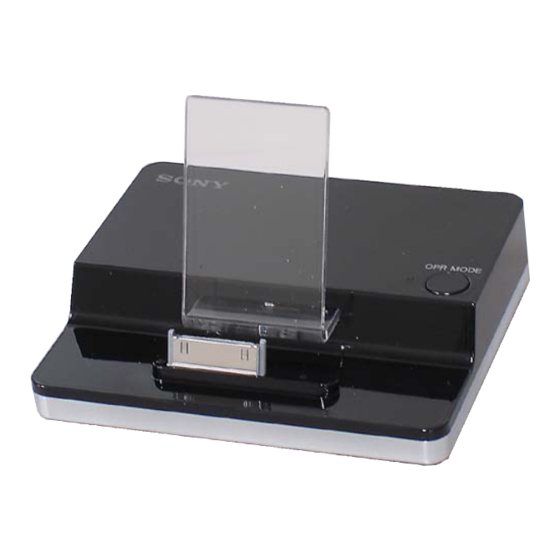
DIGITAL MEDIA PORT ADAPTER
TDM-iP1
Canadian Model
AEP Model
US Model
Advertisement
Table of Contents

Related Manuals for Sony TDM-iP1


Summary of Contents for Sony TDM-iP1
- Page 1 Approx. 225 g (7.26 oz) (includes cable) Cable length 2 m (6 ft) Design and specifications are subject to change without notice. DIGITAL MEDIA PORT ADAPTER Sony Corporation 9-887-706-01 Home Audio Division 2007D02-1 Published by Sony Techno Create Corporation © 2007.04...
-
Page 2: Unleaded Solder
TDM-iP1 On copyrights UNLEADED SOLDER • iPod is a trademark of Apple Inc., registered in the U.S. and other Boards requiring use of unleaded solder are printed with the lead- countries. free mark (LF) indicating the solder contains no lead. -
Page 3: Section 1 General
TDM-iP1 SECTION 1 GENERAL LIST OF PARTS LOCATIONS This section is extracted from instruction manual. O U T VI D EO 1 DIGITAL MEDIA PORT cable 2 LED status indicator iPod Display mode : Lights up in amber. On Screen Display mode : Lights up in green. -
Page 4: Section 3 Diagrams
TDM-iP1 SECTION 3 DIAGRAMS • Note for Printed Wiring Boards and Schematic Diagrams Note on Printed Wiring Boards. Note on Schematic Diagrams. • All capacitors are in µF unless otherwise noted. (p: pF) • X : parts extracted from the component side •... -
Page 5: Block Diagram
TDM-iP1 3-1. BLOCK DIAGRAM CN001 IC009 + 3.3V CN002 + 3.3V REG V-VIDEO + 5V V-VIDEO VBUS V-BUS LINE-OUT-L LINE-OUT-R DMPORT IC015 VIDEO-OUT VIDEO iPOD IC010 VIDEO_SEL_1 Q002-005 VIDEO MUTING VIDEO_SEL_2 SWITCH X001 X002 IC006 17.734475MHz 14.31858MHz LEVEL SHIFT DGND... -
Page 6: Printed Wiring Board - Main Board
TDM-iP1 :Uses unleaded solder. 3-2. PRINTED WIRING BOARD – MAIN BOARD – TO DMPORT S012 MAIN BOARD (SIDE A) MAIN BOARD (SIDE B) OPR MODE C074 C075 D011 S001 R093 S013 OPR MODE NTSC TEST CN001 C050 C070 R095 R100... - Page 7 TDM-iP1 3-3. BLOCK DIAGRAM – MAIN SECTION – • See page 4 for Waveforms. • See page 8 for IC Block Diagrams. • See page 9, 10 for IC Pin Function Description. MAIN BOARD CN007 R078 CN002 TXD1 R079 CL188...
- Page 8 TDM-iP1 • IC Block Diagrams IC006 (TC7WHU04FK (T5RSOYF) ) IC007 (TC74VHC00FK) IC009 (TH11133CSGL-G) 1A 1 Vcont 1 500kΩ 320kΩ 1A 1 1B 2 CONTROL 3Y 2 1Y 3 CIRCUIT BANDGAP REFERENCE GND 2 2A 3 2A 4 OVER HEAT &...
- Page 9 TDM-iP1 • IC Pin Function Description IC003 M30624MGP-B50GPU0 (SYSTEM CONTROL) Pin No. Pin Name Desciption IPOD_DET iPod detection terminal NO_USE Not used (Open) OSD_DATA Data output to OSD controller (IC001) (OSD: On Screen Display) OSD_BUSY Busy input from OSD controller (IC001)
- Page 10 TDM-iP1 Pin No. Pin Name Desciption EEPROM_CLK EEPROM clock output EEPROM_CE EEPROM chip enable output 80-88 NO_USE Not used (Open) KEY1 Key Input1 KEY0 Key Input0 91-93 NO_USE Not used (Open) AVss Ground terminal NO_USE Not used (Open) Vref Reference voltage terminal Power supply terminal (+3.3V)
- Page 11 TDM-iP1 IC001 MB90050PF-G-121-MSE (ON SCREEN DISPLAY CONROLLER) Pin No. Pin Name Description FLD1 Field signal input VSYNCI Vertical sync signal input HSYNCI Holizontal sync signal input Power supply terminal for digital section (+5V) Ground terminal Clock input for color burst...
-
Page 12: Section 4 Exploded Views
TDM-iP1 SECTION 4 EXPLODED VIEWS NOTE: • The mechanical parts with no reference • -XX and -X mean standardized parts, so they number in the exploded views are not supplied. may have some difference from the original • Accessories are given in the last of the one. -
Page 13: Section 5 Electrical Parts List
TDM-iP1 SECTION 5 MAIN ELECTRICAL PARTS LIST NOTE: • Due to standardization, replacements in the • SEMICONDUCTORS In each case, u: µ, for example: parts list may be different from the parts When indicating parts by reference uA... : µA... - Page 14 TDM-iP1 MAIN Ref. No. Part No. Description Remark Ref. No. Part No. Description Remark < TRANSISTOR > R083 1-218-941-81 RES-CHIP 1/16W R084 1-218-965-11 RES-CHIP 1/16W Q001 8-729-620-13 TRANSISTOR 2SC4154TP-1EF R088 1-216-809-11 METAL CHIP 1/10W Q002 6-551-399-01 TRANSISTOR 2SC5996-T111-1B R090 1-218-941-81 RES-CHIP...
- Page 15 TDM-iP1 MAIN Ref. No. Part No. Description Remark Ref. No. Part No. Description Remark < SWITCH > S001 1-771-246-21 SWITCH, SLIDE (NTSC/PAL) (AEP) S012 1-786-700-11 SWITCH, TACTILE (OPR MODE) S013 1-786-700-11 SWITCH, TACTILE (TEST) < VIBRATOR > X001 1-813-921-11 VIBRATOR, CRYSTAL (17.734475 MHz) (AEP) X002 1-813-930-11 VIBRATOR, CRYSTAL (14.31818 MHz)
-
Page 16: Revision History
TDM-iP1 REVISION HISTORY Clicking the version allows you to jump to the revised page. Also, clicking the version at the upper right on the revised page allows you to jump to the next revised page. Ver. Date Description of Revision...