Advertisement
S
ervice
M anua l
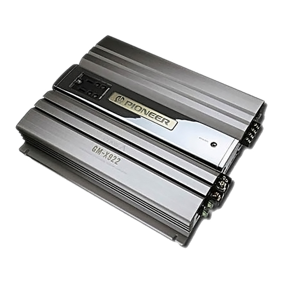
BRIDGEABLE POWER AMPLIFIER
GM-X922
GM-X1022
CONTENTS
1. SAFETY INFORMATION ............................................2
2. EXPLODED VIEWS AND PARTS LIST .......................3
3. SCHEMATIC DIAGRAM .............................................8
4. PCB CONNECTION DIAGRAM ................................10
5. ELECTRICAL PARTS LIST ........................................13
PIONEER ELECTRONIC CORPORATION
PIONEER ELECTRONICS SERVICE INC.
PIONEER ELECTRONIC [EUROPE] N.V.
PIONEER ELECTRONICS ASIACENTRE, PTE.LTD. 501 Orchard Road, #10-00, Wheelock Place, Singapore 238880
C PIONEER ELECTRONIC CORPORATION 1998
4-1, Meguro 1-Chome, Meguro-ku, Tokyo 153-8654, Japan
P.O.Box 1760, Long Beach, CA 90801-1760 U.S.A.
Haven 1087 Keetberglaan 1, 9120 Melsele, Belgium
X1R/UC, ES, EW
X1R/UC
6. ADJUSTMENT..........................................................17
7. GENERAL INFORMATION .......................................18
7.1 IC .........................................................................18
7.2 DISASSEMBLY ...................................................19
8. OPERATIONS AND SPECIFICATIONS.....................20
K-ZEU. FEB. 1998 Printed in Japan
ORDER NO.
CRT2157
Advertisement
Table of Contents

Related Manuals for Pioneer GM-X922/X1R/UC


Summary of Contents for Pioneer GM-X922/X1R/UC
-
Page 1: Table Of Contents
P.O.Box 1760, Long Beach, CA 90801-1760 U.S.A. PIONEER ELECTRONIC [EUROPE] N.V. Haven 1087 Keetberglaan 1, 9120 Melsele, Belgium PIONEER ELECTRONICS ASIACENTRE, PTE.LTD. 501 Orchard Road, #10-00, Wheelock Place, Singapore 238880 C PIONEER ELECTRONIC CORPORATION 1998 K-ZEU. FEB. 1998 Printed in Japan... -
Page 2: Safety Information
GM-X922, GM-X1022 1. SAFETY INFORMATION This service manual is intended for qualified service technicians; it is not meant for the casual do-it-yourselfer. Qualified technicians have the necessary test equipment and tools, and have been trained to properly and safely repair complex products such as those covered by this manual. -
Page 3: Exploded Views And Parts List
GM-X922, GM-X1022 2. EXPLODED VIEWS AND PARTS LIST 2.1 PACKING Fig. 1... - Page 4 See Contrast table (2) 10-3 Card See Contrast table (2) 10-4 Warranty Card See Contrast table (2) (2) CONTRAST TABLE GM-X922/X1R/UC, GM-X922/X1R/ES, GM-X922/X1R/EW and GM-X1022/X1R/UC are constructed the same except for the following: Part No. GM-X922 GM-X1022 Mark No. Symbol and Description...
- Page 5 GM-X922, GM-X1022 2.2 EXTERIOR Fig. 2...
- Page 6 GM-X922, GM-X1022 (1) EXTERIOR SECTION PARTS LIST Mark No. Description Part No. Mark No. Description Part No. 1 Screw BMZ30P250FZK 46 Separator HNM0046 2 Screw CBA1323 47 Terminal(CN101) HKE0010 3 Screw CBA1382 48 Fuse Holder(CN902) HKE0012 4 Screw HBA0006 49 Terminal(CN901) HKE0014 5 Screw HBA0011...
- Page 7 GM-X922, GM-X1022 (2) CONTRAST TABLE GM-X922/X1R/UC, GM-X922/X1R/ES, GM-X922/X1R/EW and GM-X1022/X1R/UC are constructed the same except for the following: Part No. GM-X922 GM-X1022 Mark No. Symbol and Description X1R/UC X1R/ES X1R/EW X1R/UC Amp Unit HWH0072 HWH0070 HWH0069 HWH0071 Network Unit HWG0014...
-
Page 8: Schematic Diagram
FIL UNIT B.B UNIT GAIN BUFFER AMP ISOLATOR ADJUSTMENT BASS BOOST Except UC model GM-X922/X1R/UC only PRE OUT L PRE OUT R GM-X922/X1R/UC only Except UC model Except GM-X922/X1R/UC ±15V PWM CONTROL REGULATOR ERA92-02VH DC-DC CONVERTER ERA92-02VH A B C... - Page 9 GM-X922, GM-X1022 REGULATOR POWER STAGE OVER VOLTAGE PROTECTOR Except UC model NTROL POWER CONTROL / MUTE HZS7L(B2) B. REMOTE B. REMOTE SENSE SWITCHES : NETWORK UNIT FIL UNIT FAN MOTOR S501 : LPF SWITCH......ON – OFF Consists of CXM1133 FIL UNIT B.B UNIT S551 : BASS / BOOST SWITCH..ON –...
-
Page 10: Pcb Connection Diagram
GM-X922, GM-X1022 4. PCB CONNECTION DIAGRAM 4.1 AMP UNIT NOTE FOR PCB DIAGRAMS AMP UNIT 1. The parts mounted on this PCB include all necessary parts for several destination. For further information for CN552 respective destinations, be sure to check with the schematic dia- gram. - Page 11 GM-X922, GM-X1022 SIDE A FAN MOTOR FAN MOTOR Fig. 4...
- Page 12 GM-X922, GM-X1022 4.2 FIL UNIT, B.B UNIT SIDE A FIL UNIT CN852 B.B UNIT CN201 Fig. 5...
-
Page 13: Electrical Parts List
CKS.., CCS.., CSZS..=====Circuit Symbol and No.===Part Name Part No. =====Circuit Symbol and No.===Part Name Part No. ------ --------------------------------------------- ------------------------- ------ --------------------------------------------- ------------------------- GM-X922/X1R/UC Transistor 2SA1048 Transistor 2SC2458 Unit Number : HWH0072 Transistor 2SA1048 Unit Name : Amp Unit Transistor... - Page 14 GM-X922, GM-X1022 =====Circuit Symbol and No.===Part Name Part No. =====Circuit Symbol and No.===Part Name Part No. ------ --------------------------------------------- ------------------------- ------ --------------------------------------------- ------------------------- Diode FML22S RD1/2PM221J Diode 1SS133 RD1/2PM100J Ferri-Inductor CTF1007 RD1/2PM100J Ferri-Inductor CTF1007 RD1/2PM100J Choke Coil 50H CTH1144 RD1/2PM100J Choke Coil CTH1211 RD1/4PU222J Choke Coil...
- Page 15 GM-X922, GM-X1022 =====Circuit Symbol and No.===Part Name Part No. =====Circuit Symbol and No.===Part Name Part No. ------ --------------------------------------------- ------------------------- ------ --------------------------------------------- ------------------------- RN1/4PC7501D CFTLA333J50 RD1/4PU391J CEKA470M50 RD1/4PU473J CEKA470M50 RD1/4PU103J CEKA470M50 RD1/4PU223J CEKA470M50 RD1/4PU392J CEKA100M16 RD1/4PU153J CQPA221G2A RD1/4PU153J CQPA102G2A RD1/4PU102J CEKA101M16 RD1/4PU512J CMA150J2H RD1/4PU472J...
- Page 16 --------------------------------------------- ------------------------- CEAS101M16 CEAS101M16 CEKA471M50 CEKA471M50 CQPA102G2A CFTLA104J50 CFTLA104J50 CONTRAST TABLE OF AMP UNIT GM-X922/X1R/UC, GM-X922/X1R/ES, GM-X922/X1R/EW and GM-X1022/X1R/UC are constructed the same except for the following: Part No. Symbol and Description GM-X922/X1R/UC GM-X922/X1R/ES GM-X922/X1R/EW GM-X1022/X1R/UC S901 Switch Not used...
-
Page 17: Adjustment
GM-X922, GM-X1022 6. ADJUSTMENT Item Conditions Adjustment point Specifications Idling current Input ; adjust 30 seconds after 1kΩ terminate VR151(Lch) mV Meter(1) : 20±6mV (adjustment) power is switched on, and within 20 VR251(Rch) seconds. DC-DC Converter Input ; adjust 30 seconds after 1kΩ terminate VR951 mV Meter(2) : 35±3V voltage... -
Page 18: General Information
GM-X922, GM-X1022 7. GENERAL INFORMATION 7.1 IC PA2027A Over-voltage detect Stby Bandgap DET1 Circuit's movement:on DET2 Cont_V 50µA DET_R Filter 4.7kΩ Bandgap:on Switch:on Vs_out 0.13V Mute_out 5.6V Oneshot (1µsec) Fig. 7... -
Page 19: Disassembly
GM-X922, GM-X1022 7.2 DISASSEMBLY Panel Unit - Removing the Case and the Panel Unit 1. Remove eighteen screws A, seven screws B and two screws C. 2. Remove Case and Panel Unit. Case Panel Unit Fig. 8 - Removing the Network Unit and the Network Unit Amp Unit Some silicone glue has been applied... -
Page 20: Operations And Specifications
GM-X922, GM-X1022 8. OPERATIONS AND SPECIFICATIONS - SETTING THE UNIT... - Page 21 GM-X922, GM-X1022...
- Page 22 GM-X922, GM-X1022...
- Page 23 GM-X922, GM-X1022...