Sony MV-65ST Service Manual
Hide thumbs
Also See for MV-65ST:
- Operating instructions manual (184 pages) ,
- Limited warranty (1 page) ,
- Operating instructions manual (112 pages)
Table of Contents
Advertisement
Quick Links
SERVICE MANUAL
Ver 1.1 2004.05
Copyrights
This product incorporates copyright protection
technology that is protected by method claims
of certain U.S. patents, other intellectual
property rights owned by Macrovision
Corporation, and other rights owners. Use of
this copyright protection technology must be
authorized by Macrovision Corporation, and is
intended for home and other limited viewing
uses only unless otherwise authorized by
Macrovision Corporation. Reverse engineering
or disassembly is prohibited.
Manufactured under license from Dolby
Laboratories. "Dolby", "Pro Logic", and the
double-D symbol are trademarks of Dolby
Laboratories. Confidential unpublished works.
Copyright 1998-1999 Dolby Laboratories. All
rights reserved.
"DTS," "DTS Digital Surround" and "DTS
Digital Out" are trademarks of Digital Theater
Systems, Inc.
Sony Corporation
9-877-614-02
2004E05-1
e Vehicle Company
© 2004.05
Published by Sony Engineering Corporation
MV-65ST
Model Name Using Similar Mechanism
SPECIFICATIONS
System
Laser
Semiconductor laser
Signal format system
NTSC/PAL
Audio characteristics
Frequency response
20 Hz to 20 kHz
Signal to noise ratio
90dB (A)
Harmonic distortion
0.03 %
Dynamic range
90dB
Wow and flutter
below measurable limits
(–0.001% W PEAK)
General
Outputs
Audio output
Video output
Optical output
Headphones output
Inputs
Audio input
Video input
DC 12V input
Power requirements
12 V DC
Approx. 188 × 99 × 241 mm
Dimensions
× 4 × 9
(7
1
/
1
/
in)
2
2
(w/h/d)
Mass
Approx. 2.3 kg
(5 lb 1 oz)
Operating temperature
0 ßC to 45 ßC
(32 ßF to 113 ßF)
US Model
Canadian Model
AEP Model
UK Model
NEW
Supplied accessories
Mounting straps (4)
AC power adaptor (1)
(including AC power cord
(1))
Power cord for the cigar
lighter socket (1)
Antenna for FM
transmission (1)
(US, Canadian, Mexican only)
Card remote commander
RM-X137 (including
lithium battery (1))
Carrying bag (1)
Operating Instructions (1)
Monitor
System
Liquid crystal color display
Display
Manual flipdown panel
Drive system
TFT-LCD active matrix
system
Picture size
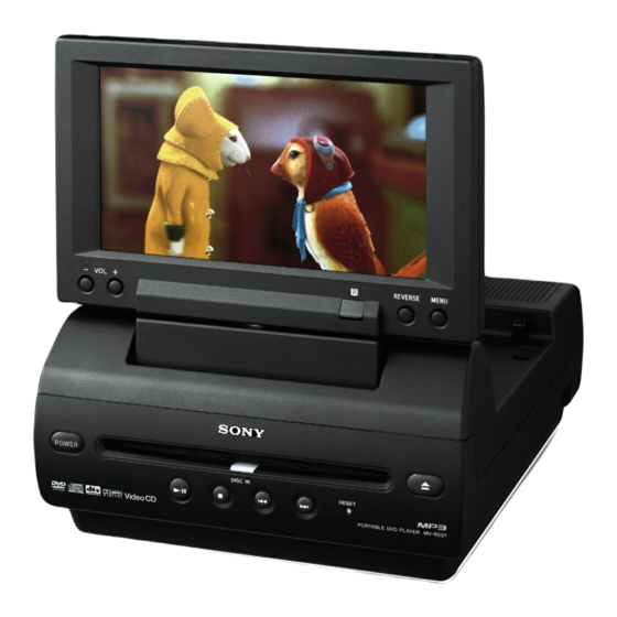
6.5 inches wide screen
(16:9)
280,800 (w 1200 × h 234)
Picture segment
dots
Design and specifications are subject to change
without notice.
PORTABLE DVD PLAYER
E Model
Advertisement
Table of Contents

Related Manuals for Sony MV-65ST


Summary of Contents for Sony MV-65ST
-
Page 1: Specifications
(w/h/d) Mass Approx. 2.3 kg (5 lb 1 oz) Operating temperature 0 ßC to 45 ßC (32 ßF to 113 ßF) PORTABLE DVD PLAYER Sony Corporation 9-877-614-02 2004E05-1 e Vehicle Company © 2004.05 Published by Sony Engineering Corporation... - Page 2 OPERATION. REPLACE THESE COMPONENTS WITH DE FONCTIONNEMENT. NE REMPLACER CES COM- SONY PARTS WHOSE PART NUMBERS APPEAR AS POSANTS QUE PAR DES PIÈCES SONY DONT LES SHOWN IN THIS MANUAL OR IN SUPPLEMENTS PUB- NUMÉROS SONT DONNÉS DANS CE MANUEL OU LISHED BY SONY.
-
Page 3: Table Of Contents
MV-65ST Ver 1.1 SECTION 1 SERVICING NOTES TABLE OF CONTENTS NOTES ON HANDLING THE OPTICAL PICK-UP BLOCK OR BASE UNIT SERVICING NOTES ..........3 The laser diode in the optical pick-up block may suffer electro- static break-down because of the potential difference generated GENERAL by the charged electrostatic load, etc. -
Page 4: General
MV-65ST SECTION 2 This section is extracted from instruction manual. GENERAL Location of controls MV-65ST DI SC IN RE SET Refer to the pages listed for details. qa Speakers (left/right) qs MENU button 1 Monitor To make various display settings and FM 2 VOL −/+ buttons... - Page 5 MV-65ST Card remote commander RM-X137 The corresponding buttons of the card remote commander control the same DISPLAY POWER functions as those on the player. Instructions in this manual describe how to use SEARCH the player by mainly using the card remote CLEAR commander.
- Page 6 MV-65ST This player is supplied with two types of power cable. When you use the player in the car, connect the player to the cigar lighter Optical cable socket; when using at home, connect it to the (not supplied) AC outlet.
-
Page 7: Disassembly
MV-65ST Ver 1.1 SECTION 3 DISASSEMBLY • This set can be disassembled in the order shown below. 3-1. DISASSEMBLY FLOW 3-2. BASE (MONITOR) ASSY (Page 8) 3-3. CABINET (FRONT) ASSY 3-4. MONITOR ASSY (Page 8) (Page 9) 3-8. DVD MD ASSY 3-5. -
Page 8: Base (Monitor) Assy
MV-65ST Note: Follow the disassembly procedure in the numerical order given. 3-2. BASE (MONITOR) ASSY 3 two screws (BVTP3 × 12) 2 Open the monitor 7 base (monitor) assy 6 connector (CN371) 4 three claws 5 terminal 6 two connectors... -
Page 9: Monitor Assy
MV-65ST 3-4. MONITOR ASSY 4 rear cover (hinge) 2 two screws (P2 × 8) 1 Open the monitor. 3 two claws 6 front cover (hinge) 7 four screws 8 monitor assy (PS3 × 10) 5 Close the monitor. -
Page 10: Hinge
MV-65ST 3-5. HINGE 2 five claws 3 rear case (LCD) 2 four claws 4 three connectors (CN904, CN905, CN906) 5 two screws (P2 × 8) 9 LCD bracket hinge 2 four claws q; hinge 1 two screws (B2 × 5) 7 It is half rotation about a hinge. -
Page 11: Liquid Crystal Display Panel (Lcd1)
MV-65ST 3-7. LIQUID CRYSTAL DISPLAY PANEL (LCD1) 2 bracket (LCD) 1 two screws (BTP2 × 6) 6 two retainers (LCD) 5 four screws (BTP2 × 6) 3 two screws (BTP2 × 6) 4 bracket (LCD) 6 two retainers (LCD) 7 insulating sheet (B) -
Page 12: Combo Board, Mechanism Deck
MV-65ST Ver 1.1 3-9. COMBO BOARD, MECHANISM DECK 6 mechanism deck 4 three connectors (J701, J702, J801) 1 FFC-0.5-24 core L70 (CN301) 2 wire (flat type) (CN401) 5 COMBO board 3 two screws (B2.6 × 6) 4 three connectors (J401, J402, J403) 3 two screws (B2.6 ×... -
Page 13: Loading Mechanism Assy
MV-65ST Ver 1.1 3-11. LOADING MECHANISM ASSY 2 loading mechanism assy 1 screw (BTT2 × 4) 3-12. TREVERSE MECHANISM ASSY 7 damper idle 1 two SCW-dampers 2 two SCW-dampers 6 damper idle 4 damper idle q; traverse mechanism assy 5 damper idle... -
Page 14: Test Mode
3. The set is enter the test mode and display as bellow figure. 5. HEAT PROTECTION Display This mode is not used in servicing. MV-65ST TEST MODE MENU 1. NTSC/PAL SELECT 6. LOAD DEFAULT 2. FOR FACTORY 3. LCD SETTING This mode is not used in servicing. -
Page 15: Electrical Adjustments
MV-65ST SECTION 5 ELECTRICAL ADJUSTMENTS DC/DC CONVERTER ADJUSTMENT PLL ADJUSTMENT 1-1. Frequency Adjustment Setting: Setting: digital voltmeter oscilloscope MONITOR board frequency counter TP601 MONITOR board TP602 – TP802 Procedure: TP804 – 1. Connect a digital voltmeter to the TP601 and TP602 on the MONITOR board. - Page 16 MV-65ST − Waveform Position Set-up Adjustment − NTSC SUB CARRIER CHECK 7. Adjust the RV802 on the MONITOR board so that A value of Setting: waveform becomes −2.1 V ±0.1 V. frequency counter MONITOR board 4.9 V ± 0.1 V TP510 A : –...
- Page 17 MV-65ST 2 Back Limiter Level 8 Gamma 1 Procedure: Procedure: 1. In the “1 Contrast Level of Luminance Signal” status, press 1. In the “7 B-ch Sub Contrast” status, connect the oscilloscope Adjustment Location: the [MENU] utton to display “Black Limit”, and press the [RE- to the TP513 and TP811 on the MONITOR board.
-
Page 18: Diagrams
MV-65ST SECTION 6 DIAGRAMS 6-1. BLOCK DIAGRAM – AUDIO Section – CVBS (Page 19) J301 (1/2) J301 (2/2) • R-ch is omitted due to same as L-ch. VIDEO VIDEO • SIGNAL PATH INPUT DIFFERENTIAL OUTPUT : DVD (VIDEO) BUFFER AMP... -
Page 19: Block Diagram - Video, Panel Section
MV-65ST 6-2. BLOCK DIAGRAM – VIDEO, PANNEL Section – LIQUID CRYSTAL DISPLAY MODULE TRAP LCD1 X501 X502 PAL/NTSC SWITCH 3.58MHz 4.43MHz Q504 V COM AMP V COM BIAS VCOM VHG +17V IC802 Q803 – 807 VCOM VDD1 VDD +3.3V VCC +5V... -
Page 20: Block Diagram - Power Section
MV-65ST 6-3. BLOCK DIAGRAM – POWER Section – +3.3V U-COM +3.3V REGULATOR BATT IC952 RESET SIGNAL RESET GENERATOR PANEL +5V REGULATOR IC403 Q402 IC951 S707 RESET D404 BATTERY PW-IN DETECT Q404 PW DET (US, Canadian, Mexican) E-VOL +5V REGULATOR FM-ON... -
Page 21: Note For Printed Wiring Boards And Schematic Diagrams
MV-65ST Ver 1.1 6-4. NOTE FOR PRINTED WIRING BOARDS AND SCHEMATIC DIAGRAMS • Circuit Boards Location Note on Schematic Diagram: Note on Printed Wiring Boards: • All capacitors are in µF unless otherwise noted. pF: µµF 50 WV or • X : parts extracted from the component side. -
Page 22: Printed Wiring Board - Monitor Board (Side A)
MV-65ST 6-5. PRINTED WIRING BOARD – MONITOR Board (Side A) – • See page 21 for Circuit Boards Location. :Uses unleaded solder. POWER BOARD CN902 • Semiconductor (Page 32) POWER BOARD KEY BOARD (Page 32) CN901 CN701 MONITOR BOARD (SIDE A) -
Page 23: Printed Wiring Board - Monitor Board (Side B)
MV-65ST 6-6. PRINTED WIRING BOARD – MONITOR Board (Side B) – • :Uses unleaded solder. See page 21 for Circuit Boards Location. • Semiconductor Location MONITOR BOARD (SIDE B) Ref. No. Location D401 D461 R451 R452 TP513 D501 C-12 R528... -
Page 24: Schematic Diagram - Monitor Board (1/4)
MV-65ST 6-7. SCHEMATIC DIAGRAM – MONITOR Board (1/4) – • See page 35 for Waveforms. • See page 37 for IC Block Diagrams. • See page 42 for IC Pin Function Description. (1/4) R519 R520 4.7k 4.7k D501 R521 R524... -
Page 25: Schematic Diagram - Monitor Board (2/4)
MV-65ST 6-8. SCHEMATIC DIAGRAM – MONITOR Board (2/4) – • See page 35 for Waveforms. • See page 37 for IC Block Diagram. • See page 42 for IC Pin Function Description. T850 (2/4) INVERTER L852 TRANSFORMER TP853 100µH F850... -
Page 26: Schematic Diagram – Monitor Board (3/4)
MV-65ST 6-9. SCHEMATIC DIAGRAM – MONITOR Board (3/4) – • • See page 35 for Waveform. See page 42 for IC Pin Function Description. (Page 24) (Page 25) (3/4) R451 R452 CN905 TP953 CVBS TP954 CVBS GND AMUTE C450 AMUTE D953 UDZS5.6B... -
Page 27: Schematic Diagram - Monitor Board (4/4)
MV-65ST 6-10. SCHEMATIC DIAGRAM – MONITOR Board (4/4) – • • See page 35 for Waveforms. See page 37 for IC Block Diagram. (Page 25) (4/4) C835 C836 R829 C837 R830 4.7k 4.7k CN801 VCOM STH1 SHT1 TP810 GREEN TP811... -
Page 28: Printed Wiring Board - Key Board
MV-65ST Ver 1.1 6-11. PRINTED WIRING BOARD – KEY Board – • See page 21 for Circuit Boards Location. :Uses unleaded solder. KEY BOARD (COMPONENT SIDE) C706 D701 D702, 703 D702 POWER D703 DISC IN R705 1-862-194- (11) KEY BOARD... -
Page 29: Schematic Diagram - Key Board
MV-65ST Ver 1.1 6-12. SCHEMATIC DIAGRAM – KEY Board – CN702 CN301 CN401 (1/2) VFD-CS CN701 UCOM 3.3V TEMP TEMP UCOM 3.3V DA-BE CLK-BE CS-BE KEY A/D KEY PW KEY EJ RESET (Page 26) DISC LED POWER LED KEY GND... -
Page 30: Schematic Diagram - Power Section (1/2)
MV-65ST Ver 1.1 6-13. SCHEMATIC DIAGRAM – POWER Section (1/2) – • • See page 35 for Waveforms. See page 37 for IC Block Diagrams. (US,CND,MX) (1/2) R328 FL301 C324 0.01 CN304 D307 D308 R329 W304 1SS356 1SS356 6.8k TRANSMIT... -
Page 31: Schematic Diagram - Power Section (2/2)
MV-65ST 6-14. SCHEMATIC DIAGRAM – POWER Section (2/2) – • See page 37 for IC Block Diagrams. C371 C275 C276 CN371 1000 10V 1000 C272 R274 C273 R372 R273 Q271 R272 R275 DTC314TU 100k POWER MUTING POWER AMP POWER IC371... -
Page 32: Printed Wiring Board - Power Board (Side A)
MV-65ST Ver 1.1 6-15. PRINTED WIRING BOARD – POWER Board (Side A) – • :Uses unleaded solder. See page 21 for Circuit Boards Location. MONITOR BOARD MONITOR BOARD CN905 CN904 (Page 22) (Page 22) POWER BOARD (SIDE A) (US, CND, MX) -
Page 33: Printed Wiring Board - Power Board (Side B)
MV-65ST Ver 1.1 6-16. PRINTED WIRING BOARD – POWER Board (Side B) – • :Uses unleaded solder. See page 21 for Circuit Boards Location. J801 COMBO BOARD (3/3) POWER BOARD (SIDE B) D905 R929 (US, CND, MX) X301 Q914 R915... -
Page 34: Printed Wiring Board - Amp Section
MV-65ST 6-17. PRINTED WIRING BOARD – AMP Section – • See page 21 for Circuit Boards Location. :Uses unleaded solder. AMPLIFIER BOARD (COMPONENT SIDE) CONNECTOR BOARD (COMPONENT SIDE) W304 CN371 Q372 (11) 1-862-197- R376 Q371 POWER BOARD (Page 32) FB371... - Page 35 MV-65ST • Waveforms – MONITOR Board – 9 IC601 eh (VCO1) qf IC801-1 (Bace) 1 IC501 ts (YIN), tj (CIN) (Color Bars) 3.8 Vp-p 1.5 Vp-p 8.6 Vp-p 4.1 µ s 41 ns 2 IC501 tf (CTRAPIN) (Color Bars) 0 Q857, 858 (Collector) 32 Vp-p 1.2 Vp-p...
- Page 36 MV-65ST – POWER Board – wa IC306 qd (XOUT) 4.3 Vp-p 132 ns ws IC901 7 (OUT1) 11.8 Vp-p 5.1 µ s wd IC901 0 (OUT2) 11.6 Vp-p 5.1 µ s wf Q902, 903 (Emitter) 12 Vp-p 5.1 µ s wg Q905, 906 (Emitter) 11.4 Vp-p...
- Page 37 MV-65ST • IC Block Diagrams – MONITOR Board – IC405 µPD6467GR-546-E1 DISPLAY CONTROL 20 VSYNC DATA REGISTER DATA 19 HSYNC BACK GROUND CONTROL DATA REGISTER 18 VB OUTPUT INSTRUCTION 17 VG DATA INPUT DATA CMDCT SHIFT 1bit x 336 word...
- Page 38 MV-65ST IC501 AN2546FH-AV LOGIC IIC BUS SYNC REGULATOR LOGIC LOGIC SEPARATOR RST 49 LOGIC V SYNC PHASE HHKILL F DET DROP COMP COM DC 50 VCC3 VERTICAL VCOM COMMON OUT COUNT DAC-OUT 51 R-CH AVE DET – SYNC Y-IN 52...
- Page 39 MV-65ST IC801 BA-9743AFV-E2 U.V.L.O. TIMER LATCH TRIANGLE VREF OSCILLATOR VREF VREF ERROR AMP 1 NON1 VREF – INV1 REFERENCE VOLTAGE S.C.P. COMP – PWM COMP1 – ERROR AMP 2 PWM COMP2 NON2 – – INV2 OUT1 GND 8 OUT2 IC850 TL594INSR...
- Page 40 MV-65ST – POWER Board – IC306 BH1415F-E2 IC302 MM1120XFBE VIN2 SW1 2 BUFFER VOUT2 BUFFER VIN1 VOUT1 BIAS RIN2 BUFFER ROUT2 RIN1 BUFFER ROUT1 SHIFT REGISTER LIN2 – BUFFER LOUT2 L. P. F. LIN1 PRE-EMPHASIS BUFFER MUTE & LIMITER L. P. F.
- Page 41 MV-65ST – AMPLIFIER Board – IC371 LA4642 11 10 POP SOUND RIPPLE PROTECTION FILTER BLOCK POWER – PROTECTOR POWER STANDBY SWITCH...
- Page 42 MV-65ST • IC Pin Function Description MONITOR BOARD IC401 µPD780023AGK-C39-9ET (SYSTEM CONTROLLER) Pin No. Pin Name Description TEST Test mode setting terminal “H”: test mode, normally fixed at “L” PW-ON Power on/off control signal output for main power “H”: power on...
- Page 43 MV-65ST Pin No. Pin Name Description KEY HALT Wake up signal input from the POWER and eject key REM HALT Wake up signal input from the remote commander Battery detection signal input when connected AC power adapter (A/D input) PW-IN “L”: battery detect...
- Page 44 MV-65ST MONITOR BOARD IC405 µPD6467GR-546-E1 (OSD DRIVER) Pin No. Pin Name Description SCLK Serial data transfer clock signal input from the system controller Chip select signal input from the system controller DATA Serial data input from the system controller Clear signal input after the power supply rises —...
- Page 45 MV-65ST MONITOR BOARD IC601 MN5814 (LCD CONTROLLER) Pin No. Pin Name Description SYNCIN Composite sync signal input terminal Not used HSYNCIN Horizontal sync signal input from the RGB decoder CPHSEL (SIDE2), 3, 4 Screen size selection signal input from the system controller...
-
Page 46: Exploded Views
MV-65ST Ver 1.1 SECTION 7 EXPLODED VIEWS NOTE: The components identified by • Items marked “*” are not stocked since they • -XX and -X mean standardized parts, so they mark 0 or dotted line with mark 0 are critical for safety. -
Page 47: Cabinet (Front) Section
Part No. Description Remark Ref. No. Part No. Description Remark 3-036-530-02 EMBLEM (NO. 3), SONY 3-262-796-01 BUTTON (MAIN) (u. x. .. >. RESET) X-3384-588-1 CABINET (FRONT) ASSY 3-262-795-01 BUTTON (EJECT) (Z) 3-262-794-01 BUTTON (POWER) 7-685-105-19 SCREW +P 2X8 TYPE2 NON-SLIT... -
Page 48: Base (Monitor) Section
MV-65ST 7-3. BASE (MONITOR) SECTION monitor section not supplied not supplied not supplied not supplied supplied not supplied supplied supplied not supplied not supplied not supplied not supplied Ref. No. Part No. Description Remark Ref. No. Part No. Description Remark... -
Page 49: Monitor Section
MV-65ST 7-4. MONITOR SECTION MONITOR board not supplied not supplied not supplied not supplied not supplied not supplied not supplied LCD1 not supplied not supplied Ref. No. Part No. Description Remark Ref. No. Part No. Description Remark X-3384-586-1 CASE (LCD) ASSY, FRONT... -
Page 50: Cabinet (Lower) Section-1
MV-65ST Ver 1.1 7-5. CABINET (LOWER) SECTION-1 not supplied (AEP, UK, E: PAL TYPE) supplied mechanism deck section-1 cabinet (lower) section-2 Ref. No. Part No. Description Remark Ref. No. Part No. Description Remark A-3283-695-A AMPLIFIER BOARD, COMPLETE 7-685-534-14 SCREW +BTP 2.6X8 TYPE2 N-S 3-223-913-11 LABEL (OP CAUTION) (AEP, UK, E, MX) 7-621-770-67 SCREW +B 2.6X6... -
Page 51: Cabinet (Lower) Section-2
MV-65ST 7-6. CABINET (LOWER) SECTION-2 (including the CONNECTOR board not supplied (US, CND, MX) ) (US, CND, MX) POWER board not supplied not supplied not supplied (CONNECTOR board) not supplied not supplied not supplied (US, CND, MX) not supplied not supplied Ref. -
Page 52: Mechanism Deck Section-1
MV-65ST Ver 1.1 7-7. MECHANISM DECK SECTION-1 mechanism deck section-2 J702 J701 J801 CN301 J401 CN401 J402 J403 Ref. No. Part No. Description Remark Ref. No. Part No. Description Remark 9-885-061-53 COMBO BOARD, COMPLETE * J403 1-564-719-11 PIN, CONNECTOR (SMALL TYPE) 3P... -
Page 53: Mechanism Deck Section-2
MV-65ST Ver 1.1 7-8. MECHANISM DECK SECTION-2 mechanism deck section-3 Ref. No. Part No. Description Remark Ref. No. Part No. Description Remark 9-885-036-31 TD-S-TOP-COVER 9-885-036-22 LOADING MECHANISM ASSY 9-885-036-28 LOADING BELT-L 9-885-036-24 SW BOARD, COMPLETE 9-885-036-43 SCREW (N), M1.7X1.5 9-885-063-32 +BTT 2X4 (S TITE) -
Page 54: Mechanism Deck Section-3
MV-65ST Ver 1.1 7-9. MECHANISM DECK SECTION-3 The components identified by Les composants identifiés par une mark 0 or dotted line with marque 0 sont critiques pour la mark 0 are critical for safety. sécurité. Replace only with part num- Ne les remplacer que par une pièce... -
Page 55: Electrical Parts List
MV-65ST Ver 1.1 SECTION 8 ELECTRICAL PARTS LIST AMPLIFIER COMBO NOTE: • Items marked “*” are not stocked since they • Due to standardization, replacements in the The components identified by mark 0 or dotted line with mark parts list may be different from the parts speci- are seldom required for routine service. - Page 56 MV-65ST CONNECTOR MONITOR Ref. No. Part No. Description Remark Ref. No. Part No. Description Remark CONNECTOR BOARD (US, CND, MX) C411 1-162-918-11 CERAMIC CHIP 18PF C450 1-107-826-11 CERAMIC CHIP 0.1uF ***************** (included in the POWER board) C460 1-126-396-11 ELECT CHIP...
- Page 57 MV-65ST MONITOR Ref. No. Part No. Description Remark Ref. No. Part No. Description Remark C547 1-162-915-11 CERAMIC CHIP 10PF 0.5PF C843 1-107-826-11 CERAMIC CHIP 0.1uF C604 1-126-396-11 ELECT CHIP 47uF C844 1-127-820-11 CERAMIC CHIP 4.7uF C605 1-107-826-11 CERAMIC CHIP 0.1uF...
- Page 58 MV-65ST MONITOR Ref. No. Part No. Description Remark Ref. No. Part No. Description Remark D853 6-500-086-01 DIODE RLS4148TE-11 L806 1-456-440-21 INDUCTOR 47uH D950 8-719-044-76 DIODE 1SS356-TW11 L807 1-456-440-21 INDUCTOR 47uH D951 8-719-069-55 DIODE UDZSTE-175.6B L808 1-410-381-11 INDUCTOR 10uH D952 8-719-069-55 DIODE UDZSTE-175.6B...
- Page 59 MV-65ST MONITOR Ref. No. Part No. Description Remark Ref. No. Part No. Description Remark R408 1-216-809-11 METAL CHIP 1/10W R411 1-216-809-11 METAL CHIP 1/10W R470 1-216-833-11 METAL CHIP 1/10W R412 1-216-809-11 METAL CHIP 1/10W R480 1-216-817-11 METAL CHIP 1/10W R481...
- Page 60 MV-65ST MONITOR Ref. No. Part No. Description Remark Ref. No. Part No. Description Remark R610 1-216-821-11 METAL CHIP 1/10W R611 1-216-837-11 METAL CHIP 1/10W R817 1-216-840-11 METAL CHIP 1/10W R612 1-216-837-11 METAL CHIP 1/10W R829 1-216-829-11 METAL CHIP 4.7K 1/10W...
- Page 61 MV-65ST MONITOR POWER Ref. No. Part No. Description Remark Ref. No. Part No. Description Remark R956 1-216-833-11 METAL CHIP 1/10W R957 1-216-833-11 METAL CHIP 1/10W C203 1-165-884-11 CERAMIC CHIP 2.2uF 6.3V R958 1-216-845-11 METAL CHIP 100K 1/10W C204 1-165-884-11 CERAMIC CHIP 2.2uF...
- Page 62 MV-65ST POWER Ref. No. Part No. Description Remark Ref. No. Part No. Description Remark C335 1-125-837-11 CERAMIC CHIP 6.3V C930 1-164-315-11 CERAMIC CHIP 470PF (US, CND, MX) C931 1-162-970-11 CERAMIC CHIP 0.01uF C336 1-126-096-11 ELECT 10uF C932 1-117-863-11 CERAMIC CHIP 0.47uF...
- Page 63 MV-65ST POWER Ref. No. Part No. Description Remark Ref. No. Part No. Description Remark < JACK/IC > Q914 8-729-026-52 TRANSISTOR 2SA1576A-T106-R J301 1-818-523-11 JACK, PIN (VIDEO/AUDIO INPUT/OUTPUT) < RESISTOR > J302 8-749-016-00 IC HVE0024 (OPTICAL OUTPUT) J901 1-793-459-21 JACK, DC (POLARITY UNIFIED TYPE)
- Page 64 MV-65ST POWER Ref. No. Part No. Description Remark Ref. No. Part No. Description Remark R304 1-216-821-11 METAL CHIP 1/10W R348 1-216-837-11 METAL CHIP 1/10W R306 1-218-285-11 METAL CHIP 1/10W (US, CND, MX) R307 1-216-809-11 METAL CHIP 1/10W R349 1-216-841-11 METAL CHIP...
- Page 65 MV-65ST Ver 1.1 POWER SENSOR Ref. No. Part No. Description Remark Ref. No. Part No. Description Remark R931 1-216-841-11 METAL CHIP 1/10W PARTS FOR INSTALLATION AND CONNECTIONS ************************************** R932 1-216-837-11 METAL CHIP 1/10W R934 1-216-033-00 RES-CHIP 1/10W 0 501 1-827-480-11 POWER-SUPPLY CORD (AEP, UK)
-
Page 66: Revision History
MV-65ST REVISION HISTORY Clicking the version allows you to jump to the revised page. Also, clicking the version at the upper right on the revised page allows you to jump to the next revised page. Ver. Date Description of Revision 2004.03...