Table of Contents
Advertisement
Advertisement
Table of Contents

Related Manuals for ABB ACS255


Summary of Contents for ABB ACS255
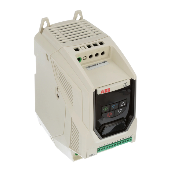
- Page 1 ABB Micro drives User’s manual ACS255 drives (0.5…20 hp) (600V Variants)
- Page 2 List of related manuals Option manuals and guides Code (English) ACS255 user’s manual for 115-480V variants 3AXD10000528266...
- Page 3 ACS255 drives 0.5…20 hp User’s manual 3AXD10000528265 Rev A EFFECTIVE: 2016-09-13 © 2016 ABB Oy. All Rights Reserved.
-
Page 4: Table Of Contents
Table of Contents ACS255 – IP20 (600V Variants) EASY START-UP GUIDE ________________________________________ 7 ACS255 – IP66 (600V Variants) EASY START-UP GUIDE ________________________________________ 8 Safety ____________________________________________________________________________ 10 What this chapter contains _____________________________________________________________________ 10 Use of warnings ______________________________________________________________________________ 10 Safety in installation and maintenance ____________________________________________________________ 10... - Page 5 6.3. Resetting Parameters to Factory Default Settings _____________________________________________ 29 6.4. Advanced Keypad Operation ShortCuts _____________________________________________________ 30 6.5. Drive Operating Displays ________________________________________________________________ 30 Quick Start-up and Control ___________________________________________________________ 31 7.1. Quick Start-up Terminal Control __________________________________________________________ 31 7.2. Quick Start-up Keypad Control ____________________________________________________________ 31 7.3.
-
Page 6: Easy Start-Up Guide
ACS255 – IP20 (600V Variants) EASY START-UP GUIDE P20 Easy Start AC Supply Connection Supply Voltage 3 Phase : Connect L1 L2 L3, PE 500-600 Volts + / - 10% Fuses Fuses or MCB Fuse rating recommendation values given on page 59... -
Page 7: Acs255 - Ip66 (600V Variants) Easy Start-Up Guide
ACS255 – IP66 (600V Variants) EASY START-UP GUIDE Display Keypad Operation can be found In Section 6 and 7.2. IMPORTANT HARDWARE ENABLE 12 13 Link the terminals as shown Above, optionally through switch contacts to enable the drive Control Terminals... - Page 8 Declaration of Conformity: ABB Drives Ltd hereby states that the ACS255 product range conforms to the relevant safety provisions of the following council directives: 2014/30/EU (EMC) and 2014/35/EU (LVD) 2011/65/EU (RoHS) EN 61800-5-1: 2007 Adjustable speed electrical power drive systems. Safety requirements. Electrical, thermal and energy.
-
Page 9: Safety
2. Safety What this chapter contains This chapter contains the safety instructions which you must follow when installing, operating and servicing the drive. If ignored, physical injury or death may follow, or damage may occur to the drive, motor or driven equipment. Read the safety instructions before you work on the unit. -
Page 10: Safety In Start-Up And Operation
WARNING! Ignoring the following instructions can cause physical injury or death, or damage to the equipment. The drive is not field repairable. Never attempt to repair a malfunctioning drive; contact your local ABB representative or Authorized Service Centre for replacement. - Page 11 Ensure that all terminals are tightened to the appropriate torque setting Do not attempt to carry out any repair of the ACS255. In the case of suspected fault or malfunction, contact your local ABB Drives representative for further assistance.
-
Page 12: General Information And Ratings
The type designation contains information on the specification and configuration of the drive. You find the type designation label attached to the drive. The first digits from the left express the basic configuration, for example ACS255-03U-02A1-6. The explanations of the type designation label selections are described below. -
Page 13: Drive Model Numbers - Ip20
Internal DB transistor Frame Size (HP) assembly ACS255-03U-02A1-6 +B063 ACS255-03U-03A1-6 +B063 ACS255-03U-04A1-6 +B063 ACS255-03U-06A5-6 +B063 ACS255-03U-09A0-6 +B063 ACS255-03U-12A0-6 +B063 ACS255-03U-17A0-6 +B063 ACS255-03U-02A1-6 +B063 +F278 ACS255-03U-03A1-6 +B063 +F278 ACS255-03U-04A1-6 +B063 +F278 ACS255-03U-06A5-6 +B063 +F278 ACS255-03U-09A0-6 +B063 +F278 ACS255-03U-12A0-6 +B063 +F278 ACS255-03U-17A0-6 +B063 +F278... -
Page 14: Mechanical Installation
Check the drive rating label to ensure it is of the correct type and power requirements for the application. To prevent accidental damage always store the ACS255 in its original box until required. Storage should be clean and dry and within the temperature range –40°C to +60°C. - Page 15 4.4.2. IP66 Units Drive Weight Size 10.12 8.66 7.87 9.41 7.40 6.93 0.17 0.33 10.6 12.20 10.89 9.90 9.88 8.29 7.78 0.17 0.33 16.1 Mounting Bolt Sizes All Frame Sizes 4 x M4 Tightening Torques Recommended Control Terminal Torque Settings :All Sizes : 0.8 Nm (7 lb-in) Recommended Power Terminal Torque Settings : Frame Size 2 : 1.2 –...
-
Page 16: Guidelines For Enclosure Mounting (Ip20 Units)
In any environments where the conditions require it, the enclosure must be designed to protect the ACS255 against ingress of airborne dust, corrosive gases or liquids, conductive contaminants (such as condensation, carbon dust, and metallic particles) and sprays or splashing water from all directions. -
Page 17: Guidelines For Mounting (Ip66 Units)
4.7. Guidelines for mounting (IP66 Units) Before mounting the drive, ensure that the chosen location meets the environmental condition requirements for the drive shown in section 11.1. The drive must be mounted vertically, on a suitable flat surface ... -
Page 18: Electrical Installation
This ACS255 contains high voltage capacitors that take time to discharge after removal of the main supply. Before working on the drive, ensure isolation of the main supply from line inputs. Wait ten (10) minutes for the capacitors to discharge to safe voltage levels. -
Page 19: Wiring Precautions
The ground terminal of each ACS255 should be individually connected DIRECTLY to the site ground bus bar (through the filter if installed). The ACS255 ground connections should not loop from one drive to another, or to, or from any other equipment. Ground loop impedance must confirm to local industrial safety regulations. -
Page 20: Compatibility With It (Ungrounded) And Corner-Grounded Tn Systems
5.4. Compatibility with IT (ungrounded) and corner-grounded TN systems WARNING! EMC filters should not be used when installing the drive on an IT system (an ungrounded power system or high-resistance-grounded power system, otherwise the system will be connected to ground potential through the EMC capacitors. This may cause danger or damage to the EMC filter. If you have an IT (ungrounded) system or corner-grounded TN system, disconnect the internal Varistor screw as shown below. -
Page 21: Drive And Motor Connection
The motor should be connected to the ACS255 U, V, and W terminals using a suitable 3 or 4 core cable. Where a 3 core cable is utilised, with the shield operating as an earth conductor, the shield must have a cross sectional area at least equal to the phase conductors when they are made from the same material. -
Page 22: Connection Diagram
5.9. Connection Diagram 5.9.1. Power Terminal Designations Incoming Power Source Motor Connections Connect to L1, L2 & L3 Connect the motor to the U, V & W terminals. terminals. Phase sequence is not The motor earth must be connected important. to the drive Optional Brake Resistor &... -
Page 23: Safe Torque Off
5.10. Safe Torque Off Safe Torque OFF will be referred to as “STO” through the remainder of this section. 5.10.1. Responsibilities The overall system designer is responsible for defining the requirements of the overall “Safety Control System” within which the drive will be incorporated;... - Page 24 Number A fault has been detected within either of the “Sto-F” Refer to local ABB representative internal channels of the “STO” circuit. 5.10.6. “STO” Function response time The total response time is the time from a safety related event occurring to the components (sum of) within the system responding and becoming safe.
- Page 25 5.10.7. “STO” Electrical Installation The “STO” wiring shall be protected from inadvertent short circuits or tampering which could lead to failure of the “STO” input signal, further guidance is given in the diagrams below. In addition to the wiring guidelines for the “STO” circuit below, section 5.1.1 “Recommended installation for EMC compliance should also be followed.
- Page 26 5.10.8. Enabling the “STO” Function The “STO” function is always enabled in the drive regardless of operating mode or parameter changes made by the user 5.10.9. Testing the “STO” Function Before commissioning the system the “STO” function should always be tested for correct operation, this should include the following tests: ...
-
Page 27: Managing The Keypad
6. Managing the Keypad The drive is configured and its operation monitored via the keypad and display. 6.1. Keypad Layout and Function Used to display real-time information, to access and exit NAVIGATE parameter edit mode and to store parameter changes (press for >1 second to toggle between status and parameter mode) Used to increase speed in real-time mode or to increase parameter values in parameter edit mode... -
Page 28: Resetting Parameters To Factory Default Settings
6.3. Resetting Parameters to Factory Default Settings... -
Page 29: Advanced Keypad Operation Shortcuts
6.4. Advanced Keypad Operation ShortCuts Function When Display shows... Press... Result Example Display shows Press Select lowest Parameter The first parameter of the i.e. within Group group is selected Display shows When editing Display shows Press... -
Page 30: Quick Start-Up And Control
7. Quick Start-up and Control 7.1. Quick Start-up Terminal Control When delivered, the ACS255 is in the factory default state, meaning that it is set to operate in terminal control mode and all parameters have the default values as indicated in section 9. -
Page 31: Sensorless Vector Speed Control Mode
7.3. Sensorless Vector Speed Control Mode ACS255 can be programmed by the user to operate in Sensorless Vector mode, which provides enhanced low speed torque, optimum motor speed regulation regardless of load and accurate control of the motor torque. In most applications, the default Voltage Vector control mode will provide adequate performance, however if Sensorless Vector operation is required, use the following procedure. -
Page 32: Application Macros
8. Application Macros 8.1. Overview of macros Application macros are pre-programmed parameter sets. While starting up the drive, the user selects the macro best suited for the purpose with parameter 9902 DIGITAL INPUTS FUNCTION SELECT and 1103 PRIMARY COMMAND SOURCE MODE. The term “Selected Speed Reference”... -
Page 33: Macro Wiring Configurations
Digital Input 1 Digital Input 2 Digital Input 3 Analog Input 1 Analog Input 2 9902 (Terminal 2) (Terminal 3) (Terminal 4) (Terminal 6) (Terminal 10) Digital input 3 Analog input 1 Preset Speed Preset Speed 1 O: Stop O: Stop O: Selected Speed Ref Preset Speed 2 C: Run Fwd... - Page 34 9902 = 5 Open Closed 9902 = 6 Open Closed +24 Volt Common +24 Volt Common Stop Stop Forward Rotation Reverse Rotation Forward Rotation Reverse Rotation Selected Speed ref Analog input 2 speed ref Selected Speed ref Preset Speed 1 (1202) +10 Volt +10 Volt Analog Input 1...
- Page 35 9902 = 1 1 Open Closed 9902 = 12 Open Closed +24 Volt Common +24 Volt Common Stop Run Forward Stop Run Forward Stop Run Reverse Stop Run Reverse Selected Speed ref Preset Speed ref +10 Volt Preset Open Open Open 1202 Analog Input 1...
- Page 36 9902 = 17 Open Closed 9902 = 18 Open Closed +24 Volt Common +24 Volt Common Stop Run Forward Stop Run Forward Stop Run Reverse Stop Run Reverse Preset Preset Open Open 1202 Open Open 1202 Closed Open 1203 Closed Open 1203 Open...
-
Page 37: Parameters
Parameter No. Parameter No. 9902 0000 0401 9905 1100 9906 1103 9907 1202 0401 1203 1103 1204 1202 ABB Short parameter group 1205 (1611 not set to "101") 1203 1204 1301 3400 2008 4001 2102 4002 2202 4005 4010 4011 4016... -
Page 38: Parameters In The Short Parameter Mode
9.2. Parameters in the Short parameter mode The following table describes the parameters that are visible in the Short parameter mode. See section 9.1 on page 38 for how to select the parameter mode. All parameters are presented in detail in section Parameters in the Long parameter mode. Parameters in the Short parameter mode Name/Value Description... - Page 39 2 : Ramp To Stop When the enable signal is removed, the drive will ramp to stop, with the rate controlled by Parameter 2203 DECEL RAMP TIME as described above. The ACS255 Brake chopper is also enabled in this mode.
-
Page 40: Read Only Status Parameters
0188 OPERATING TIME Displays the amount of time in hours and minutes that the ACS255 has operated for during its lifetime ACCUMULATED WITH with a heatsink temperature in excess of 80°C. This parameter is used by the ACS255 for various HEATSINK TEMPERATURE internal protection and monitoring functions. - Page 41 0189 OPERATING TIME Displays the amount of time in hours and minutes that the ACS255 has operated for during its lifetime ACCUMULATED WITH AMBIENT with an ambient temperature in excess of 80°C. This parameter is used by the ACS255 for various TEMPERATURE ABOVE 80°C...
-
Page 42: Parameters In The Long Parameter Mode
3 : PRESET SPEED 4 Following a stop and restart, the ACS255 will always initially run at Preset Speed 4 (Par 1205) 4 : MINIMUM SPEED Following a stop and restart, the drive will always initially run at the minimum speed (TERMINAL ENABLE) parameter 2007 MIN SPEED LIMIT. - Page 43 3mA 4 to 20mA Signal, the ACS255 will ramp to stop if the signal level falls below 3 mA 20 to 4mA Signal, the ACS255 will trip and show the fault code...
- Page 44 Parameters in the Long parameter mode Index Name/Selection Description 1305 ANALOG INPUT 2 OFFSET Sets an offset, as a percentage of the full scale range of the input, which is applied to the 0.0% analog input signal -500…500 % Value in percent of the full scale range of the input Example: If the analog input signal format is 0-10V, offset = 20% .
- Page 45 Logic 0 when the signal falls below the value programmed in 3202 ADJUSTABLE THRESHOLD 1 LOWER LIMIT. 0 : DRIVE ENABLED Logic 1 when the ACS255 is enabled (Running) (RUNNING) 1: DRIVE READY Logic 1 When no Fault condition exists on the drive...
- Page 46 Logic 0 when the signal falls below the value programmed in 3202 ADJUSTABLE THRESHOLD 1 LOWER LIMIT. 0 : DRIVE ENABLED Logic 1 when the ACS255 is enabled (Running) (RUNNING) 1: DRIVE READY Logic 1 When no Fault condition exists on the drive...
- Page 47 0.0% TORQUE LIMIT MODE = 0 or 1). Sets a minimum torque limit, whereby when the ACS255 is enabled, it will always attempt to maintain this torque on the motor at all times whilst operating. WARNING : This parameter should be used with extreme care, as the drive output frequency will increase to achieve the torque level, and may exceed the selected speed reference.
- Page 48 2 : RAMP TO STOP When the enable signal is removed, the drive will ramp to stop, with the rate controlled by Parameter 2203 DECEL RAMP TIME as described above. The ACS255 Brake chopper is also enabled in this mode.
- Page 49 0.00 TIME the ACS255, which can be selected by digital inputs (dependent on the setting of Parameter 9902 DIGITAL INPUTS FUNCTION SELECT or selected automatically in the case of a mains power loss if parameter 2006 MAINS LOSS RIDE THROUGH / STOP CONTROL = 2.
- Page 50 Sets the watchdog time period for the communications channel. If a valid telegram is not TIMEOUT received by the ACS255 within this time period, the drive will assume a loss of communications has occurred and react as selected below. Setting to zero disables the function.
- Page 51 33 INFORMATION Firmware update. 3399 FIRMWARE UPGRADE ABB Internal use only. 34 PANEL DISPLAY Selection of actual signals to be displayed on the drives front panel e.g. to display conveyer speed in feet per second based on the output frequency...
- Page 52 Entering the value from the motor nameplate enables the slip compensation function, and the ACS255 display will now show motor speed in estimated rpm. All speed related parameters, such as Minimum and Maximum Speed, Preset Speeds etc.
-
Page 53: Preventing Un-Authorized Parameter Editing
Parameters in the Long parameter mode Index Name/Selection Description 112 Vector mode advanced motor Only valid when parameter 9903 Motor Control Mode is 0,1, 3. data WARNING! The following parameters are used internally by the drive to provide optimum possible motor control. Incorrect setting of the parameters can result in poor performance and unexpected behaviour of the motor. -
Page 54: Serial Communications
10.1. RJ45 Connector Pin Assignment ACS255 has an RJ45 connector on the front of the control panel. This connector allows the user to set up a drive network via a wired connection. The connector contains multiple interfaces for different communication protocols. - Page 55 Modbus RTU supports sixteen bit integer values, hence where a decimal point is used in the drive parameter; the register value will be multiplied by a factor of ten, E.g. Read Value of parameter 2008 = 500, therefore this is 50.0Hz. For further details on communicating with ACS255 using Modbus RTU, please refer to your local ABB representative.
- Page 56 ADJUSTABLE THRESHOLD 1 UPPER LIMIT (ANALOG OUTPUT 1/RELAY OUTPUT 1) 3205 ADJUSTABLE THRESHOLD 1 LOWER LIMIT (ANALOG OUTPUT 1/RELAY OUTPUT 2) 3206 ADJUSTABLE THRESHOLD 1 UPPER LIMIT (ANALOG OUTPUT 1/RELAY OUTPUT 2) 3399 FIRMWARE UPGRADE (ABB INTERNAL USE ONLY) 3400 DISPLAY SPEED SCALING FACTOR 3405 DISPLAY SCALING SOURCE 4001...
- Page 57 Register No Parameter No Description PI DIGITAL REFERENCE (SETPOINT) 4011 PI FEEDBACK SIGNAL SOURCE SELECT 4016 ENERGY CONSUMPTION METER 4509 DRIVE FIELDBUS ADDRESS 5302 5303 MODBUS RTU BAUD RATE MODBUS DATA FORMAT 5304 CANOPEN BAUD RATE 5305 9902 DIGITAL INPUTS FUNCTION SELECT MOTOR CONTROL MODE 9903 9905...
-
Page 58: Technical Data
The PWM output switching from any inverter when used with a long motor cable length can cause an increase in the voltage at the motor terminals, depending on the motor cable length and inductance. The rise time and peak voltage can affect the service life of the motor. ABB Drives recommend using an output choke for motor cable lengths of 50m or more to ensure good motor service life ... -
Page 59: Additional Information For Ul Approved Installations
Amperes symmetrical with the specified maximum supply voltage. Incoming power supply connection must be according to section 5.9 All ACS255 units are intended for indoor installation within controlled environments which meet the condition limits shown in section 11.1 on page 59. -
Page 60: Appendix: Permanent Magnet Synchronous Motors (Pmsms)
12. Appendix: Permanent magnet synchronous motors (PMSMs) With PMSMs special attention must be paid on setting the motor nominal values correctly in parameter group 99 START-UP DATA. It is important that the nominal back-emf of the motor is available, further to ensure good performance a MOTOR PARAMETER AUTO-TUNE (9910=1) must be performed. -
Page 61: Troubleshooting
13. Troubleshooting 13.1. Fault messages Fault Code Description Corrective Action No Fault Displayed in Parameter 0401 if no faults are recorded in the log Brake channel over current Ensure the connected brake resistor is above the minimum permissible level for the drive – refer to the ratings shown in section 11.2. - Page 62 4-20mA Signal Lost The reference signal on Analog Input 1 or 2 (Terminals 6 or 10) has dropped below the minimum threshold of 3mA. Check the signal source and wiring to the ACS255 terminals. Internal memory fault. Parameters not saved, defaults reloaded.