Table of Contents
Advertisement
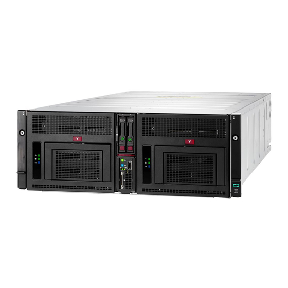
HPE Apollo 4510 Gen10 Chassis
Maintenance and Service Guide
Abstract
This guide describes identification and maintenance procedures, diagnostic tools,
specifications for hardware components, and software for the HPE Apollo 4500 Systems. This
guide is for an experienced service technician. Hewlett Packard Enterprise assumes you are
qualified in the servicing of computer equipment, trained in recognizing hazards in products,
and are familiar with weight and stability precautions.
Part Number: 881304-001
Published: October 2017
Edition: 1
Advertisement
Table of Contents

Related Manuals for HP Apollo 4510 Gen10


Summary of Contents for HP Apollo 4510 Gen10
- Page 1 HPE Apollo 4510 Gen10 Chassis Maintenance and Service Guide Abstract This guide describes identification and maintenance procedures, diagnostic tools, specifications for hardware components, and software for the HPE Apollo 4500 Systems. This guide is for an experienced service technician. Hewlett Packard Enterprise assumes you are qualified in the servicing of computer equipment, trained in recognizing hazards in products, and are familiar with weight and stability precautions.
- Page 2 © Copyright 2017 Hewlett Packard Enterprise Development LP Notices The information contained herein is subject to change without notice. The only warranties for Hewlett Packard Enterprise products and services are set forth in the express warranty statements accompanying such products and services. Nothing herein should be construed as constituting an additional warranty. Hewlett Packard Enterprise shall not be liable for technical or editorial errors or omissions contained herein.
-
Page 3: Table Of Contents
Contents Illustrated parts catalog................6 Mechanical components....................... 6 Drive drawer rail spare parts....................6 Midplane assembly cover spare parts................7 Fan cage louver spare part....................7 Power supply blank spare part...................7 4U rack mounting kit spare parts..................7 Drive blank spare part......................7 Drive drawer cable track spare part................... - Page 4 Removing and replacing a midplane assembly................38 Removing and replacing a fan louver..................40 Removing and replacing the drive drawer assembly..............40 Removing and replacing the chassis lift handles................ 45 Troubleshooting..................47 Troubleshooting resources......................47 Diagnostic tools..................48 Product QuickSpecs........................48 UEFI System Utilities........................
- Page 5 Hot-plug power supply calculations.................... 73 Documentation feedback..............74 Contents...
-
Page 6: Illustrated Parts Catalog
Illustrated parts catalog Mechanical components Hewlett Packard Enterprise continually improves and changes product parts. For complete and current supported parts information, see the Hewlett Packard Enterprise PartSurfer website (http:// www.hpe.com/info/partssurfer). Item Description Drive drawer rail spare parts on page 6 Midplane assembly cover spare parts on page 7 Fan cage louver spare part on page 7 Power supply blank spare part on page 7... -
Page 7: Midplane Assembly Cover Spare Parts
Midplane assembly cover spare parts Customer self repair on page 15: mandatory Description Spare part number Midplane assembly cover 880981-001 Fan cage louver spare part Customer self repair on page 15: mandatory Description Spare part number Fan cage louver 880987-001 Power supply blank spare part Customer self repair on page 15: mandatory Description... -
Page 8: System Components
System components Hewlett Packard Enterprise continually improves and changes product parts. For complete and current supported parts information, see the Hewlett Packard Enterprise PartSurfer website (http:// www.hpe.com/info/partssurfer). All processors in this HPE ProLiant server must have the same cache size, speed, number of cores, and rated maximum power consumption. -
Page 9: Cable Retention Bracket Spare Part
Cable retention bracket spare part Customer self repair on page 15: mandatory Description Spare part number Cable retention bracket 880989-001 Midplane assembly spare parts Customer self repair on page 15: optional Description Spare part number Midplane assembly (1x60) 880990-001 Management module spare part Customer self repair on page 15: optional Description Spare part number... -
Page 10: Cable Kit Spare Parts
Cable kit spare parts Customer self repair on page 15: mandatory Description Spare part number Midplane - fan cable kit 879509-001 Front I/O/USB cable kit 879510-001 HPE Apollo 4510 E208i-p/P408i-p Mini SAS cable 879037-001 HPE Smart Array cable kit (P408i-a/E208i-a) 879038-001 Chassis options Hewlett Packard Enterprise continually improves and changes product parts. - Page 11 Description Spare part number HPE 480 GB SATA MU LFF LPC DS SSD 879015-001 HPE 960 GB SATA RI LFF LPC DS SSD 878851-001 HPE 960 GB SATA MU LFF LPC DS SSD 879018-001 HPE 1 TB SATA 7.2K LFF LP DS HDD 862130-001 HPE 1.6 TB SATA RI LFF LPC SSD 841481-001...
-
Page 12: Hpe Smart Storage Battery Spare Part
Description Spare part number HPE 4 TB SAS 7.2K LFF LP DS HDD 834134-001 HPE 6 TB SAS 7.2K LFF LP 512e HDD 862136-001 HPE 6 TB SAS 7.2K LFF LP DS HDD 846611-001 HPE 7.68 TB SAS 12G RI LFF-LPc DS SSD 870461-001 HPE 8 TB SAS 7.2K LFF LP He 512e DS HDD 861608-001... - Page 13 Description Spare part number HPE SN1600E 32Gb 2p FC Host Bus Adapter 870000-001 HPE SN1200E 16Gb 1p FC Host Bus Adapter 870001-001 HPE SN1200E 16Gb 2p FC Host Bus Adapter 870002-001 Table 3: Network controllers Description Spare part number HPE Ethernet 1Gb 2P 332T Adapter 616012-001 HPE Ethernet 1Gb 4-port 331T Adapter 649871-001...
-
Page 14: Chassis Lift Handle Spare Parts
Description Spare part number HPE Ethernet 10Gb 2p 522FLR-T Converged 869571-001 Network Adapter HPE Ethernet 10/25Gb 2p 622FLR-SFP28 869572-001 Converged Network Adapter Table 5: Infiniband adapters Description Spare part number HPE IB EDR 100Gb 1p 841QSFP28 adapter 878578-001 Infiniband Fourteen Data Rate (FDR)/Ethernet 764736-001 10Gb/40Gb two port 544+ Quad Small Form-factor Pluggable (QSFP) adapter... -
Page 15: Customer Self Repair
Customer self repair Hewlett Packard Enterprise products are designed with many Customer Self Repair (CSR) parts to minimize repair time and allow for greater flexibility in performing defective parts replacement. If during the diagnosis period Hewlett Packard Enterprise (or Hewlett Packard Enterprise service providers or service partners) identifies that the repair can be accomplished by the use of a CSR part, Hewlett Packard Enterprise will ship that part directly to you for replacement. - Page 16 • Obligatoire—Pièces pour lesquelles la réparation par le client est obligatoire. Si vous demandez à Hewlett Packard Enterprise de remplacer ces pièces, les coûts de déplacement et main d'œuvre du service vous seront facturés. • Facultatif—Pièces pour lesquelles la réparation par le client est facultative. Ces pièces sont également conçues pour permettre au client d'effectuer lui-même la réparation.
- Page 17 un centro di assistenza autorizzato. Tali parti sono identificate da un "No" nel Catalogo illustrato dei componenti. In base alla disponibilità e alla località geografica, le parti CSR vengono spedite con consegna entro il giorno lavorativo seguente. La consegna nel giorno stesso o entro quattro ore è offerta con un supplemento di costo solo in alcune zone.
- Page 18 Ersatzteil in Rechnung stellen. Im Falle von Customer Self Repair kommt Hewlett Packard Enterprise für alle Kosten für die Lieferung und Rücksendung auf und bestimmt den Kurier-/Frachtdienst. Weitere Informationen über das Hewlett Packard Enterprise Customer Self Repair Programm erhalten Sie von Ihrem Servicepartner vor Ort.
- Page 19 Servicio de garantía exclusivo de componentes La garantía limitada de Hewlett Packard Enterprise puede que incluya un servicio de garantía exclusivo de componentes. Según las condiciones de este servicio exclusivo de componentes, Hewlett Packard Enterprise le facilitará los componentes de repuesto sin cargo adicional alguno. Para este servicio de garantía exclusivo de componentes, es obligatoria la sustitución de componentes por parte del usuario (CSR).
- Page 20 Voor de Parts Only garantieservice is vervanging door CSR-onderdelen verplicht. Als u Hewlett Packard Enterprise verzoekt deze onderdelen voor u te vervangen, worden u voor deze service reiskosten en arbeidsloon in rekening gebracht Reparo feito pelo cliente Os produtos da Hewlett Packard Enterprise são projetados com muitas peças para reparo feito pelo cliente (CSR) de modo a minimizar o tempo de reparo e permitir maior flexibilidade na substituição de peças com defeito.
- Page 21 Customer self repair...
- Page 22 Customer self repair...
- Page 23 Customer self repair...
-
Page 24: Removal And Replacement Procedures
Removal and replacement procedures This chapter provides detailed instructions on how to remove and replace component spare parts. Required tools The following tools might be required to perform some procedures: • T-10 Torx screwdriver • T-15 Torx screwdriver • HPE Insight Diagnostics software Preparation procedures To access some components and perform certain service procedures, you must perform one or more of the following procedures:... -
Page 25: Extend The Drive Drawer From The Chassis
This method forces the server to enter standby mode without properly exiting applications and the OS. If an application stops responding, you can use this method to force a shutdown. • Use a virtual power button selection through iLO. This method initiates a controlled remote shutdown of applications and the OS before the server enters standby mode. -
Page 26: Remove The Chassis From The Rack
Remove the chassis from the rack WARNING: The chassis is very heavy. To reduce the risk of personal injury or damage to the equipment: • Observe local occupational health and safety requirements and guidelines for manual material handling. • Remove all installed components from the chassis before installing or moving the chassis. •... -
Page 27: Remove The Server From The Chassis
8. Remove the chassis from the rack. 9. Place the chassis on a flat, sturdy surface to support the chassis. Remove the server from the chassis CAUTION: Before removing the server, verify that the server backup LED is not flashing. Procedure 1. -
Page 28: Safety Considerations
NOTE: To avoid damage to the device, do not use the removal handle to carry it. 3. Place the server on a flat, level work surface. Safety considerations Before performing service procedures, review all the safety information. Preventing electrostatic discharge To prevent damaging the system, be aware of the precautions you must follow when setting up the system or handling parts. -
Page 29: System Warnings And Cautions
This symbol indicates the presence of electric shock hazards. The area contains no user or field serviceable parts. Do not open for any reason. WARNING: To reduce the risk of injury from electric shock hazards, do not open this enclosure. This symbol on an RJ-45 receptacle indicates a network interface connection. -
Page 30: Removing And Replacing The Bezel Ear
Removing and replacing the bezel ear Procedure 1. Power down the server on page 24. 2. Remove the bezel ear. To replace the component, reverse the removal procedure. Removing and replacing the management module CAUTION: To avoid loss of data, back up all data and power down the node before removing the management module. -
Page 31: Removing And Replacing The I/O Module
To replace the component, reverse the removal procedure. Removing and replacing the I/O module Procedure 1. Power down the server on page 24. 2. Disconnect any cables connected to the I/O module. 3. Remove the I/O module. To replace the component, reverse the removal procedure. Removing and replacing the I/O module... -
Page 32: Removing And Replacing An Expansion Board
Removing and replacing an expansion board Procedure 1. Remove the I/O module (Removing and replacing the I/O module on page 31). 2. Disconnect the cables connected to the expansion board option. 3. Remove the support bracket from the I/O module. 4. -
Page 33: Removing And Replacing A Power Supply
To replace the component, reverse the removal procedure. Removing and replacing a power supply Prerequisites Before removing the component, be sure to do the following: • Verify the status of the power supply to be replaced by reviewing the Power supply LEDs on page •... -
Page 34: Removing And Replacing The Power Supply Blank
Removing and replacing the power supply blank CAUTION: For proper cooling, be sure that a component or a component blank is always installed in each bay in the rear of the chassis. When replacing a component or blank, leave the bay empty for no more that 60 seconds. - Page 35 NOTE: To avoid damage to the device, do not use the removal handle to carry it. CAUTION: To prevent improper cooling and thermal damage, do not operate the chassis unless all bays are populated with a component or a blank. WARNING: To reduce the risk of injury from electric shock, do not install more than one drive carrier at a time.
-
Page 36: Removing And Replacing The Drive Blank
Removing and replacing the drive blank CAUTION: To prevent improper cooling and thermal damage, do not operate the chassis unless all bays are populated with a component or a blank. Procedure 1. Extend the drive drawer from the chassis on page 25. 2. -
Page 37: Removing And Replacing The Hpe Smart Storage Battery
To replace the component, reverse the removal procedure. Removing and replacing the HPE Smart Storage Battery Procedure 1. Power down the server on page 24. 2. Remove the management module (Removing and replacing the management module on page 30). 3. Disconnect the HPE Smart Storage Battery cable. 4. -
Page 38: Removing And Replacing A Midplane Assembly
To replace the component, reverse the removal procedure. Removing and replacing a midplane assembly IMPORTANT: All components must be removed to service the midplane assembly. Procedure 1. Power down the server on page 24. 2. Disconnect the power and data cables from the rear of the chassis. 3. - Page 39 CAUTION: For proper cooling, do not operate the chassis with the midplane assembly cover removed as it might cause improper cooling and system shutdown. 7. Disconnect the four data cables and two fan cables from the midplane. 8. Remove the midplane assembly from the chassis: a.
-
Page 40: Removing And Replacing A Fan Louver
Removing and replacing a fan louver Procedure 1. Power down the server on page 24. 2. Remove the midplane assembly cover (Removing and replacing a midplane assembly on page 38). 3. Remove the fan louver. To replace the component, reverse the removal procedure. Removing and replacing the drive drawer assembly Procedure Extend the drive drawer from the chassis on page 25. - Page 41 Remove the cable retention bracket. Disconnect the drive cables. Removal and replacement procedures...
- Page 42 Remove the cable retention clip. Remove the drive drawer from the rails. Removal and replacement procedures...
- Page 43 Extend the rails, and then remove the outer rail screws. Remove the outer rail latch, and then remove the rails. Removal and replacement procedures...
- Page 44 10. Remove the drive drawer bottom rail. 11. Remove the drive drawer backplane bracket. Removal and replacement procedures...
-
Page 45: Removing And Replacing The Chassis Lift Handles
12. Remove the rails from the drive drawer backplane. 13. Remove the cable track. To replace the component, reverse the removal procedure. Removing and replacing the chassis lift handles Procedure 1. Power down the server on page 24. 2. Remove the chassis lift handles from the chassis. Do not remove the chassis handles until the weight of the chassis is resting on the rails. - Page 46 To replace the component, reverse the removal procedure. Removal and replacement procedures...
-
Page 47: Troubleshooting
Troubleshooting Troubleshooting resources Troubleshooting resources are available for HPE Gen10 server products in the following documents: • Troubleshooting Guide for HPE ProLiant Gen10 servers provides procedures for resolving common problems and comprehensive courses of action for fault isolation and identification, issue resolution, and software maintenance. -
Page 48: Diagnostic Tools
Diagnostic tools Product QuickSpecs For more information about product features, specifications, options, configurations, and compatibility, see the product QuickSpecs on the Hewlett Packard Enterprise website (http://www.hpe.com/info/qs). UEFI System Utilities The UEFI System Utilities is embedded in the system ROM. Its features enable you to perform a wide range of configuration activities, including: •... -
Page 49: Secure Boot
Procedure 1. From the System Utilities screen, select System Configuration > BIOS/Platform Configuration (RBSU) > Boot Options > Boot Mode. 2. Select a setting. • UEFI Mode (default)—Configures the system to boot to a UEFI compatible operating system. • Legacy BIOS Mode—Configures the system to boot to a traditional operating system in Legacy BIOS compatibility mode. -
Page 50: Launching The Embedded Uefi Shell
Launching the Embedded UEFI Shell Use the Embedded UEFI Shell option to launch the Embedded UEFI Shell. The Embedded UEFI Shell is a pre-boot command-line environment for scripting and running UEFI applications, including UEFI boot loaders. The Shell also provides CLI-based commands you can use to obtain system information, and to configure and update the system BIOS. -
Page 51: Hpe Insight Remote Support
• Press F10 from the POST screen. • From the iLO web browser user interface using Always On. Always On allows you to access Intelligent Provisioning without rebooting your server. HPE Insight Remote Support Hewlett Packard Enterprise strongly recommends that you register your device for remote support to enable enhanced delivery of your Hewlett Packard Enterprise warranty, HPE support services, or Hewlett Packard Enterprise contractual support agreement. - Page 52 Array controllers and integrated Smart Array controllers. Some HPE SSA features are only available in the offline environment, such as setting the boot controller and boot volume. • Accessing HPE SSA in the online environment This method requires an administrator to download the HPE SSA executables and install them. You can run HPE SSA online after launching the host operating system.
-
Page 53: Identifying Components And Leds
Identifying components and LEDs Front panel components Item Specification Bezel ear screws (2) Driver drawer LEDs Drive drawer 1 Drive drawer release button Drive drawer release levers Server bay Drive drawer 2 Quick-release levers Identifying components and LEDs... -
Page 54: Drive Drawer Leds
Drive Drawer LEDs Item Specification Backplane health LED Drive health LED UID LED Server front panel components Item Description Drive bay 1 Drive bay 2 Server ejector button Table Continued Drive Drawer LEDs... -
Page 55: Server Front Panel Leds And Buttons
Item Description iLO Service port Server release lever SUV cable connector Serial label pull tab Server front panel LEDs and buttons Server front panel LEDs and buttons... - Page 56 Item Description Status Power On/Standby Solid green = System on button and system Flashing green (1 Hz/cycle per sec) = Performing power on power LED sequence Solid amber = System in standby Off = No power present UID LED/button Solid blue = Activated Flashing blue: •...
-
Page 57: Rear Panel Components
Rear panel components Item Description System fans Management module Power supply bays I/O module Power supply LEDs The power supply LED is on each power supply. LED Status Description System is off or power supply has failed. Solid Green Normal Rear panel components... -
Page 58: Management Module Components
Management module components Item Description Reserved APM connector iLO port 1 (RJ-45) iLO port 2 (RJ-45) Management module release lever Management module thumbscrew Management module LEDs Item Description iLO (RJ-45) port link LEDs iLO (RJ-45) port activity LEDs Chassis health LED Chassis UID LED Management module components... -
Page 59: I/O Module Components
I/O module components Item Description PCIe slot 1 PCIe slot 2 PCIe slot 3 FlexLOM slot I/O module release levers (2) I/O module thumbscrews (2) NIC port 2 NIC port 1 To use this slot, both of the processors must be installed in the server. I/O module LEDs Item Description... -
Page 60: Pcie Slot Definitions
PCIe slot definitions Item Description PCIe expansion slot 1 — PCIe3 x16 (16, 8, 4, 2, 1) PCIe expansion slot 2 — PCIe3 x16 (16, 8, 4, 2, 1) PCIe expansion slot 3 — PCIe3 x16 (16, 8, 4, 2, 1) FlexibleLOM slot —... -
Page 61: Hpe Smart Array E208I-P Sr Gen10 Controller Port Identification
HPE Smart Array E208i-p SR Gen10 Controller port identification Item Description Internal x4 Mini SAS port 1 Internal x4 Mini SAS port 2 HPE Smart Array P408i-p SR Gen10 Controller port identification Item Description Internal x4 Mini SAS port 1 Internal x4 Mini SAS port 2 HPE Smart Storage Battery connector HPE Smart Array E208i-p SR Gen10 Controller port identification... -
Page 62: Lff Drive Bay Numbering
LFF drive bay numbering The arrow indicates the front of the chassis. Item Description Drive drawer 1 Drive drawer 2 LFF drive LED definitions Item Definition Fault/UID (amber/blue) Online/Activity (green) Online/Activity Fault/UID LED Definition LED (green) (amber/blue) On, off, or flashing Alternating One or more of the following conditions exist: amber and blue •... - Page 63 Online/Activity Fault/UID LED Definition LED (green) (amber/blue) 1 flash per second Flashing amber Do not remove the drive. Removing the drive might terminate the current operation and cause data loss. The drive is part of an array that is undergoing capacity expansion or stripe migration, but a predictive failure alert has been received for this drive.
-
Page 64: Cabling
I/O module option cabling HPE Smart Array E208i-p SR Gen10 Controller cabling The HPE Apollo 4510 Gen10 Chassis supports single and dual installation for the HPE Smart Array E208i-p SR Gen10 Controller. Hewlett Packard Enterprise recommends installing a single controller board in slot 2. Installing a controller board in slot 1 requires that the second processor is installed in the server. -
Page 65: Hpe Smart Array P408I-P Sr Gen10 Controller Cabling
Figure 2: I/O module data and power cabling with dual P208i-p boards HPE Smart Array P408i-p SR Gen10 Controller cabling The HPE Apollo 4510 Gen10 Chassis supports single and dual installation for the HPE Smart Array P408i-p SR Gen10 Controller. - Page 66 Figure 4: I/O module battery cabling with a single P408i-p board • Dual-board option Figure 5: I/O module data and power cabling with dual P408i-p boards Cabling...
- Page 67 Figure 6: I/O module battery cabling with dual P408i-p boards Cabling...
-
Page 68: Specifications
Specifications Environmental specifications Specification Value Temperature range Operating 10°C to 35°C (50°F to 95°F) Shipping -40°C to 70°C (-40°F to 158°F) Maximum wet bulb temperature 28°C (82.4°F) Relative humidity (noncondensing) Operating 10% to 90% Nonoperating 5% to 95% All temperature ratings shown are for sea level. An altitude derating of 1°C per 300 m (1.8°F per 1,000 ft) to 3,048 m (10,000 ft) is applicable. -
Page 69: Hpe 800W Flex Slot Platinum Hot Plug Low Halogen Power Supply
HPE 800W Flex Slot Platinum Hot Plug Low Halogen Power Supply Specification Value Input requirements Rated input voltage 100 VAC to 127 VAC 100 VAC to 240 VAC 240 VDC for China only Rated input frequency 50 Hz to 60 Hz Not applicable to 240 VDC Rated input current 9.4 A at 100 VAC... - Page 70 Specification Value Rated input current 24 A at -40 VDC input 19 A at -48 VDC input, nominal input 12.4 A at -72 VDC input Rated input power (W) 874 W at -40 VDC input 865 W at -48 VDC input, nominal input 854 W at -72 VDC input Rated input power (BTUs per hour) 2,983 at -40 VDC input...
-
Page 71: Hpe 800W Flex Slot Titanium Hot Plug Low Halogen Power Supply
CAUTION: This equipment is designed to permit the connection of the earthed conductor of the DC supply circuit to the earthing conductor at the equipment. If this connection is made, all of the following must be met: • This equipment must be connected directly to the DC supply system earthing electrode conductor or to a bonding jumper from an earthing terminal bar or bus to which the DC supply system earthing electrode conductor is connected. -
Page 72: Hpe 800W Flex Slot Universal Hot Plug Low Halogen Power Supply
HPE 800W Flex Slot Universal Hot Plug Low Halogen Power Supply Specification Value Input requirements Rated input voltage 200 VAC to 277 VAC Rated input frequency 50 Hz to 60 Hz Rated input current 4.4 A at 200 VAC 3.8 A at 230 VAC 3.1 A at 277 VAC Maximum rated input power 869 W at 200 VAC... - Page 73 Specification Value Rated steady-state power 1,600 W at 200 VAC to 240 VAC input 1,600 W at 240 VDC input Maximum peak power 2,200 W for 1 ms (turbo mode) at 200 VAC to 240 VAC input Hot-plug power supply calculations For hot-plug power supply specifications and calculators to determine electrical and heat loading for the server, see the Hewlett Packard Enterprise Power Advisor website (http://www.hpe.com/info/ poweradvisor/online).
- Page 74 Documentation feedback Hewlett Packard Enterprise is committed to providing documentation that meets your needs. To help us improve the documentation, send any errors, suggestions, or comments to Documentation Feedback (docsfeedback@hpe.com). When submitting your feedback, include the document title, part number, edition, and publication date located on the front cover of the document.