Siemens SITRANS FC430 Operating Instructions Manual
Coriolis flowmeters
Hide thumbs
Also See for SITRANS FC430:
- Operating instructions manual (391 pages) ,
- Compact operating instructions (93 pages) ,
- Upgrade instructions (20 pages)
Table of Contents
Advertisement
SITRANS F
Coriolis Flowmeters
FC430 (From firmware 4.0)
Operating Instructions
These Operating Instructions apply to Siemens
products SITRANS FC430 with order codes
commencing 7ME460., 7ME461., 7ME462., 7ME471.
and 7ME481.
06/2017
A5E39789392-AA
Introduction
Safety notes
Description
Installing/mounting
Connecting
Commissioning
Operating FC430
Functions
Service and maintenance
Diagnosing and
troubleshooting
Technical data
Dimensions and weight
Technical reference
HMI menu structure
Custody Transfer
Certificates and support
Default settings
1
2
3
4
5
6
7
8
9
10
11
12
A
B
C
D
E
Advertisement
Table of Contents
Troubleshooting

Related Manuals for Siemens SITRANS FC430


Summary of Contents for Siemens SITRANS FC430
- Page 1 Diagnosing and troubleshooting Technical data Dimensions and weight Technical reference HMI menu structure These Operating Instructions apply to Siemens products SITRANS FC430 with order codes Custody Transfer commencing 7ME460., 7ME461., 7ME462., 7ME471. and 7ME481. Certificates and support 06/2017 Default settings...
- Page 2 Note the following: WARNING Siemens products may only be used for the applications described in the catalog and in the relevant technical documentation. If products and components from other manufacturers are used, these must be recommended or approved by Siemens. Proper transport, storage, installation, assembly, commissioning, operation and maintenance are required to ensure that the products operate safely and without any problems.
- Page 3 Table of contents Introduction..............................9 Purpose of this documentation....................9 Document history........................9 Product compatibility......................10 Device documentation package.....................11 Items supplied........................11 Checking the consignment.....................13 Security information.......................13 Transportation and storage....................14 Notes on warranty........................14 Safety notes..............................15 Preconditions for use......................15 Laws and directives........................15 2.2.1 FCC Conformity........................16 2.2.2 Conformity with European directives..................16 Requirements for special applications...................17 Use in hazardous areas......................17...
- Page 4 Table of contents 4.2.1.2 Turning the transmitter......................46 4.2.1.3 Turning the transmitter (remote version)................47 4.2.1.4 Turning the local display......................48 4.2.1.5 Wall mount housing........................50 4.2.2 Sensor installation........................54 4.2.2.1 Determining a location ......................54 4.2.2.2 Orientation of the sensor......................55 4.2.2.3 Installation in a drop line......................58 4.2.2.4 Mounting the sensor.......................58 4.2.2.5...
- Page 5 Table of contents 6.4.1 Operating via SIMATIC PDM....................114 Operating FC430............................115 Operating instructions......................115 7.1.1 Local display (HMI)......................115 7.1.1.1 Display view structure......................117 7.1.1.2 Access control........................121 7.1.1.3 Operation view........................122 7.1.1.4 Measurement views......................123 7.1.1.5 Operating views........................126 7.1.1.6 Alarm views..........................127 7.1.1.7 Diagnostic views........................129 7.1.1.8 Navigation view........................129 7.1.1.9 Parameter view........................131 HMI............................136...
- Page 6 Table of contents Service and maintenance.........................183 Basic safety notes........................183 Recalibration........................184 Cleaning..........................185 Maintenance and repair work ....................185 9.4.1 Service information......................188 Replacing the device......................188 Return procedure.........................189 Disposal..........................189 Spare parts/Accessories......................190 9.8.1 Ordering of spare parts......................190 9.8.2 Ex approved products......................190 9.8.3 Replaceable components.....................190 9.8.4 Field Enclosure Spareparts....................197 Diagnosing and troubleshooting.......................199 10.1...
- Page 7 Table of contents 11.11 PED............................244 11.12 Pressure - temperature ratings....................248 Dimensions and weight..........................253 12.1 Sensor dimensions.......................253 12.2 Lengths matrix........................254 12.3 Transmitter dimensions......................260 12.4 Wall mount enclosure dimensions..................261 12.5 Mounting bracket........................261 Technical reference..........................263 Sensor dimension dependent default settings..............263 A.1.1 Sensor dimension dependent default settings (Process values).........273 HMI menu structure..........................277 Main menu...........................277 Menu item 2.1: Sensor......................279...
- Page 8 Table of contents Custody Transfer............................311 Operating conditions......................311 Verification...........................311 Setting up custody transfer mode..................313 Parameter protection in custody transfer mode..............316 Disabling custody transfer mode..................321 Certificates and support..........................323 Technical support.........................323 QR code label........................323 Certificates...........................324 Default settings............................325 Sensor..........................325 Process Values........................327 Standard volume flow......................330 Totalizer..........................338 Inputs and outputs........................345 Dosing..........................431...
-
Page 9: Connecting
Introduction Note This manual applies to the Coriolis flowmeter SITRANS FC430 This document are standard delivered in electronic media with the device. Latest version can be downloaded at www.siemens.com (http://support.automation.siemens.com/WW/view/en/ 60666565/134200) Purpose of this documentation These instructions contain all information required to commission and use the device. Read the instructions carefully prior to installation and commissioning. -
Page 10: Product Compatibility
Introduction 1.3 Product compatibility Product compatibility Edition Remarks Product compatibility Compatibility of device integration package 06/2017 First revision HW revision 03 Service channel: SIMATIC 5.00.xx-xx V8.2 Service Pack 1 or later Compact FW revision 4.xx.xx-xx Modbus: SIMATIC V8.2 Serv‐ 5.00.xx-xx Remote FW revision 4.xx.xx-xx ice Pack 1 or later HART: SIMATIC V8.2 Serv‐... -
Page 11: Device Documentation Package
Items supplied The device can be delivered as either a compact or a remote system. Compact system ● SITRANS FC430 sensor and compact mounted transmitter ● DVD containing software, certificates and device manuals FC430 (From firmware 4.0) - Page 12 Introduction 1.5 Items supplied Field mount system Remote with M12 plug connection ● SITRANS FCS400 sensor ● SITRANS FCT030 transmitter with M12 socket assembled ● Mounting bracket and cushion pad ● Sensor cable ● DVD containing software, certificates and device manuals Remote with sensor terminal housing ●...
-
Page 13: Checking The Consignment
In order to protect plants, systems, machines and networks against cyber threats, it is necessary to implement – and continuously maintain – a holistic, state-of-the-art industrial security concept. Siemens’ products and solutions only form one element of such a concept. Customer is responsible to prevent unauthorized access to its plants, systems, machines and networks. -
Page 14: Technical Data
The content reflects the technical status at the time of publishing. Siemens reserves the right to make technical changes in the course of further development. -
Page 15: Safety Notes
Safety notes Preconditions for use This device left the factory in good working condition. In order to maintain this status and to ensure safe operation of the device, observe these instructions and all the specifications relevant to safety. Observe the information and symbols on the device. Do not remove any information or symbols from the device. -
Page 16: Fcc Conformity
Improper device modifications Danger to personnel, system and environment can result from improper modifications to the device. ● Changes or modifications not expressly approved by Siemens could void the user’s authority to operate the equipment. Note ● This equipment has been tested and found to comply with the limits for a Class A digital device, pursuant to Part 15 of the FCC Rules. -
Page 17: Commissioning
If you need additional information not covered by these instructions, contact your local Siemens office or company representative. Note Operation under special ambient conditions... -
Page 18: Special Conditions For Safe Use Fc430 Field Mount (Compact/Remote)
● EN/IEC 60079-14 is considered for installation in hazardous areas. Further information and instructions including approval-specific special conditions for safe use in Ex applications can be found in the certificates on the accompanying literature CD and at the product web page (www.siemens.com/FC430). WARNING Laying of cables... -
Page 19: Special Conditions For Safe Use Fct030 Wall Mount
● EN/IEC 60079-14 is considered for installation in hazardous areas. Further information and instructions including approval-specific special conditions for safe use in Ex applications can be found in the certificates on the accompanying documentation disk and at the product web page (www.siemens.com/FC430). WARNING Laying of cables Risk of explosion in hazardous areas. -
Page 20: Installation In Hazardous Areas
Safety notes 2.4 Use in hazardous areas WARNING Field wiring installation Risk of explosion in hazardous areas. Ensure that the national requirements of the country in which the devices are installed are met. WARNING Dust layers above 5 mm Risk of explosion in hazardous areas. Device may overheat due to dust build up. - Page 21 Safety notes 2.4 Use in hazardous areas II 1/2 G For gas: Ex db ia IIC T* Ga/Gb Ex db IIC T* Ga/Gb (Ga/Gb: Zone 0 in pipe and Zone 1 in environment) For dust: Ex ia IIIC T* °C Da Ex tb IIIC T* °C Db Ta = -40°C to +60°C * Temperature class (dependent on the process temperature and the ambient temperature")
- Page 22 Safety notes 2.4 Use in hazardous areas Ex db eb ia [ia Da] IIC Ga/Gb Ta = -40 to ** °C Ex tb [ia Da] IIIC T ** °C Db * Temperature class (dependent on the "Maximum Process Temperature") ** Upper ambient temperature (dependent on the "Maximum Process Temperature") EAC Ex FCT030 Industrial version transmitter / -40°C ≤...
- Page 23 Safety notes 2.4 Use in hazardous areas * Temperature class (dependent on the "Maximum Process Temperature") ** Upper ambient temperature (dependent on the "Maximum Process Temperature") For US: FCT030 Industrial version transmitter (can be installed in Zone 1 for gas and Zone 21 for dust) and Class I +II+III Group A, B, C, D, E, F, G): Certificate: cCSAus 2508628 Class I, II, III Division 1 Gp A, B, C, D, E, F, G...
- Page 24 Safety notes 2.4 Use in hazardous areas Installation variations Note Requirements for safe installation ● Remote sensor FCS400 can be installed in Zone 1, Div. 1 as Intrinsically Safe or Flameproof. ● Standard remote installation with FCT030 because the connection is certified Intrinsically Safe.
- Page 25 Safety notes 2.4 Use in hazardous areas Additionally, the maximum surface temperature of the overall device shall be: ● If Tprocess ≤ 85°C, maximum surface temperature = 85°C. ● If Tprocess > 85°C, maximum surface temperature = process temperature. For installation in environment with max 500 mm dust, the maximum process temperature shall be as follows: Ta (°C) Maximum Process Temperature per Temperature...
-
Page 26: Special Conditions For Safe Use
Safety notes 2.4 Use in hazardous areas FCT030 remote transmitter Temperature classification with and without dust is as follows: ● Potentially explosive gases: T6 (85°C surface temperature) ● Dust environment (Zone 21): T85°C 2.4.4 Special conditions for safe use Special conditions for safe use In general, it is required that: ●... - Page 27 Safety notes 2.4 Use in hazardous areas WARNING Improper device modifications Risk to personnel, system and environment can result from modifications to the device, particularly in hazardous areas. ● Only carry out modifications that are described in the instructions for the device. Failure to observe this requirement cancels the manufacturer's warranty and the product approvals.
- Page 28 Safety notes 2.4 Use in hazardous areas FC430 (From firmware 4.0) Operating Instructions, 06/2017, A5E39789392-AA...
-
Page 29: Description
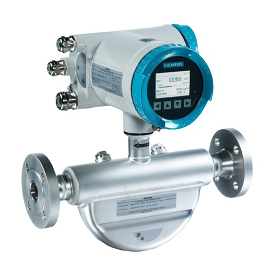
Description SITRANS Coriolis flow meter systems consist of a transmitter and a sensor. The following table lists the available combinations of transmitters and sensors. Transmitter Sensor type FCT030 FCS400 DN 15 to DN 150 (0.5" to 6") The Coriolis flowmeter can be used in a number of system configurations: ●... -
Page 30: Design
The flowmeter uses the Coriolis principle to measure flow and is available in a remote and a compact version. ● Compact version: The SITRANS FC430 is a single mechanical unit where the transmitter is directly mounted on the sensor. ● Remote version: The SITRANS FCS400 sensor unit is remotely connected to a SITRANS FCT030 transmitter. - Page 31 Description 3.1 Design Figure 3-3 Remote version - terminated cable Figure 3-4 Remote version with wallbox Sensor design All primary process measurement of massflow, volumeflow, density and process temperature are made in the DSL/sensor front end. The sensor comprises two parallel bent tubes welded directly to the process connections at each end via a manifold.
-
Page 32: Functions
Description 3.1 Design The sensors are available in AISI 316L stainless steel and Hastelloy C22. The enclosure is made of AISI 304 stainless steel which has a pressure rating of 20 bar (290 psi) for DN 15 to DN 50 and 17 bar (247 psi) for DN 80. The burst pressure for all sizes is in excess of 160 bar. The sensor enclosure can be equipped with a pressure guard or flushed with dry inert gas at the threaded ports for non-hazardous applications only. - Page 33 Description 3.1 Design Transmitter exploded view ① ⑫ Display cover Transmitter housing ② ⑬ Local display (HMI) Terminal space ③ ⑭ Connector for HMI Power supply terminal protection cover ④ ⑮ SD card (SensorFlash) Lid for terminal connections ⑤ ⑯ DIP switch (for custody transfer) Wiring tool ⑥...
-
Page 34: Features
Wall mount housing transmitter exploded view Features ● The flowmeter can be used as HART, Modbus RTU RS485 and PROFIBUS PA/DP slave in operation on SIEMENS SIMATIC S7/PCS 7 or third party automation systems ● Available in compact and remote design FC430 (From firmware 4.0) - Page 35 ● Simulation of outputs ● Simulation of alarms ● Enabling alarms for visibility on all outputs (HMI, status and communication) ● Comprehensive diagnostics (NAMUR or Siemens standard) for troubleshooting and sensor checking ● Firmware update ● Use in hazardous areas according to specification ●...
- Page 36 Description 3.2 Features ● Up to four input/output channels: Channel 1: can be parameterized for: – Profibus DP – Profibus PA – Current Hart output (4-20 mA) – Modbus RTU RS485 Channel 2: Signal output can be parameterized for: – Current output (0/4-20 mA) –...
-
Page 37: Applications
Description 3.3 Applications ● Measurement of: – Volume flow – Mass flow – Standard volume flow – Density – Fraction A (mass flow or volume flow) – Fraction B (mass flow or volume flow) – Fraction A% – Fraction B% –... -
Page 38: Approvals
Description 3.5 Theory of operation ● Oil & Gas: filling of gas bottles, furnace control, test separators, bore-hole plasticizer dosing, water-cut metering ● Water & Waste Water: dosing of chemicals for water treatment Approvals Note For further details see Bus communication (Page 239). The device is available with approvals for general purpose and for hazardous areas. - Page 39 Description 3.5 Theory of operation The frequency and amplitude of the driver is regulated to ensure a stable output from the 2 pickups. The temperature of the sensor tubes is measured to provide accurate compensation for changes in the material stiffness. As a result the process media temperature is also accurately measured.
- Page 40 Description 3.5 Theory of operation FC430 (From firmware 4.0) Operating Instructions, 06/2017, A5E39789392-AA...
-
Page 41: Installing/Mounting
Installing/mounting This chapter gives detailed instructions on mounting the transmitter and sensor to take best advantage of the flexible arrangements built into the product, and to aid in planning the physical locations of the flowmeter parts. With compact types the transmitter can be rotated on the sensor pedestal through 330°. For remote types, as well as 330°... - Page 42 Refer to the information in Technical data (Page 229). Note Material compatibility Siemens can provide you with support concerning selection of sensor components wetted by process media. However, you are responsible for the selection of components. Siemens accepts no liability for faults or failures resulting from incompatible materials.
-
Page 43: Installation Location Requirements
Installing/mounting 4.1 Basic safety notes WARNING Loss of explosion protection Risk of explosion in hazardous areas if the device is open or not properly closed. ● Close the device as described in Installing/mounting (Page 41). CAUTION External stresses and loads Damage to device by severe external stresses and loads (e.g. -
Page 44: Proper Mounting
Installing/mounting 4.1 Basic safety notes WARNING Strong vibrations Risk of explosion in hazardous areas. ● In plants with strong vibrations, mount the transmitter in a low vibration environment. CAUTION Strong vibrations Damage to device ● In plants with strong vibrations, mount the transmitter in a low vibration environment away from the sensor. -
Page 45: Installation Instructions
Installing/mounting 4.2 Installation instructions Installation instructions 4.2.1 Transmitter installation Mounting on wall 1. Prepare holes with aid of mounting bracket, see Mounting bracket (Page 261). 2. Fasten mounting bracket with black cushion pad to wall (torque 10 Nm). Mounting on pipe 1. -
Page 46: Mounting The Transmitter
Installing/mounting 4.2 Installation instructions 4.2.1.1 Mounting the transmitter 1. Remove locking cap from mounting bracket. 2. Mount transmitter on mounting bracket taking care that the flutes on the mating faces are correctly engaged. 3. Firmly tighten locking cap on mounting bracket (torque: 25 Nm). 4.2.1.2 Turning the transmitter Horizontal rotation... -
Page 47: Turning The Transmitter (Remote Version)
Installing/mounting 4.2 Installation instructions 4.2.1.3 Turning the transmitter (remote version) In a configuration with external DSL the transmitter can be turned horizontally and tilted vertically. Horizontal rotation 1. Unscrew cap from lock screw. 2. Loosen lock screw at transmitter pedestal using 5 mm Allen key. 3. -
Page 48: Turning The Local Display
Installing/mounting 4.2 Installation instructions Vertical rotation 1. Loosen locking cap at end of mounting bracket by three turns. 2. Carefully loosen and rotate transmitter into desired position (15° steps). 3. Firmly tighten locking cap (torque: 25 Nm). 4.2.1.4 Turning the local display The local display can be turned in steps of 30°... - Page 49 Installing/mounting 4.2 Installation instructions 6. Carefully push display back into housing. Use a small screwdriver or blade to open the three retaining clips within the transmitter when pushing the display home. 7. Remove O-ring from lid. 8. Reinstall display cover until mechanical stop. Wind back lid by one turn. 9.
-
Page 50: Wall Mount Housing
Installing/mounting 4.2 Installation instructions 4.2.1.5 Wall mount housing Mounting on wall Mounting on wall 1. Prepare holes for the four screws (M6x100 or equivalent). Screw head diameter: max. 13.5 mm; screw shaft diameter: max. 6 mm. 2. Mount transmitter and tighten screws. FC430 (From firmware 4.0) Operating Instructions, 06/2017, A5E39789392-AA... - Page 51 Installing/mounting 4.2 Installation instructions Note Mounting on pipe or in panel For mounting on pipe or in panel, see the installation instructions given in the instruction A5E38640586 which is provided with the optional mounting bracket kit. Mounting on pipe Mounting on pipe 1.
- Page 52 Installing/mounting 4.2 Installation instructions Mounting in front panel Mounting in front panel 1. Cut out a hole in panel as shown. Figure 4-1 Panel cut-out dimensions 2. Remove lid from transmitter housing. 3. From the front of the panel: – Insert housing in cut-out hole. FC430 (From firmware 4.0) Operating Instructions, 06/2017, A5E39789392-AA...
- Page 53 Installing/mounting 4.2 Installation instructions 4. From the back of the panel: – Mount mounting bracket on transmitter housing using four hex socket screws (M6 x 60 or equivalent), four hexagon nuts (M6) with flanges, a 5 mm Allen key, and a 10 mm wrench.
-
Page 54: Sensor Installation
Installing/mounting 4.2 Installation instructions 4.2.2 Sensor installation 4.2.2.1 Determining a location CAUTION Electromagnetic fields Do not install the flowmeter in the vicinity of strong electromagnetic fields, for example near motors, variable frequency drives, transformers etc. Upstream / downstream ● No pipe run requirements, that is straight inlet/outlet sections are not necessary. ●... -
Page 55: Orientation Of The Sensor
Installing/mounting 4.2 Installation instructions Location in the system The optimum location in the system depends on the application: ● Liquid applications Gas or vapor bubbles in the fluid may result in erroneous measurements, particularly in the density measurement. – Do not install the flowmeter at the highest point in the system, where bubbles will be trapped. - Page 56 Installing/mounting 4.2 Installation instructions NOTICE Orienting the sensor To avoid water or moist ingress, transmitters should be oriented with cable entrances aiming downwards. FC430 (From firmware 4.0) Operating Instructions, 06/2017, A5E39789392-AA...
- Page 57 Orienting the sensor The sensor operates in any orientation. The optimal orientation depends on the process fluid and the process conditions. Siemens recommends orienting the sensor in one of the following ways: 1. Vertical installation with an upwards flow (self-draining)
-
Page 58: Installation In A Drop Line
Installing/mounting 4.2 Installation instructions 4.2.2.3 Installation in a drop line Installation in a drop line Installation in a drop line is only recommended if a pipeline reduction or orifice with a smaller cross-section can be installed to create back-pressure and prevent the sensor from being partially drained while measuring. - Page 59 Installing/mounting 4.2 Installation instructions Avoid vibrations ● Make sure that any valves or pumps upstream of the sensor do not cavitate and do not send vibrations into the sensor. ● Decouple vibrating pipeline from the flow sensor using flexible tube or couplings. Figure 4-8 Non-flexible pipes not recommended in vibrating environment Figure 4-9...
-
Page 60: Hydrostatic Testing
Installing/mounting 4.2 Installation instructions 4.2.2.5 Hydrostatic testing The flowmeter is pressure-tested before delivery to 1.5 times the rated working pressure of the sensor. ● In the case of process connections pressure-rated less than 100 bar, the connection is the limiting component. ●... -
Page 61: Disassembly
The selection of pressure guard solution is the responsibility of the user, however Siemens recommends the following forms of pressure guard: ● A pressure switch screwed directly or piped into one of the purge ports and connected to an automatic shut-off valve will disable pressurized supply to the meter. - Page 62 Installing/mounting 4.3 Disassembly WARNING Incorrect disassembly The following risks may result through incorrect disassembly: - Injury through electric shock - Risk through emerging media when connected to the process - Risk of explosion in hazardous area In order to disassemble correctly, observe the following: ●...
-
Page 63: Basic Safety Notes
Connecting Basic safety notes WARNING Energized devices Risk of electric shock or explosion. When energized the device may be opened by qualified personnel only. WARNING Mains supply from building installation overvoltage category 2 A switch or circuit breaker (max. 15 A) must be installed in close proximity to the equipment and within easy reach of the operator. - Page 64 Connecting 5.1 Basic safety notes WARNING Incorrect conduit system Risk of explosion in hazardous areas as result of open cable inlet or incorrect conduit system. ● In the case of a conduit system, mount a spark barrier at a defined distance from the device input.
- Page 65 Connecting 5.1 Basic safety notes WARNING Unsafe extra-low voltage Risk of explosion in hazardous areas due to voltage flashover. ● Connect the device to an extra-low voltage with safe isolation (SELV). WARNING Lack of equipotential bonding Risk of explosion through compensating currents or ignition currents through lack of equipotential bonding.
- Page 66 Connecting 5.1 Basic safety notes WARNING Insufficient isolation of intrinsically safe and non-intrinsically safe circuits Risk of explosion in hazardous areas. ● When connecting intrinsically safe and non‑intrinsically safe circuits ensure that isolation is carried out properly in accordance with local regulations for example IEC 60079-14. ●...
-
Page 67: Connecting Fc430
Connecting 5.2 Connecting FC430 Note Improvement of interference immunity ● Lay signal cables separate from cables with voltages > 60 V. ● Use cables with twisted wires. ● Keep device and cables at a distance from strong electromagnetic fields. ● Take account of the conditions for communication specified in the Technical data (Page 229). -
Page 68: Cable Requirements
– blue cables for installation of intrinsically safe circuits in hazardous areas – gray cables for installation of non-intrinsically safe circuits Further information on Siemens-supplied cables, see Cables and cable entries (Page 236). ● The wire length inside the connection compartment, from the cable gland to the terminals, must be kept as short as possible. - Page 69 Connecting 5.2 Connecting FC430 Take care when handling the cable and passing it through cable ducting that the plug is not subjected to excessive tension (pulling) as the internal connections may be disengaged. Note Never pull the cable by the plug - only by the cable itself. 1.
- Page 70 Connecting 5.2 Connecting FC430 5. Connect wires to terminals according to list below. Terminal number Description Wire color (Siemens) Orange Yellow RS485 / B White RS485 / A Blue 6. Assemble and tighten cable gland 7. Remove O-ring from lid.
- Page 71 Connecting 5.2 Connecting FC430 8. Connect wires to terminals according to list below. Terminal number Description Wire color (Siemens cable) Orange Yellow RS485 / B White RS485 / A Blue 9. Ensure the DIP switches are all set to OFF.
-
Page 72: Preparing For The Transmitter Connections
Connecting 5.2 Connecting FC430 5.2.2.2 Preparing for the transmitter connections WARNING Access to terminal compartment As long as the device is energized, the lid of the housing on the sensor connection area may only be opened by qualified personnel. Before removing the terminal cover, the auxiliary power must be switched off from all poles. Following installation, the terminal cover must be screwed back on again. - Page 73 Connecting 5.2 Connecting FC430 Function Description RL <500 Ohm (HART ≥230 Ohm) Active: Vo=28 V, Io=87mA Current Output - 4 to 20 mA, Passive : Vi=30 V DC, Ii=100 mA Signal Output RL <500 Ohm - C: 0/4 to 20 mA Active: Vo=28 V, Io= 87 mA - F: fmax 10 kHz Passive: Vi=30 V DC, Ii=100 mA...
-
Page 74: Connecting The Current Hart, Ch1
Connecting 5.2 Connecting FC430 The following table shows: ● Which cable with which terminal ● Hardware and software configuration of the channels Figure 5-3 Termination/configuration overview 5.2.2.3 Connecting the Current HART, CH1 Note 4 to 20 mA output It is not required to use shielded cables for the pure 4 to 20 mA current output. Note HART communication It is recommended by the FieldComm Group (FCG) to use shielded cables for the HART... - Page 75 Connecting 5.2 Connecting FC430 5. Connect wires to terminals using wiring tool, field mount transmitter Active current output Passive current output ⑤ ⑥ ④ ⑤ Functional Earth Functional Earth Active current output Passive current output FC430 (From firmware 4.0) Operating Instructions, 06/2017, A5E39789392-AA...
- Page 76 Connecting 5.2 Connecting FC430 6. Connect wires to terminals, wall mount transmitter. Active current output Passive current output 7. Tighten cable gland. Note For Ex versions active or passive current output is preselected at ordering and cannot be changed. Non-Ex versions can be connected as either active or passive. Note Load Signal output: <...
-
Page 77: Connecting The Modbus (Ch1)
Connecting 5.2 Connecting FC430 5.2.2.4 Connecting the Modbus (CH1) 1. Remove cap and ferrule from cable gland and slide onto cable. 2. Push cable through open gland and cable path. 3. Restore ferrule and tighten cap to lightly hold cable in place. 4. -
Page 78: Connecting The Profibus (Ch1)
Connecting 5.2 Connecting FC430 5.2.2.5 Connecting the Profibus (CH1) WARNING Passive channels only Channel 1 power supply must be separated from that for channels 2 to 4. Signal return (or common) can be joined. 1. Remove cap and ferrule from cable gland and slide onto cable. 2. -
Page 79: Connecting Channels 2 To 4
Connecting 5.2 Connecting FC430 6. Connect wires to terminals using wiring tool, wall mount transmitter. PROFIBUS DP/PA ④ In + (B) ⑤ In - (A) ⑥ Out + (B) ⑦ Out - (A) 7. Tighten cable gland. 5.2.2.6 Connecting channels 2 to 4 Channel 2 is for output only and channels 3 to 4 can be connected as either inputs/outputs or relays, see Input/output configuration (Page 81) Connect wires... - Page 80 Connecting 5.2 Connecting FC430 If connected as input or output - Field mount Active configuration Passive configuration ⑫ ⑬ IO[3] (common) IO[3]- (passive) ⑪ ⑫ IO[3]+ (active) IO[3] (common) Functional Earth Functional Earth Table 5-2 If connected as input or output - Wall mount Active configuration Passive configuration ⑫...
-
Page 81: Input/Output Configuration
Connecting 5.2 Connecting FC430 If connected as relay (channels 3 and 4 only) Normally closed contact (NC) Normally open contact (NO) ⑫ ⑬ ⑪ ⑫ Termination example for channel 3 - relay connection 5.2.2.7 Input/output configuration All pressure values are handled as absolute pressure. If connected pressure transmitters measure the pressure in gauge pressure, then please convert to absolute pressure by using the scaling functionality of the flow transmitters current input channel. -
Page 82: Connecting The Power Supply - Field Mount
Connecting 5.2 Connecting FC430 Configura‐ Software configuration Channel tion Input Digital input Active ● Reset totalizer 1 ChX- ● Reset totalizer 2 ChXC ● Reset totalizer 3 ● Reset all totalizers ChX+ ● Force outputs Active ● Freeze process values ●... - Page 83 Connecting 5.2 Connecting FC430 3. Push cable through open gland and cable path. 4. Restore ferrule and tighten cap to lightly hold cable in place. 5. Connect ground to terminal and power to terminals L/+ and N/- using wiring tool in the manner shown below at right.
-
Page 84: Connecting The Power Supply - Wall Mount
Connecting 5.2 Connecting FC430 6. Close and latch power supply terminal protection cover. 7. Tighten cable gland. 5.2.2.9 Connecting the power supply - Wall mount 1. Open enclosure lid, unscrew power supply terminal protection cover screw, and remove protection cover. 2. -
Page 85: Finishing The Transmitter Connection
Connecting 5.2 Connecting FC430 5. Connect ground to terminal and power to terminals L/+ and N/- in the manner shown below at right using a screwdriver. ① ② ③ Protective Earth (PE) AC connection DC connection Power: 100 to 240 V AC, 47 to 63 Hz Power: 19.2 to 28.8 V DC 6. -
Page 86: Wiring Information
Connecting 5.3 Wiring information Your device is now ready for commissioning. Wiring information 5.3.1 Wiring in hazardous areas Hazardous area applications Special requirements apply to the location and interconnection of sensor and transmitter. See Installation in hazardous areas (Page 20). WARNING Transmitter housing Before opening the terminal box check that:... -
Page 87: Device Nameplates
With compact versions, the transmitter and sensor product identifications are both given as 'Coriolis flowmeter SITRANS FC430'. With remote versions, the transmitter is identified as 'Coriolis transmitter SITRANS FCT030' and the sensor as 'Coriolis sensor SITRANS FCS400'. - Page 88 Connecting 5.4 Device nameplates FCT030 transmitter identification nameplate ① Product name Transmitter product name ② System order no. Device-specific system order number (transmitter and sensor) ③ Power Supply Power supply ④ Material Transmitter housing material and style (compact/remote) ⑤ Ambient temp. Ambient temperature ⑥...
- Page 89 The flowmeter serial number is constructed as follows: PPPYMDDxxxxxx where PPP = Production factory (Siemens Flow Instruments: FDK) Y = Production year (for encryption, see below) M = Production month (for encryption, see below) DD = Production date (for encryption, see below)
- Page 90 Connecting 5.4 Device nameplates 1962, 1982, 2002, 2022 1963, 1983, 2003, 2023 1964, 1984, 2004, 2024 1965, 1985, 2005, 2025 1966, 1986, 2006, 2026 1967, 1987, 2007, 2027 1968, 1988, 2008, 2028 1969, 1989, 2009, 2029 Month (M) Code January February March April...
- Page 91 Connecting 5.4 Device nameplates Note Approval identifications Approval certificates and notified body identifications are available for download at www.siemens.com (http://support.automation.siemens.com/WW/view/en/60666565/134200). FCS400 sensor specification nameplate ① Ex approvals Ex approval specifications for the sensor (ATEX example; for details on all approvals refer to Bus communication (Page 239)) ②...
- Page 92 Connecting 5.4 Device nameplates FCT030 transmitter approval nameplate ① QR code Product-specific QR code ② WEEE symbol, see Disposal (Page 189) ③ C✓ C-tick logo ④ FORCE OIML Custody Transfer evaluation certificate number FCS400 sensor approval nameplate ① QR code Product-specific QR code ②...
- Page 93 Connecting 5.4 Device nameplates FCS400 EHEDG nameplate Figure 5-5 EHEDG nameplate This nameplate appears on all Hygienic sensors 7ME462. Other label Figure 5-6 How to install The QR code provides direct internet connection to ● The product support portal, which includes access to the "How to Install" YouTube video. (This example provides that function.) ●...
- Page 94 Connecting 5.4 Device nameplates FC430 (From firmware 4.0) Operating Instructions, 06/2017, A5E39789392-AA...
-
Page 95: Basic Safety Notes
Commissioning In this chapter it is described how to commission the device via the local display using the Quick commissioning wizard. Basic safety notes WARNING Improper commissioning in hazardous areas Device failure or risk of explosion in hazardous areas. ● Do not commission the device until it has been mounted completely and connected in accordance with the information in Installing/mounting (Page 41). - Page 96 Commissioning 6.1 Basic safety notes WARNING Hazardous contact voltage Risk of injury through hazardous contact voltage when the device is open or not completely closed. The degree of protection specified on the nameplate or in Technical data (Page 229) is no longer guaranteed if the device is open or not properly closed.
-
Page 97: Warnings
Commissioning 6.3 Local commissioning 6.1.1 Warnings CAUTION Sensor and transmitter ordered separately If the sensor and the transmitter are ordered separately, a "Set To Default" routine must be performed. This can be done via SIMATIC PDM or via menu item 3.3.3 in HMI. WARNING Dangerous high voltage Certain parts inside the device carry dangerous high voltage. -
Page 98: Initial Startup
Commissioning 6.3 Local commissioning ① Full graphical display ② LED (for indication of key operation) ③ Touch keypad Figure 6-1 Local display Note (Re-)calibration of the keypad When the lid is closed, all keys are (re-)calibrated (< 5 seconds). During (re-)calibration the LED is on and the keys cannot be operated. -
Page 99: Commissioning Via Hmi
Commissioning 6.3 Local commissioning Start Language Welcome Set date and time Quick commissioning Continue with Quick commissioning wizard First startup wizard is now finished Text Options/description Language Set the language: English, Deutsch Welcome Information about the "Quick commissioning" wizard Set date and time The set date and time (real time clock) is used for all time stamps of logged information. - Page 100 Commissioning 6.3 Local commissioning The first time the device is powered up, you will be prompted to set the language. The device always starts up showing Language in English. When the language has been set, you will be prompted to set the date and time. After confirming/changing the date and time you will be asked if you want to start the Quick Commissioning wizard.
-
Page 101: Zero Point Adjustment
Commissioning 6.3 Local commissioning Zero Point Adjustment wizard (menu item 1.2) (Page 103) Inputs/Outputs wizard (menu item 1.4) (Page 107) 6.3.3.3 Zero point adjustment The flowmeter system is optimized through a zero point adjustment which is performed via the Zero Point Adjustment wizard. Performing a zero point adjustment CAUTION Gas application... - Page 102 Commissioning 6.3 Local commissioning 4. During the process a progress bar is visible in the HMI display. 5. At the end of the zero adjustment, the outcome is displayed as an offset and a standard deviation. Note If you get an error message after the zero point adjustment, refer to Zero point adjustment (Page 154).
- Page 103 Commissioning 6.3 Local commissioning 6.3.3.4 Zero Point Adjustment wizard (menu item 1.2) The flowmeter system is optimized through an automatic zero point adjustment. Before you start the zero point adjustment flush the pipe and keep it filled at an absolute flowrate of zero. Ensure that the sensor has the same temperature as the process media.
-
Page 104: Wizards
Commissioning 6.3 Local commissioning Select zero point adjust‐ Auto, Manual ment type Configure Configure duration and limits Auto Adjust Zero point Cancel, Start (progress, result, standard deviation and offset) In progress The progress bar is shown Result Information on success or failure of zero point adjustment View result Standard Deviation and Offset values *: Pressing Cancel will bypass the Zero Point Adjustment and go to view 10. - Page 105 Commissioning 6.3 Local commissioning Use the keys to highlight the desired HMI wizard and press right key to enter the wizard. The first view shows a short description of which settings can be done. Key operation Basic navigation in the HMI wizards is shown in the graphics. To change settings, use the keys to highlight wanted setting, then press key to...
- Page 106 Commissioning 6.3 Local commissioning Process Values wizard (menu item 1.3) The Process Values wizard will guide you through setup of process values for your application. The prioritizing of the process values automatically configures the measurement views on the display. The process value configured as 1st Process Value is set as first display view. View Text Options/Description...
- Page 107 Commissioning 6.3 Local commissioning 4-13 Configure Configure the process values (unit, low flow cut-off, limits, and hys‐ teresis) 14-17 Totalizer Configure totalizers (if activated in operating view, it is possible to reset totalizer without password access) Inputs/Outputs wizard (menu item 1.4) The Input/Output wizard will guide you through setup of inputs and outputs on channels 1 to 4.
- Page 108 Commissioning 6.3 Local commissioning View Text Options/Description Current Output Configure current output basic settings Scaling Configure current mode, upper and lower scaling Fail Safe Mode / Fail Select current output reaction in case of a fault Safe Value *: When pressing you will return to view "Select Channel".
- Page 109 Commissioning 6.3 Local commissioning FC430 (From firmware 4.0) Operating Instructions, 06/2017, A5E39789392-AA...
- Page 110 Commissioning 6.3 Local commissioning Current/Frequency/Pulse View Text Options/Description Operation Mode Select the output functionality Output function Configure the output basic settings Scaling Configure the output scaling 9-10 Fail Safe Mode / Fail Safe Val‐ Select the signal output reaction in case of a fault Status View Text...
- Page 111 Commissioning 6.3 Local commissioning Signal input - channels 3 to 4 The Signal Input can be configured to either Dosing control, Totalizer reset, Remote zero adjust or Force/Freeze output(s). View Text Options/Description Operation Mode Select the signal input functionality Delay Time Set the signal input delay time Polarity Set the signal input polarity...
- Page 112 Commissioning 6.3 Local commissioning Pulsating Flow wizard (menu item 1.6) The Pulsating Flow wizard will guide you through configuration of essential parameters for applications with pulsating flow. As default the Totalizer will be set to Balanced, the Process Noise Damping is set to 4 and the Low Flow Cut-Off value will be raised. View Text Options/Description...
- Page 113 Commissioning 6.3 Local commissioning Dosing Application wizard (menu item 1.7) The Dosing Application wizard will guide you through configuration of each recipe for dosing control including valve control (discrete/analog) and fault handling. The valve control is done using channels 2, 3 and 4. View Text Options/Description...
-
Page 114: Power-Up
For commissioning with SIMATIC PDM, see separate function manual for MODBUS, HART or PROFIBUS. 6.4.1 Operating via SIMATIC PDM SIMATIC PDM is a software package used to commission and maintain process devices. See also www.siemens.com/simatic-pdm (www.siemens.com/simatic-pdm) FC430 (From firmware 4.0) Operating Instructions, 06/2017, A5E39789392-AA... -
Page 115: Operating Instructions
Operating FC430 A considerable amount of information regarding the operation and status of the flowmeter is available to the user via the local display (HMI ) and SIMATIC PDM. In this chapter you will find information on how to monitor and operate the device using the local display (HMI). - Page 116 Operating FC430 7.1 Operating instructions Note Recalibration of the keypad When the lid is mounted, all keys are recalibrated (approximately 40 seconds). During recalibration the LED is on and the keys cannot be operated. If one of the keys is pressed for more than 10 seconds, this key is recalibrated (duration less than 10 seconds).
-
Page 117: Display View Structure
Operating FC430 7.1 Operating instructions 7.1.1.1 Display view structure There are three view types: ● Operation view The operator view shows up to six operation views (Page 122). The operation views are fully configurable to show different process values in different operation view types. Depending on the operation view type configuration the view is either measurement view or alarm view. - Page 118 Operating FC430 7.1 Operating instructions Table 7-3 Alarm view level 2 Function Enter alarm view level 1 Select the item above in the list; keep pressing the key to accelerate scrolling up the selection list Select the item below in the list; keep pressing the key to accelerate scrolling down the selection list Enter alarm view level 3 Table 7-4...
- Page 119 Operating FC430 7.1 Operating instructions Function Go to the next menu in the operation view Enter the navigation view The following graphic shows an example of how to navigate between measurement views and alarm views with measurement views 1, 3, and 4 as well as alarm view 5 enabled. ①...
- Page 120 Operating FC430 7.1 Operating instructions Navigating the navigation view Browse the navigation view and menu items using the control buttons as follows: Table 7-8 Navigation view Function Enter the next higher level of the navigation view (for example from level 2 to level 1). If located on level 1 in the navigation view then enter the operation view.
-
Page 121: Access Control
The exact structure of the operating menu is explained in the HMI menu structure (Page 277). Note Lost PIN code If the PIN code is lost, provide Siemens customer support with the transmitter serial number (see nameplate). Siemens customer support will provide a code to be entered in Reset PINs (menu item 5.1.3). -
Page 122: Operation View
Operating FC430 7.1 Operating instructions Auto Log Off function With the "Auto Log Off" function enabled (default), you will be prompted to enter the password if no keys have been pressed for ten minutes before operating the display again. With the "Auto Log Off"... -
Page 123: Measurement Views
Operating FC430 7.1 Operating instructions ① Long TAG Describes the measurement point and is shown in all operation views. Can be changed via the menu "Long TAG" (3.1.1). ② View number Shows the operation view number. The number refers to the view num‐ ber configured in the menu "Setup"... - Page 124 Operating FC430 7.1 Operating instructions Three values ① First process value The user-defined process value to be displayed is configured in menu "View" (1-6) located at "Setup" → "Display" ② Lower Limit Alarm The lower limit of the bar graph is defined by the lower alarm limit of the selected process value.
- Page 125 Operating FC430 7.1 Operating instructions Note Bargraph The bargraph limits are defined as the lower and upper alarm values. One value and graph ① Process Value ② Graph ③ Instruction Press to freeze/unfreeze display Six values ① First process value The user-defined process value to be displayed is configured in menu "View"...
-
Page 126: Operating Views
Operating FC430 7.1 Operating instructions 7.1.1.5 Operating views Operating Views Totalizer (level 1) ① Process value ② Graph ③ Instruction Press to enter the operation view. Totalizer (level 2) ① Process value ② Graph ③ Control Dosing (level 1) ① Dosed amount Actual dosed amount ②... -
Page 127: Alarm Views
Operating FC430 7.1 Operating instructions Dosing (level 2) ① Dosed amount Actual dosed amount ② Amount Dosing progress ③ Count Number of dosings ④ Recipe Name of the selected recipe ⑤ Status Dosing status ⑥ Control Dosing control 7.1.1.6 Alarm views Alarm views Alarm List (level 1) ①... - Page 128 Operating FC430 7.1 Operating instructions Alarm List (level 2) ① List of alarms List of all active alarms in device. Each Alarm can be selected for detailed information. ② Alarm icon Shows the alarm class, see Device status symbols (Page 199). ③...
-
Page 129: Diagnostic Views
Operating FC430 7.1 Operating instructions Alarm acknowledgement There are two ways to have the alarms removed from the alarm list. ● Manual: The alarm remains in the alarm list until the alarm is manually acknowledged (ack.). The time of the acknowledgement is shown in the history log. ●... - Page 130 Operating FC430 7.1 Operating instructions Level 1 of the navigation view (entered from the operation view) is standardized for all Siemens Process Instrumentation devices and covers the following groups: 1. Quick Start (menu): Lists the most important parameters for quick configuration of the device.
-
Page 131: Parameter View
Operating FC430 7.1 Operating instructions Parameter item In navigation view parameters are shown without an arrow in the most right position except when the parameter is selected. When selected, the parameter is expanded into two lines; the second line shows the value of the parameter, a lock icon ( ) (only for read access level of the parameter), and an arrow in most right position. - Page 132 Operating FC430 7.1 Operating instructions Numeric parameters edit view Numeric parameters in edit view are displayed as shown here. ① Parameter name ② Parameter item number ③ Maximum value ④ Escape without saving (frame around ESC is only shown when cursor is in left-most position) ⑤...
- Page 133 Operating FC430 7.1 Operating instructions In order to change the resolution of the process value shown in the operation view (for example massflow), change the resolution of one configuration parameter for this process value (for example "Low Flow Cut-off" (menu item 2.2.1.2)). Any changes in resolution will change the resolution of all configuration parameters for this process value as well.
- Page 134 Operating FC430 7.1 Operating instructions Parameter list edit view Lists of parameters in edit view are displayed as shown here. ① Parameter list ② Parameter name ③ Parameter item number ④ Help text describing the parameter function. The help text appears if no key is pressed for three seconds.
- Page 135 Operating FC430 7.1 Operating instructions Multiselection view It is possible to select/deselect multiple alarms to be suppressed. ① Parameter name ② Alarm list ③ Save settings (select and press right key to save settings) to scroll through the alarms. Use to select/deselect the alarm.
- Page 136 Operating FC430 7.2 HMI The following graphic shows an example of how to navigate between measurement views and alarm views with measurement views 1, 3, and 4 as well as alarm view 5 enabled. ① Measurement view ② Access level view ③...
- Page 137 Operating FC430 7.2 HMI In general, all of the HMI views show the following: ① Long TAG Describes the measurement point and is shown in all operation views. Can be changed via the menu "Long TAG" (3.1.1). ② View number Shows the operation view number.
- Page 138 Operating FC430 7.2 HMI Three Values ① First process value The user-defined process value to be displayed is configured in menu "View" (1-6) located at "Setup" → "Display" ② Lower Limit Alarm The lower limit of the bar graph is defined by the lower alarm limit of the selected process value.
- Page 139 Operating FC430 7.2 HMI Note Bargraph The bargraph limits are defined as the lower and upper alarm values. 1 Value and Graph ① Process Value ② Graph ③ Instruction Press to freeze/unfreeze display Six Values ① First process value The user-defined process value to be displayed is configured in menu "View"...
- Page 140 Operating FC430 7.2 HMI Operating Views Totalizer (level 1) ① Process value ② Graph ③ Instruction Press to enter the operation view. Totalizer (level 2) ① Process value ② Graph ③ Control Dosing (level 1) ① Dosed amount Actual dosed amount ②...
- Page 141 Operating FC430 7.2 HMI Dosing (level 2) ① Dosed amount Actual dosed amount ② Amount Dosing progress ③ Count Number of dosings ④ Recipe Name of the selected recipe ⑤ Status Dosing status ⑥ Control Dosing control Alarm views Alarm List (level 1) ①...
- Page 142 Operating FC430 7.2 HMI Alarm List (level 2) ① List of alarms List of all active alarms in device. Each Alarm can be selected for detailed information. ② Alarm icon Shows the alarm class, see Sensor diagnostic events (Page 203). ③...
- Page 143 Operating FC430 7.2 HMI Alarm acknowledgement There are two ways to have the alarms removed from the alarm list. ● Manual: The alarm remains in the alarm list until the alarm is manually acknowledged (ack.). The time of the acknowledgement is shown in the history log. ●...
- Page 144 Operating FC430 7.2 HMI Fixed display text Process value name FRACTION B Fraction B FRCT.A % Fraction A % FRCT.B % Fraction B % TOT1 Totalizer 1 TOT2 Totalizer 2 TOT3 Totalizer 3 Table 7-12 Diagnostic values Fixed display text Diagnostic value name DRIV.CURR.
- Page 145 Operating FC430 7.2 HMI Parameter item In navigation view parameters are shown without an arrow in the most right position except when the parameter is selected. When selected, the parameter is expanded into two lines; the second line shows the value of the parameter, a lock icon ( ) (only for read access level of the parameter), and an arrow in most right position.
- Page 146 Operating FC430 7.2 HMI Numeric parameters edit view Numeric parameters in edit view are displayed as shown here. ① Parameter name ② Parameter item number ③ Maximum value ④ Escape without saving (frame around ESC is only shown when cursor is in left-most position) ⑤...
- Page 147 Operating FC430 7.2 HMI In order to change the resolution of the process value shown in the operation view (for example massflow), change the resolution of one configuration parameter for this process value (for example "Low Flow Cut-off" (menu item 2.2.1.2)). Any changes in resolution will change the resolution of all configuration parameters for this process value as well.
- Page 148 Operating FC430 7.2 HMI Parameter list edit view Lists of parameters in edit view are displayed as shown here. ① Parameter list ② Parameter name ③ Parameter item number ④ Help text describing the parameter function. The help text appears if no key is pressed for three seconds.
- Page 149 Operating FC430 7.2 HMI Multiselection view It is possible to select/deselect multiple alarms to be suppressed. ① Parameter name ② Alarm list ③ Save settings (select and press right key to save settings) to scroll through the alarms. Use to select/deselect the alarm. The marked alarms will NOT be suppressed.
- Page 150 Operating FC430 7.2 HMI FC430 (From firmware 4.0) Operating Instructions, 06/2017, A5E39789392-AA...
-
Page 151: Process Values
Functions Process values The process values are updated every 10 ms (100 Hz update rate) synchronous with the DSP update cycle. Process value parameters The process values are: ● Mass flow ● Volume flow ● Standard volume flow ● Density ●... - Page 152 Functions 8.1 Process values value exceeds the Upper Limit Warning or the Lower Limit Warning. Process value alarms and warnings are displayed in the HMI as well as at the communication interfaces. Hysteresis The hysteresis functions as follows: Figure 8-1 Hysteresis A: Upper Alarm Limit with hysteresis The alarm is triggered when the process value overshoots the Upper Alarm Limit (1).
- Page 153 Functions 8.1 Process values Hysteresis is used to adjust the tolerance by undershooting or overshooting the limit as described below. Process value derivations The front-end of the device measures time and derives the values of certain process variables from those measurements. The time period of vibration of the two measuring tubes is inversely proportional to their frequency, which is used to determine density.
-
Page 154: Zero Point Adjustment
Functions 8.2 Zero point adjustment Zero point adjustment In the following the automatic zero point adjustment function is described. For further details, see the appendix Zero point adjustment. Note Preconditions Before a zero point adjustment is initiated, the pipe must be flushed, filled and at an absolute flowrate of zero preferably also at operating pressure and temperature. -
Page 155: Low Flow Cut-Off
Functions 8.4 Empty tube monitoring Manual zero point adjustment In case an automatic zero point adjustment cannot be performed, it is possible to do a manual zero point adjustment by entering the zero point offset value. 1. Select "Manual" in "Select Zero Point Adj." (menu item 2.6.1). 2. -
Page 156: Process Noise Damping
Functions 8.5 Process noise damping The tube is defined as empty, if the measured density value is lower than the value defined via the Empty Tube Limit parameter. Note Process media density Risk of unintentionally forcing flow values to zero, if the difference between the empty tube limit density value and the density of the process media is not sufficient. - Page 157 Functions 8.5 Process noise damping Figure 8-2 Centrifugal pump (1: low) Figure 8-3 Triplex pump (2) Figure 8-4 Duplex pump (3; default setting) Figure 8-5 Simplex pump (4) FC430 (From firmware 4.0) Operating Instructions, 06/2017, A5E39789392-AA...
-
Page 158: Inputs And Outputs
Functions 8.6 Inputs and outputs Figure 8-6 Cam pump (5: high) Note Increased reaction time The reaction time of the sensor increases when the process noise is damped. Inputs and outputs The hardware functionality of input and output is fixed when ordering the product. The available configuration is described in the following table: Channel HW configuration... -
Page 159: Current Output
Functions 8.6 Inputs and outputs Channel HW configuration SW configuration (fixed when ordering) available to the user Signal output ● Current (0/4-20 mA) ● Frequency or pulse ● Redundant frequency or pulse (together with channel ● Three-stage analog valve dosing control ●... - Page 160 Functions 8.6 Inputs and outputs ● Fraction B (Volume flow or Mass flow) ● Fraction A % ● Fraction B % ● Control valve * The process variable listed above with * is not available to be allocated to the 4 to 20 mA output on Channel 1.
- Page 161 Functions 8.6 Inputs and outputs ● Current Value (actual measured value) ● User defined (within the range of 0 mA to 25 mA For channel 1 the range is 3.5 mA to 25 mA In the alarms lists inSensor diagnostic events (Page 203) it is listed which alarms bring the output to fail safe current.
- Page 162 Functions 8.6 Inputs and outputs ● Fail Safe Mode = Maximum current ● Low-Flow Cut-Off = 25 kg/h Positive flow across zero with positive scaling Kg/h 400 kg/h -100 kg/h ① Lower scaling ② Low-flow cut-off ③ Upper scaling ④ Maximum measurement value ⑤...
- Page 163 Functions 8.6 Inputs and outputs Bidirectional flow across zero with positive scaling Kg/h ① Lower scaling ② Low-flow cut-off ③ Upper scaling ④ Maximum measurement value ⑤ Upper range ⑥ Lower range ⑦ Minimum measurement value ⑧ Lower alarm value ⑨...
-
Page 164: Pulse Output
Functions 8.6 Inputs and outputs Bidirectional flow with symmetrical scaling Kg/h ① Upper scaling ② Lower scaling ③ Low-flow cut-off ④ Upper alarm value ⑤ Maximum measurement value ⑥ Upper range ⑦ Lower range ⑧ Minimum measurement value ⑨ Measurement range Current output setting ●... -
Page 165: Frequency Output
Functions 8.6 Inputs and outputs Pulse repetition Pulse repetition is calculated as follows: Note Pulse width must be selected with the view that remaining time is always greater than pulse width at the highest measured flow. Example ● Pulse output configuration (channels 2 to 4) –... -
Page 166: Redundancy Mode (Frequency)
Functions 8.6 Inputs and outputs ● Direction = Positive ● Frequency Value High = 12 kHz ● Frequency Value Low = 2 kHz ● Flow Value High = 15 kg/s ● Flow Value Low = 5 kg/s Measured massflow value = 7.5 kg/s (constant) Result: ●... - Page 167 Functions 8.6 Inputs and outputs Channel 2 configured as positive direction and channel 3 set to redundancy mode 180˚ Figure 8-10 Positive flow - channel 3 leads by 180° Figure 8-11 Negative flow - channel 3 lags by 180° Redundancy mode (pulse) If both channel 2 and channel 3 are configured as pulse outputs, channel 3 can be configured for redundancy mode to follow channel 2 shifted by 90˚or 180˚...
-
Page 168: Digital Output
Alarm class The alarm class options depend on the Alarm Mode setting, either NAMUR or Standard (Siemens Standard), selected in menu item 3.2.1. Both NAMUR and Siemens Standard alarms and their messages are described in more detail in Sensor diagnostic events (Page 203). -
Page 169: Totalizers
Functions 8.7 Totalizers The following input options are available: ● Start dosing ● Hold / continue dosing – When this function is activated, it will pause the dosing. When it is deactivated, the dosing will continue ● Stop dosing – Sets the digital output to "Off" and resets the dosing counter ●... -
Page 170: Dosing
Functions 8.8 Dosing - Memory: the totalizer continues counting based on the last input value (for example massflow) before the failure occurred. The totalizers can be operated via the Local User Interface or bus communication (for example SIMATIC PDM). The totalizers can be reset or preset. Dosing The dosing function controls the sequence of flow through one or two valves into a container. -
Page 171: Dosing Control Configuration
Functions 8.8 Dosing Configure the dosing function as follows: 1. Basic dosing parameters common for all recipes in menu 2.5 "Dosing" – Select valve control functionality at parameter "Dosing Mode" – Select measured process value for dosing at parameter "Process Values" 2. -
Page 172: Valve Control Configuration
Functions 8.8 Dosing ● Standard volume flow ● Fraction A ● Fraction B Recipes Five recipes can be configured individually, however only one of the recipes can be active at a time. 8.8.2 Valve control configuration Valve control dosing Dosing is controlled with either one or two discrete valves or a single analog valve. The transmitter provides up to three input/output channels which can be used for dosing control. - Page 173 Functions 8.8 Dosing One of the following channels must be assigned to control the discrete primary valve and one must be assigned to control the secondary discrete valve. Table 8-2 Two on/off valves Valve control Channel HW con‐ Output Channel SW configuration figuration channel Menu item...
- Page 174 Functions 8.8 Dosing Table 8-4 Parameter settings for Two on/off valves valve control Valve control parameter config‐ Default values Description ured in each recipe Stage 1 Primary Open 0.00 % of Amount The quantity or percent of the Amount at which the primary valve will open Stage 1 Primary Close 80.00 % of Amount...
- Page 175 Functions 8.8 Dosing ① Open primary valve ② Open secondary valve ③ Close primary valve ④ Close secondary valve Example 2: Open primary valve at 0 %; close primary valve after closing secondary valve configured in recipe 1 Parameter configuration: Menu 2.5 Dosing - 2.5.1 Dosing Mode = Two on/off valves Menu 2.5.5.6 Valve Control...
- Page 176 Functions 8.8 Dosing ① Open secondary valve ② Open primary valve ③ Close primary valve ④ Close secondary valve Example 4: Open secondary valve at 0 %; close primary valve after closing secondary valve configured in recipe 1 Parameter configuration: Menu 2.5 Dosing - 2.5.1 Dosing Mode = Two on/off valves Menu 2.5.5.6 Valve Control...
-
Page 177: Dosing Operation
Functions 8.8 Dosing Three-positional Control valve configured in recipe 1 Parameter configuration: Menu 2.5 Dosing 2.5.1 Dosing Mode = Control valve Menu 2.5.4.5 Valve Control 2.5.4.5.1 Stage Setup Format = Relative 2.5.4.5.6 Fully Closed Current Level = 0 mA 2.5.4.5.7 Partial Open Current Level = 10 mA 2.5.4.5.8 Fully Open Current Level = 20 mA 2.5.4.5.9 Fully Open = 35 % 2.5.4.5.10 Partially Closed = 65 %... -
Page 178: Fault Handling
Functions 8.10 Diagnostic log 8.8.4 Fault handling The transmitter fault handling provides monitoring of both dosing time and amount. The configuration of the fault handling is done in menu 2.5.4.6 Fault Handling. Dosing timeout monitoring The dosing timeout monitoring checks whether the dosing procedure has been finished within the configured Duration Time (menu item 2.5.5.7.2 for Recipe 1). -
Page 179: Custom Unit
Further is contains parameter backup files, firmware logs, alarm history log, parameter change log and data logging of process values and parameters. The Siemens SensorFlash memory unit offers a permanent database with backup of all parameter settings. The SensorFlash supports copy and transfer of user settings from one flowmeter to another to simplify commissioning. -
Page 180: Datalogging On Sensorflash
Functions 8.15 Simulation 5. Please wait… 6. Copy/restore parameterization - succeeded. Press right key to continue… Copy/restore parameterization - failed. Press right key to continue… 8.13 Datalogging on sensorFlash Datalogging of process values can be activated under menu items 3.7 - SensorFlash Data logging can be selected in different logging intervals for Process values and for advanced logging of parameters. -
Page 181: Maintenance
Alarm simulation It is possible to simulate either specific alarms (ID numbers) or alarm classes. The alarm classes are either Siemens or NAMUR depending on the configuration of Alarm Mode, menu item 2.8.11. Any simulated alarms will be time-stamped 1900-01-01 00:00 if the alarms have not previously appeared as real alarms. - Page 182 Functions 8.16 Maintenance FC430 (From firmware 4.0) Operating Instructions, 06/2017, A5E39789392-AA...
-
Page 183: Basic Safety Notes
● Reliability of power supply, lightning protection, and grounds WARNING Impermissible repair and maintenance of the device ● Repair and maintenance must be carried out by Siemens authorized personnel only. WARNING Dust layers above 5 mm Risk of explosion in hazardous areas. -
Page 184: Recalibration
● Ensure that the atmosphere is explosion-free (hot work permit). Recalibration Siemens A/S, Flow Instruments offers to recalibrate the sensor at our works in Denmark. The following calibration types are offered as standard according to configuration (standard, density, °Brix/°Plato, fraction): ●... -
Page 185: Cleaning
WARNING Impermissible repair of explosion protected devices Risk of explosion in hazardous areas ● Repair must be carried out by Siemens authorized personnel only. WARNING Maintenance during continued operation in a hazardous area There is a risk of explosion when carrying out repairs and maintenance on the device in a hazardous area. - Page 186 Service and maintenance 9.4 Maintenance and repair work WARNING Humid environment Risk of electric shock. ● Avoid working on the device when it is energized. ● If working on an energized device is necessary, ensure that the environment is dry. ●...
- Page 187 ● Seal integrity of the process connections, cable entries, and cover screws ● Reliability of power supply, lightning protection, and grounds NOTICE Repair and service must be carried out by Siemens authorized personnel only. Note Siemens defines flow sensors as non-repairable products.
-
Page 188: Service Information
Service and maintenance 9.5 Replacing the device ● HMI Hardware Revision ● Sensor Hardware Revision 9.4.1 Service information Service information is information about the condition of the device used for diagnostics and service purposes. Service information parameters The basic service information parameters are: ●... -
Page 189: Return Procedure
– Number of returned devices/replacement parts – Reason for returning the item(s) ● Decontamination declaration (http://www.siemens.com/sc/declarationofdecontamination) With this declaration you warrant "that the device/replacement part has been carefully cleaned and is free of residues. The device/replacement part does not pose a hazard for humans and the environment."... -
Page 190: Spare Parts/Accessories
9.8 Spare parts/Accessories Spare parts/Accessories 9.8.1 Ordering of spare parts Ensure that your ordering data is not outdated. The latest ordering data is always available on the Internet: Catalog process instrumentation (http://www.siemens.com/ processinstrumentation/catalogs) 9.8.2 Ex approved products WARNING Repair of Ex-approved products It is the customer's responsibility that repair of Ex-approved products fulfill national requirements. - Page 191 Service and maintenance 9.8 Spare parts/Accessories Component Order number Photo and Hot swappable position on Design (Page 30) ① SITRANS FCT030 A5E03549344 Display lid Observe hazard‐ Display lid in painted aluminum A5E38510378 ous area access protocols! with window SITRANS FCT030 A5E03549396 Bag of loose spare parts ⑮...
- Page 192 Service and maintenance 9.8 Spare parts/Accessories Component Order number Photo and Hot swappable position on Design (Page 30) SITRANS FCS400 A5E03549324 Contents: Bag of loose parts for sensor Screws, O-rings, cable clamp parts SITRANS FCT030 A5E03906091 Remote version Mounting bracket kit for wall and pipe mounting SITRANS FCS400 A5E03906095...
- Page 193 Service and maintenance 9.8 Spare parts/Accessories Component Order number Photo and Hot swappable position on Design (Page 30) Transmitter Cassette for firmware A5E38012278 Ch1: I/O and comm (active) 4….20 mA output and HART 7.5 Transmitter Cassette for firmware A5E38013025 Ch1: I/O and comm (passive) 4….20 mA output and HART 7.5 Non-Ex Transmitter Cassette for firmware...
- Page 194 Service and maintenance 9.8 Spare parts/Accessories Component Order number Photo and Hot swappable position on Design (Page 30) Ch3: Curent/Frequency/Pulse Ch4: Relay Non-Ex I/O Cassette for firmware 4.0 A5E38006900 Ch2: Curent/Frequency/Pulse Ch3: Relay Ch4: Relay Non-Ex I/O Cassette for firmware 4.0 A5E38011432 Ch2: Curent/Frequency/Pulse Ch3: Relay...
- Page 195 Component Order number Photo Hot swappable Display and keypad assembly A5E37697615 For wall mount enclosure, With Siemens logo Display and keypad assembly A5E39844261 For wall mount enclosure, Neutral version Power supply for wall mount A5E38263021 100 - 240 V AC, 47 - 63 Hz, 19,2 - 28,8 V DC FC430 (From firmware 4.0)
- Page 196 Foam insert set for wall mount with A5E38287828 connectors Wall mount enclosure front, blind, A5E38287882 Siemens version Wall mount enclosure front, blind, A5E38287965 Neutral version - no company logo Wall mount enclosure front w. glass A5E38288007 Wall mount enclosure bracket for...
-
Page 197: Field Enclosure Spareparts
Display and keypad assembly for A5E37705139 field mount enclosure With adapter cable to the transmit‐ ter module With Siemens logo (for all HW and FW versions) Display and keypad assembly for A5E39844362 field mount enclosure With adapter cable to the transmit‐... - Page 198 Service and maintenance 9.8 Spare parts/Accessories Component Order number Photo Hot swappable Wall bracket for FCT010 A5E42404447 For M20 analog cable connection Sensor cassette (Compact). A5E41526318 For systems without DSL (HW version 3, FW 4.0) Sensor cassette (Remote). For systems with DSL (HW version 3, FW 4.0) 1.
-
Page 199: Device Status Symbols
Diagnostic log. The alarm history log can be reset in Reset log. Characteristics of messages The device provides two types of alarm formats, Siemens standard alarm classes and NAMUR status signals, selected in Status icons. - Page 200 Diagnosing and troubleshooting 10.1 Device status symbols NAMUR status signals Icon Priority Name Description level Failure ● Failure ● Invalid output signal Out of specification ● Out of specification ● Device will still work, but output signals may be invalid Maintenance required ●...
- Page 201 Diagnosing and troubleshooting 10.1 Device status symbols Symbols Table 10-1 Mapping of device states in SIMATIC products (e.g. SIMATIC PDM) and NE107 SIMATIC PDM / PLC NAMUR NE 107 Description Measure Icon Device Pri‐ Icon Device Pri‐ status ority status ority Mainte‐...
-
Page 202: Fault Codes And Corrective Actions
10.2 Fault codes and corrective actions Alarms and system messages support both Siemens standard alarm classes and NAMUR status signals. In the following tables the alarm IDs (identification numbers) are listed along with possible causes and directions for corrective action. -
Page 203: Sensor Diagnostic Events
The device can be put into Safe Operation mode after validation Sensor supply volt. out of range Contact your local Siemens representative Sensor supply volt. out of range Contact your local Siemens representative Temperature measurement fault Turn off the power, wait 5 seconds and turn on the power again. - Page 204 Siemens representative Invalid calibration data Contact your local Siemens representative for recalibration Invalid compensation data Contact your local Siemens representative Malfunction in Pickup Amplitude Contact your local Siemens representative FC430 (From firmware 4.0) Operating Instructions, 06/2017, A5E39789392-AA...
- Page 205 10.2 Fault codes and corrective actions Diagnostic Action Comments Icons Malfunction in Pickup Amplitude Contact your local Siemens representative Malfunction in Pickup Amplitude Contact your local Siemens representative Malfunction in sensor driver Contact your local Siemens representative Malfunction in sensor driver...
- Page 206 Comments Icons Fluid temp. below limit Increase the fluid temperature. If the failure con‐ tinues then contact your local Siemens repre‐ sentative Fluid temp. above limit Reduce the fluid temperature. If the failure con‐ tinues then contact your local Siemens repre‐...
- Page 207 Icons Parameter storage malfunction Turn off the power, wait 5 seconds and turn on the power again. If the failure continues then contact your local Siemens representative Internal error in sensor Contact your local Siemens representative Internal error in sensor...
-
Page 208: Transmitter Diagnostic Events
Check sensor cable connection. Wait 20 sec‐ onds. If the status remains 'Coming' then turn off the power, wait 5 seconds and turn on the power again. If the failure continues then con‐ tact your local Siemens representative 10.2.2 Transmitter diagnostic events Transmitter diagnostic events... - Page 209 Diagnosing and troubleshooting 10.2 Fault codes and corrective actions Diagnostic Action Comment Icons Volume flow Value above warning limit. Check process con‐ ditions or align limit to normal operation. Adjust parameter 'Upper warning limit' Volume flow Value below warning limit. Check process con‐ ditions or align limit to normal operation.
- Page 210 Diagnosing and troubleshooting 10.2 Fault codes and corrective actions Diagnostic Action Comment Icons Medium temperature Value below warning limit. Check process con‐ ditions or align limit to normal operation. Adjust parameter 'Lower warning limit' Medium temperature Value below alarm limit. Check process condi‐ tions or align limit to normal operation.
- Page 211 Diagnosing and troubleshooting 10.2 Fault codes and corrective actions Diagnostic Action Comment Icons Fraction B % Value below alarm limit. Check process condi‐ tions. Align Lower alarm limit to normal process conditions. Fraction A flow Value above alarm limit. Check process condi‐ tions.
- Page 212 Diagnosing and troubleshooting 10.2 Fault codes and corrective actions Diagnostic Action Comment Icons Standard density Value above alarm limit. Check process condi‐ tions. Align Upper alarm limit to normal process conditions. Standard density Value above warning limit. Check process con‐ ditions.
- Page 213 Diagnosing and troubleshooting 10.2 Fault codes and corrective actions Diagnostic Action Comment Icons Totalizer 1 Value above warning limit. Check process con‐ ditions or align limit to normal operation. Adjust parameter 'Upper warning limit' Totalizer 1 Value below warning limit. Check process con‐ ditions or align limit to normal operation.
- Page 214 Sensor signal disrupted Turn off the power. Unplug and reconnect the sensor cable. Restore power. If the error still exists, contact your local Siemens representa‐ tive. SensorFlash Backup disabled. Another SensorFlash was in‐ serted. To acknowlege please copy the config‐...
- Page 215 Functional safety Device detected an event in safe operation. Ac‐ knowledge the safety event in menu Functional Safety and repeat the safety commissioning. If the error still exists, contact your local Siemens representative. Cable break. Check current output cable con‐ nection Internal error Internal error in transmitter.
- Page 216 Diagnosing and troubleshooting 10.2 Fault codes and corrective actions Diagnostic Action Comment Icons Standard volume flow Value simulated. Disable 'Simulation' before re‐ Only hydrocarbon turning to normal operation Totalizer 1 Value simulated. Disable 'Simulation' before re‐ turning to normal operation Totalizer 2 Value simulated.
- Page 217 Diagnosing and troubleshooting 10.2 Fault codes and corrective actions Diagnostic Action Comment Icons Sensor Sensor type incompatible. Please replace sen‐ sor. Device is starting Please wait until startup is finished. Startup time see manual. Transmitter FW invalid. A component does not have the ex‐ pected FW version.
- Page 218 Dosing quantity overrun. Check installation. If ok, decrease 'Overrun Value' Dosing Invalid process value during dosing. Check in‐ stallation for abnormal operating conditions. If the error still exists, contact your local Siemens representative. FC430 (From firmware 4.0) Operating Instructions, 06/2017, A5E39789392-AA...
- Page 219 Diagnosing and troubleshooting 10.2 Fault codes and corrective actions Diagnostic Action Comment Icons Loop current in lower saturation. Check process If Operation mode is config‐ conditions or align limit to normal operation. Ad‐ ured to Current output just channel 2 parameter 'Lower range value' Loop current in upper saturation.
- Page 220 Diagnosing and troubleshooting 10.2 Fault codes and corrective actions Diagnostic Action Comment Icons Frequency too low. Check process conditions If Operation mode is config‐ or align limit to normal operation. Adjust chan‐ ured to Frequency output nel 3 parameter 'Lower range value' Frequency too high.
- Page 221 Diagnosing and troubleshooting 10.2 Fault codes and corrective actions Diagnostic Action Comment Icons Channel simulated. Disable 'Simulation' before returning to normal operation Channel simulated. Disable 'Simulation' before returning to normal operation Channel simulated. Disable 'Simulation' before returning to normal operation Process values frozen All process values and totalizers are frozen.
-
Page 222: Operation Troubleshooting
Diagnosing and troubleshooting 10.3 Operation troubleshooting Diagnostic Action Comment Icons Modbus Invalid coil configuration. Modbus coils are not configured correctly. Check coil allocation. Datalogging DATALOGGING 30 DAYS LEFT Datalogging DATALOGGING 7 DAYS LEFT Datalogging DATALOGGING SDCARD FULL Frame temperature simulated Value simulated. -
Page 223: Troubleshooting Sensor-Related Problems
Diagnosing and troubleshooting 10.3 Operation troubleshooting 10.3.2 Troubleshooting sensor-related problems Incorrect and unstable measurements, especially at low flows, are typically a result of an unstable zero point due to: ● Incorrect installation ● Bubbles in the liquid ● Vibrations/Cross talk ●... - Page 224 Diagnosing and troubleshooting 10.3 Operation troubleshooting Step 2: Performing a zero point adjustment The second step in the troubleshooting procedure is to zero point adjust the device. For further information on zero point adjustment, see Commissioning (Page 95). Step 3: Calculating the measurement error The result of the zero point adjustment will show you if the zero point was set under good and stable conditions.
- Page 225 Diagnosing and troubleshooting 10.3 Operation troubleshooting Supply voltage Un ± 1 % Warming-up time 30 min. Cable length 5 m between transmitter and sensor Table 10-3 Additions in the event of deviations from reference conditions Current output As pulse output ± (0.1% of actual flow +0.05 % FSO) Effect of ambient ●...
- Page 226 Diagnosing and troubleshooting 10.3 Operation troubleshooting Vibrations / cross talk have a greater or lesser effect upon the zero point stability and therefore also the measurement accuracy. 1. Check whether there are vibrations. Turn off the pump and check whether the zero point stability improves, that is if the flowrate fluctuation in kg/h is reduced.
-
Page 227: How Do I Update The Firmware
10.3.3 How do I update the firmware? 1. Download the new firmware bundle from (www.siemens.com/FC430) and save it to the SensorFlash. An instruction is also available at this site. 2. Access the flowmeter with access level Expert (the default PIN code is 2834). - Page 228 Diagnosing and troubleshooting 10.4 Diagnosing with PDM FC430 (From firmware 4.0) Operating Instructions, 06/2017, A5E39789392-AA...
-
Page 229: Power
Technical data Note Device specifications Siemens makes every attempt to ensure the accuracy of these specifications but reserves the right to change them at any time. 11.1 Power Table 11-1 Power supply Description Specification Supply voltage ● 100 to 240 V AC, 47 to 63 Hz 30 VA ●... - Page 230 Technical data 11.2 Performance Table 11-3 Massflow accuracy Description Specification Sensor size DN15 DN25 DN50 DN80 DN100 DN150 Qmin - minimum flowrate [kg/h] (lb/min) 4160 6880 (0.735) (7.35) (27.6) (33.1) (153) (253) Qnom - nominal flowrate [kg/h] (lb/min) 3700 11500 52000 136000 285800...
-
Page 231: Interface
Technical data 11.3 Interface Description Specification Effect of power supply fluctuations None Effect of media temperature [(kg/h)/°C] ±0.0875 ±0.175 ±1.05 ±3.15 ±7.8 ±12.9 11.3 Interface 11.3.1 Modbus interface Table 11-7 Modbus communication Description Specification Protocol version Modbus RTU Default transmission rate 19200 bit/s Default parity Even... -
Page 232: Inputs
Technical data 11.5 Outputs 11.4 Inputs Table 11-10 Digital input Description Channels 3 to 4 Load 15 to 30 VDC, R 7 kOhm Functionality ● Start/stop/hold/continue dosing ● Reset totalizer 1, 2 or 3 ● Reset all totalizers ● Freeze output 11.5 Outputs Table 11-11 Current output (Channel 1) - Page 233 Technical data 11.5 Outputs Table 11-12 Current output (Channels 2 to 4) Description Channels 2 to 4 Signal range 0/4 to 20 mA Resolution 0.4 μA Load ● Ex i: <470 Ω ● Non-Ex: <770 Ω Time constant (adjustable) 0.0 to 100 s Fault current 4-20 NAMUR 4-20 US...
-
Page 234: Construction
Technical data 11.6 Construction Table 11-14 Relay output Description Channels 3 to 4 Type Change-over voltage-free relay contact Load 30 V AC, 100 mA Functions ● Alarm class / NAMUR status ● Individual alarms 11.6 Construction Table 11-15 Designated use Description Specification Measurement of process medium... -
Page 235: Design
Torque (Nm) Transmitter pedestal lock screw Compact version: Remote version: Pedestal lock screw cap Cable gland to housing (Siemens supplied, metric) Note NPT glands When using NPT glands, the user must take care to use the supplied NPT thread adaptors. 11.6.1... -
Page 236: Cables And Cable Entries
Technical data 11.6 Construction Description Specification Process connectors ● Standard: – AISI 316L / EN1.4435 or EN1.4404 – Hastelloy C22 / UNS N06022 ● Hygienic: – AISI 316L / EN1.4435 Sensor enclosure AISI 304 / W1.4301 DSL enclosure Aluminum with corrosion-resistant coating Measuring tube design Split flow through 2 parallel tubes with combined cross-section area 50% of the nominal pipe... - Page 237 Technical data 11.6 Construction Table 11-21 Signal cable recommendations Description Specification Square area [mm 0.5 (AWG 20) Linear resistance [Ohm/km] ≤ 120 Max. length [Ohm] (depends on total linear resist‐ < 500 ance) Signal run time [ns/m] ≤ 5.3 Insulation resistance [MOhm*km] ≥...
-
Page 238: Operating Conditions
Technical data 11.7 Operating conditions : If operating temperature is below -20 °C (-4 °F), use Brass/Ni plated or stainless steel cable glands. Note For hygienic applications (3A & EHEDG) the cable glands and blind plugs must be made from corrosion resistant material like nickel brass, stainless steel or plastic, the exposed threads must be minimized when they are tightened up on the cable and they must have a seal (plastic or rubber) under the threads where they screw into the terminal housing or enclosure. -
Page 239: Process Variables
Technical data 11.9 Bus communication Description Specification Process media absolute pressure (min to max) [bar (psi)] Stainless steel: 1 to 101 (14.5 to 1465) Hastelloy: 1 to 161 (14.5 to 2335) Process media viscosity Gases and non-compressible liquids Pressure drop See "Pressure drop curves"... - Page 240 Technical data 11.9 Bus communication Table 11-29 Certificates and approvals Description Specification ATEX ● FCT030 transmitter (can be installed in Zone 1 for gas and Zone 21 for dust): Certificate SIRA 11ATEX1342X: II 2(1) GD Ex db eb [ia Ga] IIC T6 Gb Ta = -40°C to +60°C Ex tb [ia Da] IIIC T85°C Db ●...
- Page 241 Technical data 11.9 Bus communication Description Specification IECEx ● FCT030 transmitter (can be installed in Zone 1 for gas and Zone 21 for dust): Certificate: IECEx SIR 11.0150X Ex db eb ia [ia Ga] IIC T6 Gb Ta = -40°C to +60°C. Ex tb [ia Da] IIIC T85°C Db ●...
- Page 242 Technical data 11.9 Bus communication Description Specification Ex Canada: FCT030 Industrial version transmitter (can be installed in Zone 1 for gas and Zone 21 for dust) Certificate: CSA 2508628 Ex db eb ia [ia Ga] IIC T6 Gb Ta = -40°C to +60°C. Ex tb [ia Da] IIIC T85°C Db FCS400 sensor + DSL (can be installed in Zone 1 for gas and Zone 20/21 for dust):...
- Page 243 Technical data 11.9 Bus communication Description Specification For US: FCT030 Industrial version transmitter (can be installed in Zone 1 for gas and Zone 21 for dust) and Class I +II+III Group A, B, C, D, E, F, G): Certificate: cCSAus 2508628 Class I, II, III Division 1 Gp A, B, C, D, E, F, G Class I Zone 1: AEx db ia [ia Ga] IIC T6 Gb Class II Zone 21: AEx tb [ia Da] IIIC T85°C Db...
-
Page 244: Sensorflash
Technical data 11.11 PED 11.10 SensorFlash Table 11-30 SensorFlash Description Specification SD card Capacity 4 GB File system support FAT32 / 8.3 Temperature range Operation: -40 to +85 °C (-40 to 185 °F) Storage: -40 to +100 °C (-40 to 212 °F) Note SensorFlash functions support Only the supplied 4 GB SD cards are supported for backup, restore, logging, and firmware... - Page 245 Technical data 11.11 PED The maximum allowable temperature for the used liquids or gases is the maximum process temperature which can occur, as defined by the user. This must be within the limits defined for the equipment. Division of media (liquid/gaseous) into the fluid groups Fluids are divided according to Article 9 into the following fluid groups: Group 1 fluids Explosive...
- Page 246 Technical data 11.11 PED Highly flammable Oxidizing R phrases: for example: 11, 15, 17 (10, 30) R phrases: for example: 7, 8, 9 (14, 15, 19) Flammable R phrases: for example11 (10) Group 2 fluids All fluids not belonging to Group 1. Also applies to fluids which are for example dangerous to the environment, corrosive, dangerous to health, irritant or carcinogenic (if not highly toxic).
- Page 247 Technical data 11.11 PED Diagrams ● Gases of fluid group 1 ● Pipelines according to Article 3 Number 1.3 Letter a) First dash ● Exception: unstable gases belonging to Categories I and II must be included in Category III. PS [bar] 1000 Article 3 Paragraph 3...
-
Page 248: Pressure - Temperature Ratings
Technical data 11.12 Pressure - temperature ratings ● Pipelines according to Article 3 Number 1.3 Letter b) First dash PS [bar] 1000 PS = 500 Article 3 Paragraph 3 PS = 10 PS = 0,5 4000 1000 10000 Figure 11-3 Diagram 8 ●... - Page 249 Technical data 11.12 Pressure - temperature ratings PN 100 PN 63 PN 40 PN 16 Figure 11-5 Metric flange ratings, EN 1092-1 (P: Process pressure; T: Process temperature) Figure 11-6 ANSI flange ratings, ASME B16.5 (P: Process pressure; T: Process temperature) Table 11-31 EN1092-1 [bar] PN (bar) Temperature TS (°C)
- Page 250 Technical data 11.12 Pressure - temperature ratings Table 11-33 ASME B16.5 [bar] Class / Temperature TS (°C) Group 150 / 2.2 18.4 16.2 14.8 13.7 300 / 2.2 49.6 49.6 48.1 42.2 38.5 35.7 600 / 2.2 99.3 99.3 96.2 84.4 77.0 71.3...
- Page 251 Technical data 11.12 Pressure - temperature ratings Table 11-38 DIN 11864-1 [bar] Temperature TS (°C) 50-80 15-25 Table 11-39 DIN 11864-2 [bar] Temperature TS (°C) 50-80 15-25 Table 11-40 DIN 11864-3 [bar] Temperature TS (°C) 15-25 Table 11-41 Swagelok SS-12-VCO-3 socket weld with SS-12-VCO-4 nut [bar] PN (bar) Temperature TS (°C) 100.0...
- Page 252 Technical data 11.12 Pressure - temperature ratings Table 11-43 ISO228-G and ASME B1.20.1 NPT [bar] PN (bar) Temperature TS (°C) Table 11-44 ASME B16.5 [bar] Class Temperature TS (°C) 20.0 20.. 19.5 17.7 15.8 13.8 51.7 51.7 51.7 51.5 50.3 48.6 103.4 103.4...
-
Page 253: Dimensions And Weight
Dimensions and weight 12.1 Sensor dimensions Table 12-1 Basic dimensions Sensor DN A in mm (inch) B in mm (inch) C in mm (inch) Weight in kg (lb) 15 (½") 90 (3.54) 280 (11.0) 90 (3.54) 4.6 (10.1) 25 (1") 123 (4.84) 315 (12.4) 90 (3.54) -
Page 254: Lengths Matrix
Dimensions and weight 12.2 Lengths matrix 12.2 Lengths matrix 316L stainless steel or Hastelloy - standard Table 12-2 7ME461 - sensor sizes DN15 and DN25 Sensor DN15 DN25 Connection DN10 DN15 DN20 DN25 DN25 DN32 DN40 EN1092-1 B1, PN16 (10.4) (10.4) (14.2) (14.4) - Page 255 Dimensions and weight 12.2 Lengths matrix ISO 2852 Hygienic clamp (10.4) (14.2) (14.2) ISO 2853 Hygienic screwed (10.4) (14.2) (14.2) SMS 1145 Hygienic screwed (10.4) (14.2) 12-VCO-4 Quick connect (11.2) JIS B2220 10K (10.4) (14.2) JIS B2220 20K (10.4) (14.2) JIS B2220 40K (10.6) (14.2)
- Page 256 Dimensions and weight 12.2 Lengths matrix 12-VCO-4 Quick connect JIS B2220 10K 620 (24.4) 610 (24.0) 840 (33.1) JIS B2220 20K 620 (24.4) 610 (24.0) 860 (33.9) JIS B2220 40K 620 (24.4) 610 (24.0) 875 (34.4) JIS B2220 63K 620 (24.4) 875 (34.4) Dimensions in mm (inch) Table 12-4...
- Page 257 Dimensions and weight 12.2 Lengths matrix EN1092-1 B1, PN63 (20.1) (23.6) EN1092-1 B1, PN100 (20.3) (20.5) (23.6) (23.8) EN1092-1 B1, PN160 (20.3) (23.6) EN1092-1 D, PN40 (20.1) (23.6) EN1092-1 D, PN63 (20.1) (23.6) EN1092-1 D, PN100 (20.3) (23.6) EN1092-1 D, PN160 (20.3) (23.6) ANSI B16.5, Class 150...
- Page 258 Dimensions and weight 12.2 Lengths matrix EN1092-1 B1, PN63 715 (28.1) 715 (28.1) 915 (36.0) 915 (36.0) 915 (36.0) EN1092-1 B1, PN100 715 (28.1) 715 (28.1) 915 (36.0) 915 (36.0) 915 (36.0) EN1092-1 B1, PN160 725 (28.5) 915 (36.0) EN1092-1 D, PN40 715 (28.1) 715 (28.1) 915 (36.0)
- Page 259 Dimensions and weight 12.2 Lengths matrix DIN 11864-3A Aseptic clamp (10.4) (14.2) ISO 2852 Hygienic clamp (10.4) (14.2) (14.2) ISO 2853 Hygienic screwed (10.4) (14.2) (14.2) SMS 1145 Hygienic screwed (10.4) (14.2) Dimensions in mm (inch) Table 12-9 7ME462 - sensor sizes DN50 and DN80 Sensor DN50 DN80...
-
Page 260: Transmitter Dimensions
Dimensions and weight 12.3 Transmitter dimensions 12.3 Transmitter dimensions Compact version Dimensions in mm Remote version Dimensions in mm Weight: 4.8 kg (10.6 lbs) FC430 (From firmware 4.0) Operating Instructions, 06/2017, A5E39789392-AA... -
Page 261: Wall Mount Enclosure Dimensions
Dimensions and weight 12.5 Mounting bracket 12.4 Wall mount enclosure dimensions Wall mount housing Dimensions in mm (") 12.5 Mounting bracket For compact housing Dimensions in mm Weight: 4.8 kg (10.6 lbs) FC430 (From firmware 4.0) Operating Instructions, 06/2017, A5E39789392-AA... - Page 262 Dimensions and weight 12.5 Mounting bracket FC430 (From firmware 4.0) Operating Instructions, 06/2017, A5E39789392-AA...
-
Page 263: A.1 Sensor Dimension Dependent Default Settings
Technical reference Sensor dimension dependent default settings Mass flow Sensor type Sensor size Default value Unit: Kg/s Upper Limit Alarm and Upper Limit Warning FC400 DN 15 2,209 DN 25 6,136 DN 50 24,54 DN 80 62,83 DN 100 180,56 DN 150 298,61 MASS2100... - Page 264 Technical reference A.1 Sensor dimension dependent default settings Sensor type Sensor size Default value Unit: Kg/s MASS2100 -0,353 -2,209 Sensor type Sensor size Default value Unit: Kg/s Alarm Hysteresis FC400 DN 15 DN 25 DN 50 DN 80 DN 100 DN 150 MASS2100 FC300 DN4 HP...
- Page 265 Technical reference A.1 Sensor dimension dependent default settings Volume flow Sensor type Sensor size Default value Unit: Kg/s Upper Limit Alarm and Upper Limit Warning FC400 DN 15 0,0225 DN 25 0,0626 DN 50 0,250 DN 80 0,641 DN 100 DN 150 MASS2100 0,0002...
- Page 266 Technical reference A.1 Sensor dimension dependent default settings Sensor type Sensor size Default value Unit: Kg/s Alarm Hysteresis FC400 DN 15 DN 25 DN 50 DN 80 DN 100 DN 150 MASS2100 FC300 DN4 HP FC300 DN4 C22 FC300 DN4 316 MASS2100 Low Flow Cut-off FC400...
- Page 267 Technical reference A.1 Sensor dimension dependent default settings Standard Volume flow Sensor type Sensor size Default value Unit: Kg/s Upper Limit Alarm and Upper Limit Warning FC400 DN 15 0,0225 DN 25 0,0626 DN 50 0,250 DN 80 0,641 DN 100 DN 150 2,25 MASS2100...
- Page 268 Technical reference A.1 Sensor dimension dependent default settings Sensor type Sensor size Default value Unit: Kg/s Alarm Hysteresis FC400 DN 15 DN 25 DN 50 DN 80 DN 100 DN 150 MASS2100 FC300 DN4 HP FC300 DN4 C22 FC300 DN4 316 MASS2100 Low Flow Cut-off FC400...
- Page 269 Technical reference A.1 Sensor dimension dependent default settings Fraction (if available) Sensor type Sensor size Unit Default value Upper Limit Alarm and Upper Limit Warning FC400 DN 15 Mass flow Kg/s 2,209 Volume flow m 0,0225 DN 25 Mass flow Kg/s 6,136 Volume flow m 0,0626...
- Page 270 Technical reference A.1 Sensor dimension dependent default settings Sensor type Sensor size Unit Default value Lower Limit Alarm and Lower Limit Warning FC400 DN 15 Mass flow Kg/s -2,209 Volume flow m -0,0225 DN 25 Mass flow Kg/s -6,136 Volume flow m -0,0626 DN 50 Mass flow Kg/s...
- Page 271 Technical reference A.1 Sensor dimension dependent default settings Zero Point Adjustment Sensor type Sensor size Default value Kg/s Standard Deviation Limit FC400 DN 15 0,0004 DN 25 0,004 DN 50 0,015 DN 80 0,036 DN 100 0,0832 DN 150 0,1376 MASS2100 0,000002 0,000002...
- Page 272 Technical reference A.1 Sensor dimension dependent default settings Alarm Hysteresis FC400 DN 15 DN 25 DN 50 DN 80 DN 100 DN 150 MASS2100 FC300 DN4 HP FC300 DN4 C22 FC300 DN4 316 MASS2100 Low Flow Cut-off Kg/s Kg/h FC400 DN 15 0,0103 DN 25...
-
Page 273: A.1.1 Sensor Dimension Dependent Default Settings (Process Values)
Technical reference A.1 Sensor dimension dependent default settings A.1.1 Sensor dimension dependent default settings (Process values) Mass flow Sensor dimension Default value Unit Range Upper Limit Alarm and Upper Limit Warning DN 15 8.84 kg/s -8.84 to +8.84 DN 25 24.5 kg/s -24.5 to +24.5... - Page 274 Technical reference A.1 Sensor dimension dependent default settings Sensor dimension Default value Unit Range DN 25 0.015 -0.015 to +0.015 DN 50 0.059 -0.059 to +0.059 DN 80 0.249 -0.249 to +0.249 DN 100 DN 150 Lower Limit Alarm and Lower Limit Warning DN 15 -0.005 -0.005 to +0.005...
- Page 275 Technical reference A.1 Sensor dimension dependent default settings Sensor dimension Default value Unit Range DN 100 DN 150 Alarm Hysteresis DN 15 normal m 0 to +8.84 DN 25 normal m 0 to +24.5 DN 50 normal m 0 to +98.2 DN 80 normal m 0 to +251...
- Page 276 Technical reference A.1 Sensor dimension dependent default settings Sensor dimension Default value Unit Range DN 100 Mass flow Volumeflow DN 150 Mass flow Volumeflow Alarm Hysteresis DN 15 Mass flow kg/s 0 to +8.84 Volume flow 0 to +0.005 DN 25 Mass flow kg/s 0 to +24.5...
-
Page 277: B.1 Main Menu
HMI menu structure How to read the tables italic . In the following tables the menus are entered in bold text and the parameters in The first table shows the main HMI menu, that is HMI menu levels 1 and 2. The following tables show the HMI submenus, that is HMI menu levels 3 to 5. - Page 278 HMI menu structure B.1 Main menu Level 1 Level 2 More information Name Name Setup Sensor Menu item 2.1: Sensor (Page 279) Process values Menu item 2.2: Process values (Page 280) Totalizer Menu item 2.3: Totalizer (Page 283) Inputs and outputs Menu item 2.4: Inputs and outputs (Page 284) Dosing...
-
Page 279: B.2 Menu Item 2.1: Sensor
HMI menu structure B.2 Menu item 2.1: Sensor See also Menu item 5: Security (Page 310) Inputs/Outputs wizard (menu item 1.4) (Page 107) Inputs/Outputs wizard (menu item 1.4) (Page 107) Menu item 2.1: Sensor Table B-2 Basic settings Level 1 Level 2 More information Name... -
Page 280: B.3 Menu Item 2.2: Process Values
HMI menu structure B.3 Menu item 2.2: Process values Menu item 2.2: Process values Table B-3 Process values Level 3 Level 4 Level 5 Name Name Name 2.2.1.1 Units 2.2.1 Mass flow 2.2.1.2 Custom units 2.2.1.3 Custom conversion factor 2.2.1.4 Decimal places 2.2.1.5 Low flow cut-off... - Page 281 HMI menu structure B.3 Menu item 2.2: Process values Level 3 Level 4 Level 5 Name Name Name 2.2.3.1 Units 2.2.3 Standard Volumeflow 2.2.3.2 Custom units 2.2.3.3 Custom conversion factor 2.2.3.4 Decimal places 2.2.3.5.1 Upper alarm limit 2.2.3.5 Alarm and warning limits 2.2.3.5.2 Upper warning limit 2.2.3.5.3...
- Page 282 HMI menu structure B.3 Menu item 2.2: Process values Level 3 Level 4 Level 5 Name Name Name 2.2.6.1 Units 2.2.6 Medium temperature 2.2.6.2 Decimal places 2.2.6.5.1 Upper alarm limit 2.2.6.3 Alarm and warning limits 2.2.6.5.2 Upper warning limit 2.2.6.5.3 Lower warning limit 2.2.6.5.4 Lower alarm limit...
-
Page 283: B.4 Menu Item 2.3: Totalizer
HMI menu structure B.4 Menu item 2.3: Totalizer Menu item 2.3: Totalizer Table B-4 Totalizers Level 3 Level 4 Level 5 Name Name Name 2.3.1.1 Process value 2.3.1 Totalizer 1 2.3.1.2 Unit 2.3.1.3 Custom units 2.3.1.4 Custom conversion factor 2.3.1.5 Decimal places 2.3.1.6 Flow direction... -
Page 284: B.5 Menu Item 2.4: Inputs And Outputs
HMI menu structure B.5 Menu item 2.4: Inputs and outputs Level 3 Level 4 Level 5 Name Name Name 2.3.3.1 Process Value 2.3.3 Totalizer 3 2.3.3.2 Unit 2.3.3.3 Custom units 2.3.3.4 Custom conversion factor 2.3.3.5 Decimal places 2.3.3.6 Flow direction 2.3.3.7 Fail safe behaviour 2.3.3.8... - Page 285 HMI menu structure B.5 Menu item 2.4: Inputs and outputs Table B-6 Signal output on CH2 Level 3 Level 4 Level 5 Name Name Name 2.4.2.1 Operation mode 2.4.2 CH2 - output 2.4.2.3 Active operation Fail-safe activation condi‐ 2.4.2.4 tion Process value 2.4.2.5 Current output...
- Page 286 HMI menu structure B.5 Menu item 2.4: Inputs and outputs Level 3 Level 4 Level 5 Name Name Name Channel 1 alarms 2.4.2.8.10 Input/output alarms (1) 2.4.2.8.11 Simulation alarms (1) 2.4.2.8.13 Simulation alarms (2) 2.4.2.8.14 Alarm class 2.4.2.8.15 NAMUR status signal 2.4.2.8.16 2.4.2.8.17 Polarity...
- Page 287 HMI menu structure B.5 Menu item 2.4: Inputs and outputs Table B-7 Input/output on CH3 Level 3 Level 4 Level 5 Name Name Name 2.4.3.1 Operation mode 2.4.3 CH3 - input/output 2.4.3.3 Active operation Fail-safe activation condi‐ 2.4.3.4 tion Process value 2.4.3.5 Current Output 2.4.3.5.1...
- Page 288 HMI menu structure B.5 Menu item 2.4: Inputs and outputs Level 3 Level 4 Level 5 Name Name Name Totalizers alarms 2.4.3.8.8 Device alarms 2.4.3.8.9 Channel 1 alarms 2.4.3.8.10 Input/output alarms (1) 2.4.3.8.11 Simulation alarms (1) 2.4.3.8.13 Simulation alarms (2) 2.4.3.8.14 2.4.3.8.15 Alarm class...
- Page 289 HMI menu structure B.5 Menu item 2.4: Inputs and outputs Table B-8 Input/output on CH4 Level 3 Level 4 Level 5 Name Name Name 2.4.5.1 Operation Mode 2.4.4 CH4 - input/output 2.4.5.3 Active operation Fail-safe activation condi‐ 2.4.5.4 tion Process value 2.4.5.5 Current output 2.4.5.4.1...
- Page 290 HMI menu structure B.5 Menu item 2.4: Inputs and outputs Level 3 Level 4 Level 5 Name Name Name Process value 2.4.5.7 Pulse output 2.4.5.7.1 Flow direction 2.4.5.7.2 Pulse units 2.4.5.7.3 Amount 2.4.5.7.4 Pulses per amount 2.4.5.7.5 Pulse width units 2.4.5.7.6 2.4.5.7.7 Pulse width...
-
Page 291: B.6 Menu Item 2.5: Dosing
HMI menu structure B.6 Menu item 2.5: Dosing Level 3 Level 4 Level 5 Name Name Name 2.4.6.1 Operation Mode 2.4.6 CH4 - relay 2.4.6.2 Mode Sensor alarms (group 1) 2.4.6.3 Sensor alarms (group 2) 2.4.6.4 Process alarms (1) 2.4.6.5 Process alarms (2) 2.4.6.6 2.4.6.9... - Page 292 HMI menu structure B.6 Menu item 2.5: Dosing Table B-10 Recipe 1 Level 3 Level 4 Level 5 Name Name Name 2.5.5.1 Name 2.5.5 Recipe 1 2.5.5.2 Unit 2.5.5.3 Amount 2.5.5.4 Decimal Places 2.5.5.5.2 Fixed compensation 2.5.5.5 User calibration 2.5.5.6.1 Stage Setup Format 2.5.5.6 Valve Control...
- Page 293 HMI menu structure B.6 Menu item 2.5: Dosing Table B-11 Recipe 2 Level 3 Level 4 Level 5 Name Name Name Name 2.5.6 Recipe 2 2.5.6.1 Unit 2.5.6.2 Amount 2.5.6.3 Decimal Places 2.5.6.4 2.5.6.5.2 Fixed Compensation 2.5.6.5 User calibration 2.5.6.6.1 Stage Setup Format 2.5.6.6 Valve Control...
- Page 294 HMI menu structure B.6 Menu item 2.5: Dosing Table B-12 Recipe 3 Level 3 Level 4 Level 5 Name Name Name 2.5.7.1 Name 2.5.7 Recipe 3 2.5.7.2 Unit 2.5.7.3 Amount 2.5.7.4 Decimal Places 2.5.7.5.2 Fixed compensation 2.5.7.5 Calibration 2.5.7.6.1 Stage Setup Format 2.5.7.6 Valve Control 2.5.7.6.2...
- Page 295 HMI menu structure B.6 Menu item 2.5: Dosing Table B-13 Recipe 4 Level 3 Level 4 Level 5 Name Name Name 2.5.8.1 Name 2.5.8 Recipe 4 2.5.8.2 Unit 2.5.8.3 Amount 2.5.8.4 Decimal Places 2.5.8.5.2 Fixed Compensation 2.5.8.5 User calibration 2.5.8.6.1 Stage Setup Format 2.5.8.6 Valve Control...
-
Page 296: B.7 Menu Item 2.7: Date And Time
HMI menu structure B.7 Menu item 2.7: Date and time Table B-14 Recipe 5 Level 3 Level 4 Level 5 Name Name Name 2.5.9.1 Name 2.5.9 Recipe 5 2.5.9.2 Unit 2.5.9.3 Amount 2.5.9.4 Decimal Places 2.5.9.5.4 Offset Adjustment 2.5.9.5 Calibration 2.5.9.6.1 Stage Setup Format 2.5.9.6... -
Page 297: B.8 Menu Item 2.8: Local Display
HMI menu structure B.8 Menu item 2.8: Local display Menu item 2.8: Local display Table B-16 Display Level 3 Level 4 Level 5 Name Name Name Brightness 2.8.1 Backlight 2.8.2 Contrast 2.8.3 2.8.5.1 2.8.5 View 1 Type 2.8.5.2 value 2.8.5.3 value 2.8.5.4 value... - Page 298 HMI menu structure B.8 Menu item 2.8: Local display Level 3 Level 4 Level 5 Name Name Name 2.8.7.1 Enable or disable 2.8.8 View 4 2.8.7.2 Type 2.8.7.3 value 2.8.7.4 value 2.8.7.5 value 2.8.7.6 value 2.8.7.7 value 2.8.7.8 value 2.8.7.9 Scale mode 2.8.7.10 Log time window...
-
Page 299: B.9 Menu Item 3.1: Identification
HMI menu structure B.9 Menu item 3.1: Identification Menu item 3.1: Identification Table B-17 Identification Level 3 Level 4 Level 5 Name Name Name 3.1.1 Long tag 3.1.2 Descriptor 3.1.3 Message 3.1.4 Location 3.1.5 Installation date 3.1.6 Manufacturer 3.1.7 Product name 3.1.8 Product variant 3.1.9... -
Page 300: B.10 Menu Item 3.2: Diagnostic Events
HMI menu structure B.10 Menu item 3.2: Diagnostic events B.10 Menu item 3.2: Diagnostic events Table B-18 Diagnostic events Level 3 Level 4 Level 5 Name Name Name 3.2.1 Active diagnostic events 3.2.2 Diagnostic log 3.2.3 Clear diagnostic log 3.2.4 Alarm acknowledge mode 3.2.5 Transmitter detailed... -
Page 301: B.11 Menu Item 3.3: Maintenance
HMI menu structure B.12 Menu item 3.4: Diagnostics B.11 Menu item 3.3: Maintenance Table B-19 Maintenance Level 3 Level 4 Level 5 Name Name Name 3.3.1 Copy configuration 3.3.2.1.1 Replace transmitter 3.3.2 Spare part replacement 3.3.2.1 Transmitter 3.3.2.1.2 Replace transmitter cas‐ sette 3.3.2.1.3 Replace sensor cassette... - Page 302 HMI menu structure B.12 Menu item 3.4: Diagnostics Level 3 Level 4 Level 5 Name Name Name 3.4.2.1.1 Current value 3.4.2 Temperature monitoring 3.4.2.1 Medium temperature 3.4.2.2.1 Current value 3.4.2.2 Transmitter electronics tem‐ perature 3.4.2.2.2 Minimum 3.4.2.2.3 Timestamp at minimum 3.4.2.2.4 Maximum 3.4.2.2.5...
-
Page 303: B.13 Menu Item 3.5: Peak Values
HMI menu structure B.14 Menu item 3.6: Characteristics B.13 Menu item 3.5: Peak values Table B-21 Peak value Level 3 Level 4 Level 5 Name Name Name 3.5.1.1 Process value 3.5.1 Process value 1 3.5.1.2 Minimum 3.5.1.3 Timestamp at minimum 3.5.1.4 Maximum 3.5.1.5... -
Page 304: B.15 Menu Item 3.7: Sensorflash
HMI menu structure B.15 Menu item 3.7: SensorFlash Level 3 Level 4 Level 5 Name Name Name 3.6.5.1 Hazardous area Approval 3.6.5 Sensor 3.6.5.2 Maximum massflow capaci‐ 3.6.5.3 Calibration factor 3.6.5.4 Density calibration offset 3.6.5.5 Density calibration factor 3.6.5.6 Density compensation tube temperature 3.6.5.7 Density compensation sen‐... - Page 305 HMI menu structure B.15 Menu item 3.7: SensorFlash Level 3 Level 4 Level 5 Name Name Name 3.7.5.1 Activation 3.7.5 Data logging 3.7.5.2 Data logging mode 3.7.5.3 Logging interval 3.7.5.4 Process values 3.7.5.4.1 Logging value 1 3.7.5.4.2 Logging value 2 3.7.5.4.3 Logging value 3 3.7.5.4.4...
-
Page 306: B.16 Menu Item 3.8: Simulation
HMI menu structure B.16 Menu item 3.8: Simulation B.16 Menu item 3.8: Simulation Table B-24 Input/Outputs Level 3 Level 4 Level 5 Name Name Name 3.7.1.1.1 Simulation 3.8.1 Simulation inputs and out‐ 3.8.1.1 CH1 - output with HART puts 3.7.1.1.2 Simulation value 3.8.1.2.1 Operation mode... -
Page 307: B.17 Menu Item 3.9: Audit Trail
HMI menu structure B.18 Menu item 3.10: Self test Level 3 Level 4 Level 5 Name Name Name 3.8.3 Simulation alarms 3.8.3.1 Simulation mode Simulation sensor alarms 3.8.3.2 Alarms 3.8.3.2.1 Simulation sensor alarms 3.8.3.2.2 Process alarms (1) 3.8.3.2.4 Process alarms (2) 3.8.3.2.5 Totalizer alarms 3.8.3.2.7... -
Page 308: B.19 Menu Item 3.11: Resets
HMI menu structure B.21 Menu item 4: Communication B.19 Menu item 3.11: Resets Table B-27 Resets Level 3 Level 4 Level 5 Name Name Name 3.11.1 Factory reset 3.11.2 Device restart B.20 Menu item 3.12: Firmware update Table B-28 Firmware update Level 3 Level 4 Level 5... - Page 309 HMI menu structure B.21 Menu item 4: Communication Level 3 Level 4 Level 5 Name Name Name 4.2.1 Polling address (SW) HART (CH1) 4.2.2 Polling address (HW) 4.2.3 4.2.4 Hart device type 4.2.5 HART revision 4.2.6 Number of response pre‐ ambles 4.2.7.1 SV selection...
-
Page 310: B.22 Menu Item 5: Security
HMI menu structure B.22 Menu item 5: Security Level 3 Level 4 Level 5 Name Name Name Slave address (SW) Modbus (Channel 1) 4.3.1 Slave address (HW) 4.3.2 Restart communication 4.3.3 Data rate 4.3.4 Parity and stopbits 4.3.5 Floating point byte error 4.3.6 4.3.7 Integer byte order... -
Page 311: C.1 Operating Conditions
Custody Transfer The SITRANS FC430 flowmeter can be ordered with custody transfer measurement for liquids other than water according to OIML R 117-1 with accuracy class 0.3. Note Ordering Only flowmeters with local display ordered with Z-option "B31" (Custody Transfer) can be set to this mode. - Page 312 Custody Transfer C.2 Verification The device may only be used for applications subject to legal metrology once it has been verified on site by the Verification Authority. The associated seals on the device ensure this status. NOTICE Verification requirements All flowmeters used for invoicing in applications subject to legal metrology controls must be verified by the Verification Authorities.
-
Page 313: C.3 Setting Up Custody Transfer Mode
Custody Transfer C.3 Setting up custody transfer mode Setting up custody transfer mode The device has to be operational and not yet set to custody transfer mode. 1. Configure the functions important for custody transfer measurement, such as the output setup (pulse, frequency), custody transfer variable and the measuring mode. - Page 314 Custody Transfer C.3 Setting up custody transfer mode 9. Reinstate display lid until mechanical stop. Wind back lid by one turn. 10.Mount O-ring by pulling it over the display lid and wind the lid in until you feel friction from the O-ring on both sides.
- Page 315 Custody Transfer C.3 Setting up custody transfer mode Figure C-5 Remote transmitter seals in place - M12 plug variant. Arrows indicate the seal points of the two lock screws and cable sealing Figure C-6 Remote sensor seals in place - M12 variant. Arrows indicate the seal points of the lock screw and cable sealing FC430 (From firmware 4.0) Operating Instructions, 06/2017, A5E39789392-AA...
-
Page 316: C.4 Parameter Protection In Custody Transfer Mode
Custody Transfer C.4 Parameter protection in custody transfer mode For remote variants with M12 plugs it is necessary to use the plug seals supplied with the flow sensor. The plug seal encases the M12 plug, preventing unauthorized removal of the sensor cable at either end. - Page 317 Custody Transfer C.4 Parameter protection in custody transfer mode For a complete list of parameters and description of levels, see appendix HMI menu structure (Page 277). Table C-1 Parameters protected in CT mode Level 2 Level 3 Level 4 Level 5 Name Name Name...
- Page 318 Custody Transfer C.4 Parameter protection in custody transfer mode Level 2 Level 3 Level 4 Level 5 Name Name Name Name Custom 2.2. Massflow 2.2.1.3 Custom conver‐ conversion sion factor factor 2.2.2.5 Low flow cut-off 2.2.1.7 Flow adjustment Flow adjust‐ 2.2.1.7 ment factor 2.2.2.3...
- Page 319 Custody Transfer C.4 Parameter protection in custody transfer mode Level 2 Level 3 Level 4 Level 5 Name Name Name Name 2.3 Totalizer 2.3. Totalizer 1 2.3.1.1 Process Values 2.3.1.2 Unit 2.3.1.5 Decimal Places 2.3.1.6 Direction 2.3.1.7 Fail Safe Mode 2.3.1.8 Reset 2.3.1.9...
- Page 320 Custody Transfer C.4 Parameter protection in custody transfer mode Level 2 Level 3 Level 4 Level 5 Name Name Name Name 3.8 Simulate 3.7. Simulate Input/Out‐ 3.8.1.1 Channel 1 – out‐ All parameters puts put with HART All parameters 3.8.1.2 Channel 2 - out‐...
-
Page 321: C.5 Disabling Custody Transfer Mode
Custody Transfer C.5 Disabling custody transfer mode Note Reset of totalizers The reset functions (totalizer 1, totalizer 2, and all totalizers) are not available in CT mode. Disabling custody transfer mode The device has to be operational and already set to custody transfer mode. 1. - Page 322 Custody Transfer C.5 Disabling custody transfer mode FC430 (From firmware 4.0) Operating Instructions, 06/2017, A5E39789392-AA...
-
Page 323: D.1 Technical Support
● Information about field service, repairs, spare parts and lots more under Services. Additional Support If you have additional questions about the device, please contact your local Siemens representative and offices at: Local contact person (http://www.automation.siemens.com/partner) QR code label A QR code label can be found on the device. -
Page 324: D.3 Certificates
D.3 Certificates Certificates You can find certificates on the Internet at online support portal (http://www.siemens.com/ processinstrumentation/certificates) or on an included DVD. Certification documents including calibration report are supplied with each sensor included on the SensorFlash. Material, pressure test, and factory conformance certificates are optional at ordering. -
Page 325: E Default Settings
Default settings The following tables show the default settings as well as the range for various parameters. The parameters can be accessed on three levels. ● Read Only Allows no configuration. The user is only able to view the parameter values. No PIN code required. -
Page 326: Auto Off
Default settings E.1 Sensor HMI menu ID Parameter Description Default value Value range Access [unit] level 2.1.3.4 Standard Deviation Lim‐ Set limit for zero-point adjust‐ 0 to 3682800.0 User ment "Standard Deviation" val‐ 2.1.3.5 Standard Deviation Standard deviation during auto [kg/h] Read zero-point adjustment. -
Page 327: E.2 Process Values
Default settings E.2 Process Values HMI menu ID Parameter Description Default value Value range Access [unit] level 2.1.4.9 Bandwidth Factor Increase the Bandwidth Factor 0 to 4 Expert to reduce the LP (low pass) bandwidth filtering. 2.1.4.10 Filter Pole Shift Configure the bandwidth and 1 to 5 Expert... - Page 328 Default settings E.2 Process Values HMI menu ID Parameter Description Default value Value range Access [unit] level 2.2.1.6.2 Upper warning limit Set upper warning limit. Warning User is triggered if mass flow value is above the limit. 2.2.1.6.3 Lower warning limit Set lower warning limit.
- Page 329 Default settings E.2 Process Values HMI menu ID Parameter Description Default value Value range Access [unit] level 2.2.2.3 Custom conversion fac‐ Define a mass flow factor for the User custom units. The factor is based on SI mass flow units kg/ 2.2.2.4 Decimal places Define the decimal point for the...
-
Page 330: E.3 Standard Volume Flow
Default settings E.3 Standard volume flow Standard volume flow Table E-3 Standard volume flow HMI menu ID Parameter Description Default value Value range Access [unit] level 2.2.3.1 Units Select unit for displayed stand‐ Sm³/s NL/s, NL/min, NL/ User ard volume flow rate. Unit is not h, NL/d, Nm³/s, applied at communication inter‐... - Page 331 Default settings E.3 Standard volume flow HMI menu ID Parameter Description Default value Value range Access [unit] level 2.2.3.6 Standard density 2.2.3.6.1 Units Select units for displayed densi‐ kg/m³ µg/L, µg/m³, mg/ User ty. Units are not applied at com‐ L, g/mL, g/cm³, g/ munication interface.
- Page 332 Default settings E.3 Standard volume flow Table E-4 Density HMI menu ID Parameter Description Default value Value range Access [unit] level 2.2.5.1 Units Select unit for displayed density. kg/m³ µg/L, µg/m³, mg/ User Unit is not applied at communi‐ L, g/mL, g/cm³, g/ cation interface.
- Page 333 Default settings E.3 Standard volume flow HMI menu ID Parameter Description Default value Value range Access [unit] level 2.2.5.7 Empty Tube Detection "Activate empty tube detection. User ● Off ""On"": Density value below ● On empty tube limit triggers alarm. All flow rate values are forced to zero %.
- Page 334 Default settings E.3 Standard volume flow HMI menu ID Parameter Description Default value Value range Access [unit] level 2.2.6.3.4 Lower Limit Alarm Set lower alarm limit. Alarm is -50 to 200 User triggered if temperature value is [°C] below the limit. 2.2.6.3.5 Hysteresis Sets the hysteresis for alarm...
- Page 335 Default settings E.3 Standard volume flow HMI menu ID Parameter Description Default value Value range Access [unit] level 2.2.8.3 Measurement Mode Mass or fraction table is selected Massflow Read ● Massflow only ● Volumeflow 2.2.7.2 Units Select unit for displayed fraction l/s, l/min, l/h, l/ d, User volume flow rate.
- Page 336 Default settings E.3 Standard volume flow HMI menu ID Parameter Description Default value Value range Access [unit] level 2.2.7.5.7 Decimal Places Define the decimal point for the User ● Auto process value displayed in the ● No decimal Local User Interface. place ●...
- Page 337 Default settings E.3 Standard volume flow HMI menu ID Parameter Description Default value Value range Access [unit] level 2.2.7.7.4 Lower Limit Alarm Set lower limit alarm. Alarm is 0.0 to 100.0 User displayed if fraction A % value is below the limit. 2.2.7.7.5 Hysteresis Enter the hysteresis to avoid un‐...
-
Page 338: E.4 Totalizer
Default settings E.4 Totalizer Totalizer Table E-7 Totalizer 1 HMI menu ID Parameter Description Default value Value range Access [unit] level 2.3.1.1 Process value Select process value for totaliza‐ Mass flow User ● Mass flow tion. ● Volume flow ● Standard volume flow ●... - Page 339 Default settings E.4 Totalizer HMI menu ID Parameter Description Default value Value range Access [unit] level 2.3.1.7 Fail-safe behaviour Select reaction of the totalizer User ● Run function in case of unreliable ● Hold process flow value. ● Memory 2.3.1.8 Reset Reset totalizer 1 to zero User...
- Page 340 Default settings E.4 Totalizer HMI menu ID Parameter Description Default value Value range Access [unit] level 2.3.1.10.4 3) Lower alarm limit Set lower alarm limit. Alarm is [normal m3] User triggered if totalizer 1 value is above the limit. 2.3.1.10.5 3) Hysteresis Sets the hysteresis for alarm User...
- Page 341 Default settings E.4 Totalizer HMI menu ID Parameter Description Default value Value range Access [unit] level 2.3.2.5 Decimal Places 1) 2) 3) Define the decimal point for the User ● Auto process value triggered in the ● No decimal Local display. place ●...
- Page 342 Default settings E.4 Totalizer HMI menu ID Parameter Description Default value Value range Access [unit] level 2.3.2.10.4 2) Lower alarm limit Set lower warning limit. Alarm is [m3] User triggered if totalizer 2 value is above the limit. 2.3.2.10.5 2) Hysteresis Enter the hysteresis to avoid un‐...
- Page 343 Default settings E.4 Totalizer HMI menu ID Parameter Description Default value Value range Access [unit] level 2.3.3.4 Custom conversion fac‐ Define a mass factor for the cus‐ User tom units. The factor is based on SI mass units kg 2.3.3.5 Decimal Places 1) 2) 3) Define the decimal point for the User...
- Page 344 Default settings E.4 Totalizer HMI menu ID Parameter Description Default value Value range Access [unit] level 2.3.3.10.12) Upper alarm limit Set upper alarm limit. Alarm is User triggered if totalizer 3 value is above the limit. 2.3.3.10.22) Upper warning limit Set upper warning limit.
-
Page 345: E.5 Inputs And Outputs
Default settings E.5 Inputs and outputs Inputs and outputs Table E-10 Channel 1 – output with HART HMI menu ID Parameter Description Default value Value range Access [unit] level 2.4.1.1 Loop current mode Select single point or multi-drop Loop current User ●... - Page 346 Default settings E.5 Inputs and outputs HMI menu ID Parameter Description Default value Value range Access [unit] level 2.4.1.4 Direction Select measured flow direction. Positive User ● Positive The flow meter will only output ● Negative current when flow value is meas‐ ●...
- Page 347 Default settings E.5 Inputs and outputs Table E-11 Channel 2 – output HMI menu ID Parameter Description Default value Value range Access [unit] level 2.4.2.1 Operation Mode Set the output functionality you User ● Off want the channel to operate. ●...
- Page 348 Default settings E.5 Inputs and outputs HMI menu ID Parameter Description Default value Value range Access [unit] level 2.4.2.5.3 Loop current scale Select current output scaling ac‐ User ● 4 to 20 mA ● 4 to 20 mA cording to desired measurement NAMUR NAMUR range and fail-safe mode.
- Page 349 Default settings E.5 Inputs and outputs HMI menu ID Parameter Description Default value Value range Access [unit] level 2.4.2.6.2 Direction Select measured flow direction. Positive User ● Positive The flow meter will only output ● Negative current when flow value is meas‐ ●...
- Page 350 Default settings E.5 Inputs and outputs HMI menu ID Parameter Description Default value Value range Access [unit] level 2.4.2.7.3 Pulse units Select units for pulse output. User ● g (grams) Units are not applied at commu‐ ● kg (kilograms) nication interface. ●...
- Page 351 Default settings E.5 Inputs and outputs HMI menu ID Parameter Description Default value Value range Access [unit] level 2.4.2.7.5 Pulse units Select units for pulse output. Sl (standard lit‐ ● Nl (normal Units are not applied at commu‐ ers) liters) nication interface.
- Page 352 Default settings E.5 Inputs and outputs HMI menu ID Parameter Description Default value Value range Access [unit] level 2.4.2.8.1 Status mode Select the functionality for digital Alarm class User ● Alarm class output. Only applicable when ● Individual 'Operation Mode' is set to 'Sta‐ alarms tus'.
- Page 353 Default settings E.5 Inputs and outputs HMI menu ID Parameter Description Default value Value range Access [unit] level 2.4.2.8.2 Sensor alarms (1) Select one or more Individual User ● 32 SIL alarmss. The output is active parameters when one of the Individual not validated alarms occurs.
- Page 354 Default settings E.5 Inputs and outputs HMI menu ID Parameter Description Default value Value range Access [unit] level measurement fault ● 42 Flow values not valid ● 43 Flow values not valid ● 44 Flow values not valid ● 45 Flow values not valid ●...
- Page 355 Default settings E.5 Inputs and outputs HMI menu ID Parameter Description Default value Value range Access [unit] level pickup amplitude ● 55 Malfunction is sensor driver ● 56 Malfunction is sensor driver ● 57 Malfunction is sensor driver ● 58 Unstable driver oscillation ●...
- Page 356 Default settings E.5 Inputs and outputs HMI menu ID Parameter Description Default value Value range Access [unit] level 2.4.2.8.3 Sensor alarms (2) Select one or more Individual User ● 64 Frame alarms. The output is active temp. below when one of the Individual limit alarms occurs.
- Page 357 Default settings E.5 Inputs and outputs HMI menu ID Parameter Description Default value Value range Access [unit] level 2.4.2.8.4 Process alarms (1) Select one or more Individual User ● 96 Mass flow alarms. The output is active above alarm when one of the Individual limit alarms occurs.
- Page 358 Default settings E.5 Inputs and outputs HMI menu ID Parameter Description Default value Value range Access [unit] level below warning limit ● 111 Media temperature FC430 (From firmware 4.0) Operating Instructions, 06/2017, A5E39789392-AA...
- Page 359 Default settings E.5 Inputs and outputs HMI menu ID Parameter Description Default value Value range Access [unit] level below alarm limit ● 112 Fraction A % flow above alarm limit ● 113 Fraction A % above warning limit ● 114 Fraction A % below warning limit ●...
- Page 360 Default settings E.5 Inputs and outputs HMI menu ID Parameter Description Default value Value range Access [unit] level ● 126 Fract. B flow below warning limit ● 127 Fract. B flow below alarm limit 2.4.2.8.5 Process alarms (2) Select one or more Individual User ●...
- Page 361 Default settings E.5 Inputs and outputs HMI menu ID Parameter Description Default value Value range Access [unit] level 2.4.2.8.8 Totalizers alarms Select one or more Individual User ● 136 Totalizer alarms. The output is active 1 above alarm when one of the Individual limit alarms occurs.
- Page 362 Default settings E.5 Inputs and outputs HMI menu ID Parameter Description Default value Value range Access [unit] level 2.4.2.8.9 Device alarms Select one or more Individual User ● 148 Transm. alarms. The output is active Temp. above when one of the Individual alarm limit alarms occurs.
- Page 363 Default settings E.5 Inputs and outputs HMI menu ID Parameter Description Default value Value range Access [unit] level 2.4.2.8.11 Input/output alarms (1) Select one or more Individual User ● 192 Dosing alarms. The output is active time overrun when one of the Individual ●...
- Page 364 Individual simulated alarms occurs. ● 298 Std. volume flow simulated 2.4.2.8.15 Alarm class Select one or more Siemens Alarm class User ● Maintenance alarm classes. The output is ac‐ alarm tive when alarm in selected ● Function alarm class occurs.
- Page 365 Default settings E.5 Inputs and outputs HMI menu ID Parameter Description Default value Value range Access [unit] level 2.4.2.8.16 NAMUR status signal Select one or more NAMUR sta‐ User ● Failure tus signals. The output is active ● Function when one of the selected signals check occurs.
- Page 366 Default settings E.5 Inputs and outputs Table E-12 Channel 3 – indput/output HMI menu ID Parameter Description Default value Value range Access [unit] level 2.4.3.1 Operation mode Set the output functionality you User ● Off want the channel to operate. ●...
- Page 367 Default settings E.5 Inputs and outputs HMI menu ID Parameter Description Default value Value range Access [unit] level 2.4.3.5.3 Loop current scale User ● 4 to 20 mA ● 4 to 20 mA (3.50) 3.8 to (3.50) 3.8 to 20.5 (22.6) 20.5 (22.6) NAMUR NAMUR...
- Page 368 Default settings E.5 Inputs and outputs HMI menu ID Parameter Description Default value Value range Access [unit] level 2.4.3.6.2 Process value Mass flow User ● Mass flow ● Volume flow ● Standard volume flow ● Density ● Standard density ● Medium temperature ●...
- Page 369 Default settings E.5 Inputs and outputs HMI menu ID Parameter Description Default value Value range Access [unit] level 2.4.3.6.11 Fail-safe minimum time Minimum time the output stays User ● 0 to 100 s in fail-safe mode. Short events will be prolonged. 2.4.3.7 Pulse output 2.4.3.7.1...
- Page 370 Default settings E.5 Inputs and outputs HMI menu ID Parameter Description Default value Value range Access [unit] level 2.4.3.7.4 Pulse units Select units for pulse output. l (liters) User ● l (liters) Units are not applied at commu‐ ● hl (hectoliters) nication interface.
- Page 371 Default settings E.5 Inputs and outputs HMI menu ID Parameter Description Default value Value range Access [unit] level 2.4.3.7.7 Pulse width units Set the time units for configuring User ● s pulse width ● ms ● µs 2.4.3.7.8 Pulse width Define the pulse duration, Long 0.10 s User...
- Page 372 Default settings E.5 Inputs and outputs HMI menu ID Parameter Description Default value Value range Access [unit] level 2.4.3.8.2 Sensor alarms (1) Select one or more Individual User ● 32 SIL alarms. The output is active parameters when one of the Individual not validated alarms occurs.
- Page 373 Default settings E.5 Inputs and outputs HMI menu ID Parameter Description Default value Value range Access [unit] level measurement fault ● 42 Flow values not valid ● 43 Flow values not valid ● 44 Flow values not valid ● 45 Flow values not valid ●...
- Page 374 Default settings E.5 Inputs and outputs HMI menu ID Parameter Description Default value Value range Access [unit] level pickup amplitude ● 55 Malfunction is sensor driver ● 56 Malfunction is sensor driver ● 57 Malfunction is sensor driver ● 58 Unstable driver oscillation ●...
- Page 375 Default settings E.5 Inputs and outputs HMI menu ID Parameter Description Default value Value range Access [unit] level 2.4.3.8.3 Sensor alarms (2) Select one or more Individual ● 64 Frame alarms. The output is active temp. below when one of the Individual limit alarms occurs.
- Page 376 Default settings E.5 Inputs and outputs HMI menu ID Parameter Description Default value Value range Access [unit] level 2.4.3.8.4 Process alarms (1) Select one or more Individual ● 96 Mass flow alarms. The output is active above alarm when one of the Individual limit alarms occurs.
- Page 377 Default settings E.5 Inputs and outputs HMI menu ID Parameter Description Default value Value range Access [unit] level below warning limit ● 111 Media temperature FC430 (From firmware 4.0) Operating Instructions, 06/2017, A5E39789392-AA...
- Page 378 Default settings E.5 Inputs and outputs HMI menu ID Parameter Description Default value Value range Access [unit] level below alarm limit ● 112 Fraction A % flow above alarm limit ● 113 Fraction A % above warning limit ● 114 Fraction A % below warning limit ●...
- Page 379 Default settings E.5 Inputs and outputs HMI menu ID Parameter Description Default value Value range Access [unit] level ● 126 Fract. B flow below warning limit ● 127 Fract. B flow below alarm limit 2.4.3.8.5 Process alarms (2) Select one or more Individual User ●...
- Page 380 Default settings E.5 Inputs and outputs HMI menu ID Parameter Description Default value Value range Access [unit] level 2.4.3.8.8 Totalizers alarms User ● 136 Totalizer 1 above alarm limit ● 137 Totalizer 1 above warning limit ● 138 Totalizer 1 below warning limit ●...
- Page 381 Default settings E.5 Inputs and outputs HMI menu ID Parameter Description Default value Value range Access [unit] level 2.4.3.8.9 Device alarms Select one or more Individual User ● 148 Transm. alarms. The output is active Temp. above when one of the Individual alarm limit alarms occurs.
- Page 382 Default settings E.5 Inputs and outputs HMI menu ID Parameter Description Default value Value range Access [unit] level 2.4.3.8.11 Input/output alarms (1) Select one or more Individual ● 192 Dosing alarms. The output is active time overrun when one of the Individual ●...
- Page 383 Individual simulated alarms occurs. ● 298 Std. volume flow simulated 2.4.3.8.15 Alarm class Select one or more Siemens User ● Maintenance alarm classes. The output is ac‐ alarm tive when alarm in selected ● Function alarm class occurs.
- Page 384 Default settings E.5 Inputs and outputs HMI menu ID Parameter Description Default value Value range Access [unit] level 2.4.3.8.16 NAMUR status signal Select one or more NAMUR sta‐ User ● Failure tus signals. The output is active ● Function when one of the selected signals check occurs.
- Page 385 Default settings E.5 Inputs and outputs HMI menu ID Parameter Description Default value Value range Access [unit] level 2.4.3.9.3 Forced value (CH2) Enter the value for the output 1 Hz 0 to 12500 Hz User signal when forcing is activated. Frequency / Pulse 2.4.3.9.3 Forced value (CH2)
- Page 386 Default settings E.5 Inputs and outputs : See Sensor dimension dependent default settings (Page 263) Process Value is set to Massflow Process Value is set to Volumeflow Process Value is set to Density Process Value is set to Fluid Temperature Process Value is set to Corrected Volumeflow Process Value is set to Fraction A % / Fraction B % Table E-13...
- Page 387 Default settings E.5 Inputs and outputs HMI menu ID Parameter Description Default value Value range Access [unit] level 2.4.4.3 Sensor alarms (1) Select one or more Individual User ● 32 SIL alarms. The output is active parameters when one of the Individual not validated alarms occurs.
- Page 388 Default settings E.5 Inputs and outputs HMI menu ID Parameter Description Default value Value range Access [unit] level measurement fault ● 42 Flow values not valid ● 43 Flow values not valid ● 44 Flow values not valid ● 45 Flow values not valid ●...
- Page 389 Default settings E.5 Inputs and outputs HMI menu ID Parameter Description Default value Value range Access [unit] level 2.4.4.4 Sensor alarms (2) Select one or more Individual User ● 64 Frame alarms. The output is active temp. below when one of the Individual limit alarms occurs.
- Page 390 Default settings E.5 Inputs and outputs HMI menu ID Parameter Description Default value Value range Access [unit] level 2.4.4.4 Sensor alarms (2) Select one or more Individual User ● 64 Frame alarms. The output is active temp. below when one of the Individual limit alarms occurs.
- Page 391 Default settings E.5 Inputs and outputs HMI menu ID Parameter Description Default value Value range Access [unit] level above warning limit ● 110 Media temperature below warning limit ● 111 Media temperature FC430 (From firmware 4.0) Operating Instructions, 06/2017, A5E39789392-AA...
- Page 392 Default settings E.5 Inputs and outputs HMI menu ID Parameter Description Default value Value range Access [unit] level below alarm limit ● 112 Fraction A % flow above alarm limit ● 113 Fraction A % above warning limit ● 114 Fraction A % below warning limit ●...
- Page 393 Default settings E.5 Inputs and outputs HMI menu ID Parameter Description Default value Value range Access [unit] level ● 126 Fract. B flow below warning limit ● 127 Fract. B flow below alarm limit 2.4.4.6 Process alarms (2) Select one or more Individual User ●...
- Page 394 Default settings E.5 Inputs and outputs HMI menu ID Parameter Description Default value Value range Access [unit] level 2.4.4.9 Totalizers alarms Select one or more Individual User ● 136 Totalizer alarms. The output is active 1 above when one of the Individual alarm limit alarms occurs.
- Page 395 Default settings E.5 Inputs and outputs HMI menu ID Parameter Description Default value Value range Access [unit] level 2.4.4.10 Device alarms Select one or more Individual User ● 148 Transm. alarms. The output is active Temp. above when one of the Individual alarm limit alarms occurs.
- Page 396 Default settings E.5 Inputs and outputs HMI menu ID Parameter Description Default value Value range Access [unit] level 2.4.4.12 Input/output alarms (1) Select one or more Individual User ● 192 Dosing alarms. The output is active time overrun when one of the Individual ●...
- Page 397 Default settings E.5 Inputs and outputs HMI menu ID Parameter Description Default value Value range Access [unit] level ● 207 CH4 loop cur. In lower saturation ● 208 CH4 loop cur in upper saturation ● 209 CH4 cable break ● 210 CH4 output frequency too ●...
- Page 398 Default settings E.5 Inputs and outputs HMI menu ID Parameter Description Default value Value range Access [unit] level 2.4.4.14 Simulation alarms (1) Select one or more Individual User ● 160 Mass flow alarms. The output is active simulated when one of the Individual ●...
- Page 399 Default settings E.5 Inputs and outputs HMI menu ID Parameter Description Default value Value range Access [unit] level 2.4.4.17 NAMUR status signal Select one or more NAMUR sta‐ User ● Failure tus signals. The output is active ● Function when one of the selected signals check occurs.
- Page 400 Default settings E.5 Inputs and outputs HMI menu ID Parameter Description Default value Value range Access [unit] level 2.4.5.4.1 Process value Select process value for current Mass flow User ● Mass flow output. ● Volume flow ● Standard volume flow ●...
- Page 401 Default settings E.5 Inputs and outputs HMI menu ID Parameter Description Default value Value range Access [unit] level 2.4.5.4.8 Fail-safe value Define fail-safe current output 3.5 mA User ● 0 to 25 mA value if 'Fail-safe behaviour' pa‐ rameter is set to ’Fail-safe value’. 2.4.5.4.9 Fail-safe minimum time Minimum time the output stays...
- Page 402 Default settings E.5 Inputs and outputs HMI menu ID Parameter Description Default value Value range Access [unit] level 2.4.5.6.8 Fail-safe behavior Select current output reaction in Last valid value User ● Minimum case of a fault. frequency ● Maximum frequency ●...
- Page 403 Default settings E.5 Inputs and outputs HMI menu ID Parameter Description Default value Value range Access [unit] level 2.4.5.7.3 Pulse units Select units for pulse output. l (liters) User ● l (liters) Units are not applied at commu‐ ● hl (hectoliters) nication interface.
- Page 404 Default settings E.5 Inputs and outputs HMI menu ID Parameter Description Default value Value range Access [unit] level 2.4.5.7.6 Pulse width units Define pulse width units User ● s ● ms ● µs 2.4.5.7.7 Pulse width Define the pulse duration, Long 0.10 s User ●...
- Page 405 Default settings E.5 Inputs and outputs HMI menu ID Parameter Description Default value Value range Access [unit] level 2.4.5.8.2 Sensor alarms (1) Select one or more Individual User ● 32 SIL alarms. The output is active parameters when one of the Individual not validated alarms occurs.
- Page 406 Default settings E.5 Inputs and outputs HMI menu ID Parameter Description Default value Value range Access [unit] level measurement fault ● 42 Flow values not valid ● 43 Flow values not valid ● 44 Flow values not valid ● 45 Flow values not valid ●...
- Page 407 Default settings E.5 Inputs and outputs HMI menu ID Parameter Description Default value Value range Access [unit] level pickup amplitude ● 55 Malfunction is sensor driver ● 56 Malfunction is sensor driver ● 57 Malfunction is sensor driver ● 58 Unstable driver oscillation ●...
- Page 408 Default settings E.5 Inputs and outputs HMI menu ID Parameter Description Default value Value range Access [unit] level 2.4.5.8.3 Sensor alarms (2) Select one or more Individual ● 64 Frame alarms. The output is active temp. below when one of the Individual limit alarms occurs.
- Page 409 Default settings E.5 Inputs and outputs HMI menu ID Parameter Description Default value Value range Access [unit] level 2.4.5.8.4 Process alarms (1) Select one or more Individual ● 96 Mass flow alarms. The output is active above alarm when one of the Individual limit alarms occurs.
- Page 410 Default settings E.5 Inputs and outputs HMI menu ID Parameter Description Default value Value range Access [unit] level below warning limit ● 111 Media temperature FC430 (From firmware 4.0) Operating Instructions, 06/2017, A5E39789392-AA...
- Page 411 Default settings E.5 Inputs and outputs HMI menu ID Parameter Description Default value Value range Access [unit] level below alarm limit ● 112 Fraction A % flow above alarm limit ● 113 Fraction A % above warning limit ● 114 Fraction A % below warning limit ●...
- Page 412 Default settings E.5 Inputs and outputs HMI menu ID Parameter Description Default value Value range Access [unit] level ● 126 Fract. B flow below warning limit ● 127 Fract. B flow below alarm limit 2.4.5.8.5 Process alarms (2) Select one or more Individual User ●...
- Page 413 Default settings E.5 Inputs and outputs HMI menu ID Parameter Description Default value Value range Access [unit] level 2.4.5.8.8 Totalizers alarms User ● 136 Totalizer 1 above alarm limit ● 137 Totalizer 1 above warning limit ● 138 Totalizer 1 below warning limit ●...
- Page 414 Default settings E.5 Inputs and outputs HMI menu ID Parameter Description Default value Value range Access [unit] level 2.4.5.8.9 Device alarms Select one or more Individual User ● 148 Transm. alarms. The output is active Temp. above when one of the Individual alarm limit alarms occurs.
- Page 415 Individual simulated alarms occurs. ● 298 Std. volume flow simulated 2.4.5.8.15 Alarm class Select one or more Siemens User ● Maintenance alarm classes. The output is ac‐ alarm tive when alarm in selected ● Function alarm class occurs.
- Page 416 Default settings E.5 Inputs and outputs HMI menu ID Parameter Description Default value Value range Access [unit] level 2.4.5.8.16 NAMUR status signal Select one or more NAMUR sta‐ User ● Failure tus signals. The output is active ● Function when one of the selected signals check occurs.
- Page 417 Default settings E.5 Inputs and outputs HMI menu ID Parameter Description Default value Value range Access [unit] level 2.4.5.9.3 CH2 forced value Enter the value for the output 1 Hz 0 to 12500 Hz User signal when forcing is activated. Frequency / Pulse 2.4.5.9.3 CH2 forced value...
- Page 418 Default settings E.5 Inputs and outputs Table E-15 Channel 4 – relay HMI menu ID Parameter Description Default value Value range Access [unit] level 2.4.6.1 Operation Mode Select the input or output func‐ User ● Off tionality you want the channel to ●...
- Page 419 Default settings E.5 Inputs and outputs HMI menu ID Parameter Description Default value Value range Access [unit] level 2.4.6.3 Sensor alarms (1) Select one or more Individual User ● 32 SIL alarms. The output is active parameters when one of the Individual not validated alarms occurs.
- Page 420 Default settings E.5 Inputs and outputs HMI menu ID Parameter Description Default value Value range Access [unit] level measurement fault ● 42 Flow values not valid ● 43 Flow values not valid ● 44 Flow values not valid ● 45 Flow values not valid ●...
- Page 421 Default settings E.5 Inputs and outputs HMI menu ID Parameter Description Default value Value range Access [unit] level pickup amplitude ● 55 Malfunction is sensor driver ● 56 Malfunction is sensor driver ● 57 Malfunction is sensor driver ● 58 Unstable driver oscillation ●...
- Page 422 Default settings E.5 Inputs and outputs HMI menu ID Parameter Description Default value Value range Access [unit] level 2.4.6.4 Sensor alarms (2) Select one or more Individual User ● 64 Frame alarms. The output is active temp. below when one of the Individual limit alarms occurs.
- Page 423 Default settings E.5 Inputs and outputs HMI menu ID Parameter Description Default value Value range Access [unit] level 2.4.6.5 Process alarms (1) Select one or more Individual User ● 96 Mass flow alarms. The output is active above alarm when one of the Individual limit alarms occurs.
- Page 424 Default settings E.5 Inputs and outputs HMI menu ID Parameter Description Default value Value range Access [unit] level above warning limit ● 110 Media temperature below warning limit ● 111 Media temperature FC430 (From firmware 4.0) Operating Instructions, 06/2017, A5E39789392-AA...
- Page 425 Default settings E.5 Inputs and outputs HMI menu ID Parameter Description Default value Value range Access [unit] level below alarm limit ● 112 Fraction A % flow above alarm limit ● 113 Fraction A % above warning limit ● 114 Fraction A % below warning limit ●...
- Page 426 Default settings E.5 Inputs and outputs HMI menu ID Parameter Description Default value Value range Access [unit] level ● 126 Fract. B flow below warning limit ● 127 Fract. B flow below alarm limit 2.4.6.6 Process alarms (2) Select one or more Individual User ●...
- Page 427 Default settings E.5 Inputs and outputs HMI menu ID Parameter Description Default value Value range Access [unit] level 2.4.6.9 Totalizers alarms Select one or more Individual User ● 136 Totalizer alarmss. The output is active 1 above when one of the Individual alarm limit alarmss occurs.
- Page 428 Default settings E.5 Inputs and outputs HMI menu ID Parameter Description Default value Value range Access [unit] level 2.4.6.10 Device alarms Select one or more Individual User ● 148 Transm. alarms. The output is active Temp. above when one of the Individual alarm limit alarms occurs.
- Page 429 Default settings E.5 Inputs and outputs HMI menu ID Parameter Description Default value Value range Access [unit] level 2.4.6.14 Simulation alarms (1) Select one or more Individual User ● 160 Mass flow alarms. The output is active simulated when one of the Individual ●...
- Page 430 Default settings E.5 Inputs and outputs HMI menu ID Parameter Description Default value Value range Access [unit] level 2.4.6.17 NAMUR status signal Select one or more NAMUR sta‐ User ● Failure tus signals. The output is active ● Function when one of the selected signals check occurs.
-
Page 431: E.6 Dosing
Default settings E.6 Dosing Dosing Table E-16 Dosing HMI menu ID Parameter Description Default value Value range Access [unit] level 2.5.1 Dosing Mode Select the dosing mode to con‐ One on/off valve ● Off User trol the valve(s) on the output. ●... - Page 432 Default settings E.6 Dosing HMI menu ID Parameter Description Default value Value range Access [unit] level 2.5.5.2 Unit Select unit for the recipe. Unit is L (liters) User ● l (liters) not applied at communication in‐ ● hl (hectoliters) terface. ●...
- Page 433 Default settings E.6 Dosing HMI menu ID Parameter Description Default value Value range Access [unit] level 2.5.5.4 Decimal Places Define the decimal point for the User ● Auto process value displayed in the ● No Decimal Local User Interface. place ●...
- Page 434 Default settings E.6 Dosing HMI menu ID Parameter Description Default value Value range Access [unit] level 2.5.5.6.2 Stage 1 Primary Open Define the dosing amount value User to open the primary valve. The [kg] value is in % of defined dosing amount.
- Page 435 Default settings E.6 Dosing HMI menu ID Parameter Description Default value Value range Access [unit] level 2.5.5.6.7 Partially Open Current Define current level to partly 0 to 20 User Level close the analog valve. [mA] 2.5.5.6.8 Fully Open Current Lev‐ Define current level to fully open 0 to 20 User...
- Page 436 Default settings E.6 Dosing HMI menu ID Parameter Description Default value Value range Access [unit] level 2.5.6.2 Unit Select unit for the recipe. Unit is L (liters) User ● l (liters) not applied at communication in‐ ● hl (hectoliters) terface. ●...
- Page 437 Default settings E.6 Dosing HMI menu ID Parameter Description Default value Value range Access [unit] level 2.5.6.4 Decimal Places Define the decimal point for the User ● Auto process value displayed in the ● No Decimal Local User Interface. place ●...
- Page 438 Default settings E.6 Dosing HMI menu ID Parameter Description Default value Value range Access [unit] level 2.5.6.6.2 Stage 1 Primary Open Define the dosing amount value User to open the primary valve. The [kg] value is in % of defined dosing amount.
- Page 439 Default settings E.6 Dosing HMI menu ID Parameter Description Default value Value range Access [unit] level 2.5.6.6.7 Partially Open Current Define current level to partly 0 to 20 User Level close the analog valve. [mA] 2.5.6.6.8 Fully Open Current Lev‐ Define current level to fully open 0 to 20 User...
- Page 440 Default settings E.6 Dosing HMI menu ID Parameter Description Default value Value range Access [unit] level 2.5.7.2 Unit Select unit for the recipe. Unit is L (liters) User ● l (liters) not applied at communication in‐ ● hl (hectoliters) terface. ●...
- Page 441 Default settings E.6 Dosing HMI menu ID Parameter Description Default value Value range Access [unit] level 2.5.7.4 Decimal Places Define the decimal point for the User ● Auto process value displayed in the ● No Decimal Local User Interface. place ●...
- Page 442 Default settings E.6 Dosing HMI menu ID Parameter Description Default value Value range Access [unit] level 2.5.7.6.2 Stage 1 Primary Open Define the dosing amount value User to open the primary valve. The [kg] value is in % of defined dosing amount.
- Page 443 Default settings E.6 Dosing HMI menu ID Parameter Description Default value Value range Access [unit] level 2.5.7.6.7 Partially Open Current Define current level to partly 0 to 20 User Level close the analog valve. [mA] 2.5.7.6.8 Fully Open Current Lev‐ Define current level to fully open 0 to 20 User...
- Page 444 Default settings E.6 Dosing Table E-19 Recipe 3 HMI menu ID Parameter Description Default value Value range Access [unit] level 2.5.7.1 Name Define the name of the recipe. User Switching between recipes is done in dosing operating view. 2.5.7.2 Unit Select unit for the recipe.
- Page 445 Default settings E.6 Dosing HMI menu ID Parameter Description Default value Value range Access [unit] level 2.5.7.3 Amount Define the filling amount. The User valve will be closed and filling [kg] stopped when defined amount is reached. 2.5.7.3 Amount Define the filling amount. The User valve will be closed and filling stopped when defined amount is...
- Page 446 Default settings E.6 Dosing HMI menu ID Parameter Description Default value Value range Access [unit] level 2.5.7.6.3 Stage 1 Primary Close Define the dosing amount value 0.0 to 100.0 User to close the primary valve. The value is in % of defined dosing amount.
- Page 447 Default settings E.6 Dosing HMI menu ID Parameter Description Default value Value range Access [unit] level 2.5.7.6.3 Stage 1 Primary Close Define the dosing amount value User to close the primary valve. The value is in % of defined dosing amount.
- Page 448 Default settings E.6 Dosing HMI menu ID Parameter Description Default value Value range Access [unit] level 2.5.7.7.2 Duration time Define the supervision time. An 3600 1 to 360000 User alarm is raised and valve(s) closed if dosing time is excee‐ ded.
- Page 449 Default settings E.6 Dosing HMI menu ID Parameter Description Default value Value range Access [unit] level 2.5.8.2 Unit Select unit for the recipe. Unit is L (liters) User ● l (liters) not applied at communication in‐ ● hl (hectoliters) terface. ●...
- Page 450 Default settings E.6 Dosing HMI menu ID Parameter Description Default value Value range Access [unit] level 2.5.8.4 Decimal Places Define the decimal point for the User ● Auto process value displayed in the ● No Decimal Local User Interface. place ●...
- Page 451 Default settings E.6 Dosing HMI menu ID Parameter Description Default value Value range Access [unit] level 2.5.8.6.2 Stage 1 Primary Open Define the dosing amount value User to open the primary valve. The [kg] value is in % of defined dosing amount.
- Page 452 Default settings E.6 Dosing HMI menu ID Parameter Description Default value Value range Access [unit] level 2.5.8.6.7 Partially Open Current Define current level to partly 0 to 20 User Level close the analog valve. [mA] 2.5.8.6.8 Fully Open Current Lev‐ Define current level to fully open 0 to 20 User...
- Page 453 Default settings E.6 Dosing Table E-21 Recipe 5 HMI menu ID Parameter Description Default value Value range Access [unit] level 2.5.9.1 Name Define the name of the recipe. User Switching between recipes is done in dosing operating view. 2.5.9.2 Unit Select unit for the recipe.
- Page 454 Default settings E.6 Dosing HMI menu ID Parameter Description Default value Value range Access [unit] level 2.5.9.3 Amount Define the filling amount. The User valve will be closed and filling [kg] stopped when defined amount is reached. 2.5.9.3 Amount Define the filling amount. The 1.00 User valve will be closed and filling...
- Page 455 Default settings E.6 Dosing HMI menu ID Parameter Description Default value Value range Access [unit] level 2.5.9.6.3 Stage 1 Primary Close Define the dosing amount value 0.0 to 100.0 User to close the primary valve. The value is in % of defined dosing amount.
- Page 456 Default settings E.6 Dosing HMI menu ID Parameter Description Default value Value range Access [unit] level 2.5.9.6.3 Stage 1 Primary Close Define the dosing amount value 1.00 User to close the primary valve. The value is in % of defined dosing amount.
-
Page 457: E.7 Date And Time
Default settings E.7 Date and time HMI menu ID Parameter Description Default value Value range Access [unit] level 2.5.9.7.2 Duration time Define the supervision time. An 3600 1 to 360000 User alarm is raised and valve(s) closed if dosing time is excee‐ ded. -
Page 458: E.8 Local Display
Default settings E.8 Local display Local display Table E-23 Local display HMI menu ID Parameter Description Default value value range Access [unit] level 2.8.1 Brightness User ● 0% ● 10% ● 20% ● 30% ● 40% ● 50% ● 60% ●... - Page 459 Default settings E.8 Local display HMI menu ID Parameter Description Default value value range Access [unit] level 2.8.4.1 Damping value Define the damping filter time 1.0 s 0.0 to 100 s constant. 2.8.4.2 values (1) Select the values which shall be ●...
- Page 460 Default settings E.8 Local display HMI menu ID Parameter Description Default value value range Access [unit] level 2.8.5.3 2nd value Select the second value for the Density User ● Mass flow view. ● Volume flow ● Standard volume flow ● Density ●...
- Page 461 Default settings E.8 Local display HMI menu ID Parameter Description Default value value range Access [unit] level 2.8.5.6 5th value Select the fifth value for the view. Totalizer 1 User ● Mass flow ● Volume flow ● Standard volume flow ●...
- Page 462 Default settings E.8 Local display Table E-25 View 2 HMI menu ID Parameter Description Default value value range Access [unit] level 2.8.6.1 Enable or disable Select whether the view is visi‐ Enabled User ● Disable ble. ● Enabled 2.8.6.2 View Select the view type.
- Page 463 Default settings E.8 Local display HMI menu ID Parameter Description Default value value range Access [unit] level 2.8.6.5 3rd value Select the third value for the Medium temper‐ User ● Mass flow view. ature ● Volume flow ● Standard volume flow ●...
- Page 464 Default settings E.8 Local display HMI menu ID Parameter Description Default value value range Access [unit] level 2.8.6.7 5th value Select the fifth value for the view. Totalizer 1 User ● Mass flow ● Volume flow ● Standard volume flow ●...
- Page 465 Default settings E.8 Local display HMI menu ID Parameter Description Default value value range Access [unit] level 2.8.6.11 Graph Scale Lower Limit Define the scaling upper limit of User the value axis for fixed mode. 2.8.6.12 Graph Scale Upper Limit Define the scaling lower limit of User the value axis for fixed mode.
- Page 466 Default settings E.8 Local display HMI menu ID Parameter Description Default value value range Access [unit] level 2.8.7.4 2nd value Select the second value for the Density User ● Mass flow view. ● Volume flow ● Standard volume flow ● Density ●...
- Page 467 Default settings E.8 Local display HMI menu ID Parameter Description Default value value range Access [unit] level 2.8.7.7 5th value Select the fifth value for the view. Totalizer 1 User ● Mass flow ● Volume flow ● Standard volume flow ●...
- Page 468 Default settings E.8 Local display Table E-27 View 4 HMI menu ID Parameter Description Default value value range Access [unit] level 2.8.8.1 Enable or disable Select whether the view is visi‐ Enabled User ● Disable ble. ● Enabled 2.8.8.2 View Select the view type.
- Page 469 Default settings E.8 Local display HMI menu ID Parameter Description Default value value range Access [unit] level 2.8.8.5 3rd value Select the third value for the Medium temper‐ User ● Mass flow view. ature ● Volume flow ● Standard volume flow ●...
- Page 470 Default settings E.8 Local display HMI menu ID Parameter Description Default value value range Access [unit] level 2.8.8.8 6th value Select the sixth value for the Totalizer 2 User ● Mass flow view. ● Volume flow ● Standard volume flow ●...
- Page 471 Default settings E.8 Local display HMI menu ID Parameter Description Default value value range Access [unit] level 2.8.9.3 1st value Select the first value for the view. Totalizer 1 User ● Mass flow ● Volume flow ● Standard volume flow ●...
- Page 472 Default settings E.8 Local display HMI menu ID Parameter Description Default value value range Access [unit] level 2.8.9.6 4th value Select the fourth value for the Volume flow User ● Mass flow view. ● Volume flow ● Standard volume flow ●...
- Page 473 Default settings E.8 Local display HMI menu ID Parameter Description Default value value range Access [unit] level 2.8.9.10 Graph log time window Select the logging period (time 5 min User ● 1 min axis length). ● 5 min ● 15 min ●...
- Page 474 Default settings E.8 Local display HMI menu ID Parameter Description Default value value range Access [unit] level 2.8.10.4 2nd value Select the second value for the Density User ● Mass flow view. ● Volume flow ● Standard volume flow ● Density ●...
- Page 475 Default settings E.8 Local display HMI menu ID Parameter Description Default value value range Access [unit] level 2.8.10.7 5th value Select the fifth value for the view. Totalizer 1 User ● Mass flow ● Volume flow ● Standard volume flow ●...
-
Page 476: E.9 Maintenance And Diagnostics
User characters). 3.1.5 Installation date Enter the installation date of the 2012-01-01 User device. 00:00 3.1.6 Manufacturer Device manufacturer Siemens Read only 3.1.7 Product name Also shown on the device name‐ SITRANS F Read plate. only 3.1.8 Version Product version. Also shown on Read the device nameplate. - Page 477 Default settings E.9 Maintenance and diagnostics HMI menu ID Parameter Description Default value Value range Access [unit] level 3.1.15.4 Order number Replacement transmitter order Read number (MLFB). Also shown on only the device nameplate. 3.1.15.5 Comm. Interface HW Comm. interface HW version Read version only...
- Page 478 Default settings E.9 Maintenance and diagnostics HMI menu ID Parameter Description Default value Value range Access [unit] level 3.2.6 Suppression time A coming event is suppressed ● 0 to 300 s until the suppression time has elapsed. This prevents alarm flooding.
- Page 479 Default settings E.9 Maintenance and diagnostics HMI menu ID Parameter Description Default value Value range Access [unit] level 3.2.7.3 Process events (1) If one of the selected events ap‐ User ● 96 Mass flow pears this affects the status above alarm icon, the related status output, limit and the alarm on the communi‐...
- Page 480 Default settings E.9 Maintenance and diagnostics HMI menu ID Parameter Description Default value Value range Access [unit] level below warning limit ● 111 Media temperature FC430 (From firmware 4.0) Operating Instructions, 06/2017, A5E39789392-AA...
- Page 481 Default settings E.9 Maintenance and diagnostics HMI menu ID Parameter Description Default value Value range Access [unit] level below alarm limit ● 112 Fraction A % flow above alarm limit ● 113 Fraction A % above warning limit ● 114 Fraction A % below warning limit ●...
- Page 482 Default settings E.9 Maintenance and diagnostics HMI menu ID Parameter Description Default value Value range Access [unit] level ● 126 Fract. B flow below warning limit ● 127 Fract. B flow below alarm limit 3.2.7.4 Process events (2) If one of the selected events ap‐ ●...
- Page 483 Default settings E.9 Maintenance and diagnostics HMI menu ID Parameter Description Default value Value range Access [unit] level 3.2.7.7 Totalizers events If one of the selected events ap‐ ● 136 Totalizer pears this affects the status 1 above alarm icon, the related status output, limit and the alarm on the communi‐...
- Page 484 Default settings E.9 Maintenance and diagnostics HMI menu ID Parameter Description Default value Value range Access [unit] level 3.2.7.8 Device events If one of the selected events ap‐ ● 148 Transm. pears this affects the status Temp. above icon, the related status output, alarm limit and the alarm on the communi‐...
- Page 485 Default settings E.9 Maintenance and diagnostics HMI menu ID Parameter Description Default value Value range Access [unit] level 3.2.7.10 Simulation events (2) If one of the selected events ap‐ ● 288 Frame pears this affects the status temperature icon, the related status output, simulated and the alarm on the communi‐...
- Page 486 Default settings E.9 Maintenance and diagnostics HMI menu ID Parameter Description Default value Value range Access [unit] level 3.2.7.12 Input/output events (1) If one of the selected events ap‐ ● 192 Dosing pears this affects the status time overrun icon, the related status output, ●...
- Page 487 Default settings E.9 Maintenance and diagnostics HMI menu ID Parameter Description Default value Value range Access [unit] level frequency too high ● 206 CH3 pulse overflow ● 207 CH4 loop cur. In lower saturation ● 208 CH4 loop cur in upper saturation ●...
- Page 488 Default settings E.9 Maintenance and diagnostics HMI menu ID Parameter Description Default value Value range Access [unit] level frequency too ● 211 H4 output frequency too high ● 212 CH4 pulse overflow ● 213 Invalid dosing configuration ● 214 Channel 2 simulated ●...
- Page 489 Default settings E.9 Maintenance and diagnostics HMI menu ID Parameter Description Default value Value range Access [unit] level 3.2.7.14 Dosing events If one of the selected events ap‐ ● 192 Dosing pears this affects the status time overrun icon, the related status output, ●...
- Page 490 Default settings E.9 Maintenance and diagnostics HMI menu ID Parameter Description Default value Value range Access [unit] level 3.2.8.8 148 Transm. temp Transmitter temperature above Standard: above alarm limit alarm limit ● Process value alarm ● Process value warning ● Maintenance alarm ●...
- Page 491 Default settings E.9 Maintenance and diagnostics HMI menu ID Parameter Description Default value Value range Access [unit] level 3.2.8.9 149 Transm. temp Transmitter temperature below Standard: above alarm limit alarm limit ● Process value alarm ● Process value warning ● Maintenance alarm ●...
- Page 492 Default settings E.9 Maintenance and diagnostics HMI menu ID Parameter Description Default value Value range Access [unit] level 3.1.19.4 Serial Number Unique sensor serial number. Al‐ Read so shown on the device name‐ only plate. 3.1.19.5 Firmware Revision Firmware version of the sensor. Read only Table E-35...
- Page 493 Default settings E.9 Maintenance and diagnostics HMI menu ID Parameter Description Default value Value range Access [unit] level 3.4.1.2 Pickup S1 amplitude Measured signal level at pick-up [mV] Read 1. The amplitude on pick-up 1 only and pick-up 2 should not differ‐ entiate more than 2 mV.
- Page 494 Default settings E.9 Maintenance and diagnostics HMI menu ID Parameter Description Default value Value range Access [unit] level 3.4.3.1.2 Error status Error status Read ● Upper only saturation ● Lower saturation ● Fail-safe behaviour avtive ● Cable breal ● Loop current deviation 3.4.3.2 Channel 2 –...
- Page 495 Default settings E.9 Maintenance and diagnostics HMI menu ID Parameter Description Default value Value range Access [unit] level 3.4.3.2.3 Error status Error status - Current Read ● Upper only saturation ● Lower saturation ● Fail-safe behaviour avtive ● Cable breal ●...
- Page 496 Default settings E.9 Maintenance and diagnostics HMI menu ID Parameter Description Default value Value range Access [unit] level 3.4.3.3.3 Error status Error status - Current Read ● Upper only saturation ● Lower saturation ● Fail-safe behaviour avtive ● Cable breal ●...
- Page 497 Default settings E.9 Maintenance and diagnostics HMI menu ID Parameter Description Default value Value range Access [unit] level 3.4.3.5.3 Error status Error status - frequency Read ● Upper only saturation ● Lower saturation ● Fail-safe behaiviour active 3.4.3.5.3 Error status Error status - Current ●...
- Page 498 Default settings E.9 Maintenance and diagnostics HMI menu ID Parameter Description Default value Value range Access [unit] level 3.5.1.4 Maximum Maximum value measured. Read only 3.5.1.5 Timestamp at maximum Timestamp at maximum Read only 3.5.1.6 Reset The peak values will be reset to User current values.
- Page 499 Default settings E.9 Maintenance and diagnostics HMI menu ID Parameter Description Default value Value range Access [unit] level 3.5.3.1 Process value Selection of process value Disabled User ● Disabled ● Mass flow ● Volume flow ● Standard volume flow ● Density ●...
- Page 500 Default settings E.9 Maintenance and diagnostics HMI menu ID Parameter Description Default value Value range Access [unit] level 3.5.4.3 Timestamp at minimum Timestamp at minimum Read only 3.5.4.4 Maximum Maximum value measured. Read only 3.5.4.5 Timestamp at maximum Timestamp at maximum Read only 3.5.4.6...
- Page 501 Default settings E.9 Maintenance and diagnostics Table E-37 SensorFlash HMI menu ID Parameter Description Default value Value range Access [unit] level 3.7.1 Eject Do you want to eject the Sensor‐ User ● Cancel Flash? ● OK 3.7.2 Installed SensorFlash is installed in the Read ●...
- Page 502 Default settings E.9 Maintenance and diagnostics HMI menu ID Parameter Description Default value Value range Access [unit] level 3.7.5.4.1 Logging value 1 Select the process values to be For all logging Val‐ logged. Up to 20 can be selected ues: here.
- Page 503 Default settings E.9 Maintenance and diagnostics HMI menu ID Parameter Description Default value Value range Access [unit] level 3.7.5.4.9 Logging value 9 Select the process values to be logged. Up to 20 can be selected here. With a remote tool you can configure up to 90.
- Page 504 Default settings E.9 Maintenance and diagnostics HMI menu ID Parameter Description Default value Value range Access [unit] level 3.7.5.5.1 Register 1 Modbus register that specifies the parameters to be logged. Only parameters of type float, and type unsigned with a maxi‐ mum size of 4 bates can be log‐...
- Page 505 Default settings E.9 Maintenance and diagnostics HMI menu ID Parameter Description Default value Value range Access [unit] level 3.8.1.2.3 Simulation value Enter the current output value 0.00 mA User ● 0.00 to 25.00 for simulation. 3.8.1.2.3 Simulation value Enter the frequency output sim‐ 1 Hz User ●...
- Page 506 Default settings E.9 Maintenance and diagnostics HMI menu ID Parameter Description Default value Value range Access [unit] level 3.8.1.5.3 Simulation value Enter the status output simula‐ User ● 0 tion value. ● 1 3.8.1.5.3 Simulation value Enter the status digital input sim‐ User ●...
- Page 507 Default settings E.9 Maintenance and diagnostics HMI menu ID Parameter Description Default value Value range Access [unit] level 3.8.2.9 Simulation value 0.0 to 100.0 User 3.8.2.9.1 Fraction B % Value 0.0 to 100.0 User Table E-40 Simulate alarms HMI menu ID Parameter Description Default value...
- Page 508 Default settings E.9 Maintenance and diagnostics HMI menu ID Parameter Description Default value Value range Access [unit] level 3.8.3.2.1 Simulation sensor Select one or more alarms to be User ● 32 SIL alarms (1) simulated. parameters not validated ● 33 SIL parameters not validated ●...
- Page 509 Default settings E.9 Maintenance and diagnostics HMI menu ID Parameter Description Default value Value range Access [unit] level measurement fault ● 42 Flow values not valid ● 43 Flow values not valid ● 44 Flow values not valid ● 45 Flow values not valid ●...
- Page 510 Default settings E.9 Maintenance and diagnostics HMI menu ID Parameter Description Default value Value range Access [unit] level pickup amplitude ● 55 Malfunction is sensor driver ● 56 Malfunction is sensor driver ● 57 Malfunction is sensor driver ● 58 Unstable driver oscillation ●...
- Page 511 Default settings E.9 Maintenance and diagnostics HMI menu ID Parameter Description Default value Value range Access [unit] level 3.8.3.2.2 Simulation sensor Select one or more alarms to be User ● 64 Frame alarms (2) simulated. temp. below limit ● 65 Frame temp.
- Page 512 Default settings E.9 Maintenance and diagnostics HMI menu ID Parameter Description Default value Value range Access [unit] level 3.7.3.2.4 Process (1) Alarms Select one or more alarms to be User ● 96 Mass flow simulated. above alarm limit ● 97 Mass flow above warning limit ●...
- Page 513 Default settings E.9 Maintenance and diagnostics HMI menu ID Parameter Description Default value Value range Access [unit] level below warning limit ● 111 Media temperature FC430 (From firmware 4.0) Operating Instructions, 06/2017, A5E39789392-AA...
- Page 514 Default settings E.9 Maintenance and diagnostics HMI menu ID Parameter Description Default value Value range Access [unit] level below alarm limit ● 112 Fraction A % flow above alarm limit ● 113 Fraction A % above warning limit ● 114 Fraction A % below warning limit ●...
- Page 515 Default settings E.9 Maintenance and diagnostics HMI menu ID Parameter Description Default value Value range Access [unit] level ● 126 Fract. B flow below warning limit ● 127 Fract. B flow below alarm limit 3.8.3.2.5 Process (2) Alarms Select one or more alarms to be User ●...
- Page 516 Default settings E.9 Maintenance and diagnostics HMI menu ID Parameter Description Default value Value range Access [unit] level 3.8.3.2.8 Totalizer alarms Select one or more alarms to be User ● 136 Totalizer simulated. 1 above alarm limit ● 137 Totalizer 1 above warning limit ●...
- Page 517 Default settings E.9 Maintenance and diagnostics HMI menu ID Parameter Description Default value Value range Access [unit] level 3.8.3.2.9 Device alarms Simulate single or multiple User ● 148 Transm. alarms. Select from alarm list Temp. above alarm limit ● 149 Transm. Temp.
- Page 518 Default settings E.9 Maintenance and diagnostics HMI menu ID Parameter Description Default value Value range Access [unit] level 3.8.3.2.11 Input/output alarms (1) Simulate single or multiple Out of specifica‐ User ● 192 Dosing alarms. Select from alarm list tion time overrun ●...
- Page 519 Default settings E.9 Maintenance and diagnostics HMI menu ID Parameter Description Default value Value range Access [unit] level 3.8.3.3 Alarm class Simulate alarm class User ● Maintenance alarm Standard ● Function check ● Process value alarm ● Process value warning ●...
-
Page 520: E.10 Resets
Default settings E.12 Communication E.10 Resets Table E-43 Reset HMI menu ID Parameter Description Default value Value range Access [unit] level 3.11.1 Restore ordered config‐ Reset all parameters to custom‐ Cancel User ● Cancel uration er ordered settings ● Ok 3.11.2 Device restart Restart the device without dis‐... - Page 521 Default settings E.12 Communication HMI menu ID Parameter Description Default value Value range Access [unit] level 4.2.3 Enter a unique Short TAG name Up to 8 characters User for the device / measurement point. 4.2.4 HART device Type Device Identification: Uniquely Read identifies the Field Device when oSLy...
- Page 522 Default settings E.12 Communication HMI menu ID Parameter Description Default value Value range Access [unit] level 4.2.7.3 QV process value Select the Quaternary HART Medium Tem‐ User ● Mass flow process value. perature ● Volume flow ● Standard volume flow ●...
- Page 523 Default settings E.12 Communication HMI menu ID Parameter Description Default value Value range Access [unit] level 4.2.8.4 Fraction units Select fraction unit for the com‐ kg/h g/s, g/min, g/h, kg/ User munication interface. Unit is not s, kg/min, kg/h, kg/ applied at Local User Interface.
- Page 524 Default settings E.12 Communication HMI menu ID Parameter Description Default value Value range Access [unit] level 4.2.8.15 Totalizer 3 unit Select Totalizer 3 unit for the g, kg, t, lb, STon, User communication interface. Unit is oz, T not applied at Local User Inter‐ face.
- Page 525 Default settings E.12 Communication HMI menu ID Parameter Description Default value Value range Access [unit] level 4.3.5 Parity and framing Select parity and stop bit config‐ Even parity, 1 User ● Even parity, 1 uration. stopbit stopbit ● Odd parity, 1 stopbit ●...
- Page 526 Default settings E.12 Communication HMI menu ID Parameter Description Default value Value range Access [unit] level 4.3.8.14 Source register 7 Requested register communica‐ 65535 0 to 65535 User ted via Modbus. 4.3.8.15 Target register 7 Register of an existing product 65535 0 to 65535 User...
- Page 527 Default settings E.12 Communication HMI menu ID Parameter Description Default value Value range Access [unit] level 4.3.8.33 Target register 16 Register of an existing product 65535 0 to 65535 User parameter which the Modbus re‐ quest is redirected to. 4.3.8.34 Source register 17 Requested register communica‐...
- Page 528 Default settings E.12 Communication HMI menu ID Parameter Description Default value Value range Access [unit] level 4.3.9.3 Standard volume flow Select Standard volume flow Nm³/h SL/s, SL/min, SL/ User units unit for the communication inter‐ h, SL/d, Nm³/s, face (volume/time). Nm³/min, Nm³/h, Nm³/d, SL/s, SL/ min, SL/h, SL/d,...
- Page 529 Default settings E.12 Communication HMI menu ID Parameter Description Default value Value range Access [unit] level 4.3.9.13 Totalizer 2 unit Select Totalizer 2 unit for the L, hL, m³, Ugal, User communication interface. Unit is BL, BB, BO, in³, not applied at Local User Inter‐ ft³, yd³, gal, bush face.
-
Page 530: E.13 Security
PUK by providing the Recovery ID. 4 PIN recovery Enter Pin Unlock Key (PUK) you Expert got from Siemens customer sup‐ port. Afterwards the default PINs as indicated in the manual are valid. Activate user PIN Do you wish to enable the ac‐... -
Page 531: Index
Index SensorFlash, 501 Simulation, 504 totalizer, 338 Design, 31 Accuracy Design, sensor, 235 Density, 230 Design, transmitter, 234 Massflow, 230 Designated use, 234 Alarm classes, overview, 199 Device Alarm symbols, overview, 199 Identification, 88, 89, 90, 91, 92, 312 Alarms, 300 Diagnose Approval nameplate with SIMATIC PDM, 227... - Page 532 Index Hotline, 323 NAMUR status signals, 200 Icons, 201 Navigation view, 129, 145 Identification, 299 Identification nameplate Sensor, 89 Transmitter, 88 Operation, 115 Improper device modifications, 15, 27 Info icons, 200 Installation Drop line, 58 Gas, 55 Panel cut-out dimensions, 52 Incorrect, 225 Parameter view, 131 Indoor/outdoor, 43...
- Page 533 Index Service information, 188 Warning symbols, 15 Siemens standard alarm classes, 199 Wiring, (See Electrical connection) Signal output, 285, 287 Signal processing, 39 Simulate Input/Outputs, 306 Zero point adjustment, 101, 154 Simulation, 181 Automatic, 154 Specification nameplate HMI, 101 Sensor, 91...
- Page 534 Index FC430 (From firmware 4.0) Operating Instructions, 06/2017, A5E39789392-AA...