
Related Manuals for NEC NC1700L


Summary of Contents for NEC NC1700L
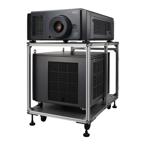
- Page 1 DLP Cinema Projector ® Installation Manual DLP Cinema Projector ® NC1700L Chiller Unit NP-17CU01 Model No. NP-NC1700L...
-
Page 2: Introduction
DLP Cinema Projector Installation and Adjustment NEC Display Solutions, Ltd. Manual (This document) describes the proce- dures to install, adjust and maintain the projector (NC1700L), the chiller unit (NP-17CU01) and peripheral devices. For safe and correct installation, adjustment and use of the projector, carefully read this document before installation. -
Page 3: Important Information
Important Information Precautions: Please read this manual carefully before using Laser Safety Caution your NC1700L and keep the manual handy for future This product is classified as Class 1 of IEC60825-1 Third edi- reference. tion 2014. This product is classified as RG3 of IEC62471-5 The NC1700L (projector unit) is called the “projector”, the... - Page 4 NO USER SERVICEABLE PARTS. power plug is disconnected from the outlet MAINTAIN AND SERVICE OF THE PRODUCT IS ONLY TO • That the connector cable and hose that connects the BE HANDLED BY NEC AUTHORIZED TECHNICIANS. device to the projector is unplugged...
- Page 5 Important Information 3. Handle the power cable carefully. A damaged or frayed WARNING power cable can cause electric shock or fire. • Do not bend or tug the power cable excessively. 1. Do not cover the lens with the supplied lens cap or •...
- Page 6 Important Information 2. Prevent foreign objects such as paper clips and bits of CAUTION paper from falling into your projector. Do not attempt to retrieve any objects that might fall into your projector. Do 1. Do not unplug the power cable from the wall outlet or not insert any metal objects such as a wire or screwdriver projector when the projector is powered on.
- Page 7 Fax Line: +49 89 99699 500 Email Address: info@nec-displays.com WEB Address: http://www.nec-display-solutions.com In North America Company Name: NEC Display Solutions of America, Inc. Address: 500 Park Boulevard, Suite 1100 Itasca, Illinois 60143, U.S.A. Telephone: +1 800 836 0655 Fax Line: +1 800 356 2415 Email Address: pjtechsupport@necdisplay.com...
- Page 8 Important Information In China Company Name: NEC Solutions (China) Co., Ltd. Address: Rm 1903, Shining Building, 35 Xueyuan Rd, Haidian District Beijing 100191, P.R.C. Telephone: +8610-4008-900-678 Email Address: nec-support@nec.cn In Hong Kong and Taiwan Company Name: Strong Westrex, Inc. Address: Room 4108 China Resources Building, No. 26...
- Page 9 Important Information Laser Aperture Modules • The laser module is equipped in this product. Use of controls or adjustments of procedures other than those specified herein may lead to hazardous laser radiation exposure. • This product is classified as Class 4 of IEC60825-1 Second edition 2007. This product is classified as Class 1 of IEC60825-1 Third edition 2014.
- Page 10 Important Information Label B Label A Laser Aperture (Class4:IEC60825-1 2nd edition) Label A: Hazard Warning Symbol, Label B: Risk Group / Explanatory Label and Lamp Safety Label Aperture Label Hazard Warning Symbol Aperture Label Explanatory Label...
- Page 11 Important Information Label C Label E Label D Label C: Identification Label Certification Statement Label Label D Label E...
- Page 12 Important Information Laser light specifications Class Class 4 laser product Wavelength Blue: 450 - 460 nm, Red: 636 - 642 nm Maximum optical output Blue (450 - 460 nm): 800 mW, Red (636 - 642 nm): 890 mW Beam diameter 10 mm Divergence 2 Degree to 22 Degree, lens dependent...
- Page 13 Important Information Class 3B Class 1 Class 2 Class 3R Class 4 NP-9LS16ZM1 0.2m (Tele) (Wide) 0.1m 0.25m (Tele) 0.25m (Wide) 0.9m (Tele) 1.8m (Wide) 2.75m (Tele) Class 3B Class 1 Class 2 Class 3R Class 4 NP-9LS16Z1 0.1m (Wide) (Tele) 0.1m (Wide)
- Page 14 Important Information Class 3B Class 1 Class 2 Class 3R Class 4 NP-9LS20Z1 (Wide) 0.3m (Tele) 0.3m (Wide) 0.3m (Tele) 0.3m (Wide) 0.9m (Tele) 1.9m 3.8m (Wide) (Tele) 6.0m Class 3B Class 1 Class 2 Class 3R Class 4 NP-9LS40ZM1 NP-9LS40Z 0.3m (Wide) 0.3m (Tele)
- Page 15 Important Information Range of Laser Light Emissions The following range indicates the maximum range of emission of laser light. Horizon angle: H Vertical angle: V [Degree] [Degree] Zoom Zoom Lens Lens Tele Wide Tele Wide NP-9LS12ZM1 15.7 22.1 NP-9LS12ZM1 12.2 NP-9LS13ZM1 13.3 20.2...
- Page 16 Important Information Radiation Range of Emitted Light by the Projector (HD: Hazard Distance) • The below table describes the radiation range of emitted light by the projector that is classified as Risk Group 3 (RG3) of IEC62471. • Please keep within bounds for installing the projector. Install a barrier for preventing human eyes from entering the RG3 area.
- Page 17 Important Information CAUTION Please heed all precaution for safety. To install the projector • For planning the layout of the projector, make sure to take safety measures instructed on the installation manual. • In order to refuse danger, install either a wall outlet within easy reach for pulling out the power plug in emergency or a device as a breaker to shut down the power supply to the projector.
- Page 18 Important Information Radiation Range of Emitted Light by the Projector (HD: Hazard Distance) • The below table describes the radiation range of the MPE (Maximum Permissible Exposure) values of ANSI Z 136.1. • Please keep within bounds for installing the projector. Install a barrier for preventing human eyes or skin from entering irradiation area by laser radiation exceeding the MPE values.
- Page 19 69kg for long time. At the same time, pay enough attention not to intrude the secured safety zone caused on shifting the light emission. • Record the installation result onto the sheet at the end of this installation manual and submit it to NEC. This record is kept by the installation service agent and NEC.
-
Page 20: Wichtige Informationen
Wichtige Informationen Vorsichtsmaßnahmen: Lesen Sie sich dieses Handbuch Vorsichtsmaßnahmen zur Lasersicherheit bitte sorgfaltig durch, bevor Sie den NC1700L benutzen, und Dieses Produkt ist gemäß IEC60825-1 Dritte Auflage 2014 als bewahren Sie das Bedienungshandbuch in greifbarer Nahe Klasse 1 klassifiziert. Dieses Produkt ist als RG3 von als spätere Referenz auf. - Page 21 Sie unter „Über den Modus Große Höhe“ (Seite 24). ES GIBT KEINE VOM BENUTZER ZU WARTENDEN TEILE. 13. Schalten Sie den Projektor beim Entfernen und Einsetzen DIE WARTUNG DES PRODUKTS DARF NUR VON NEC- der Linsen aus. Die Nichtbeachtung dieser Vorschrift AUTORISIERTEN TECHNIKERN DURCHGEFÜHRT...
- Page 22 Wichtige Informationen Spannungsversorgung WARNUNG 1. Der Projektor wurde so konzipiert, dass er mit der unten 1. Bedecken Sie die Linse nicht mit der mitgelieferten Lin- aufgeführten Netzspannung läuft. senkape o.ä. wärend der Projektor eingeschaltet ist. • Projektor Dies kann eine Verformung oder ein Schmelzen der 200-240V Wechselstrom 10,7A(MAX) 50/60Hz Ein- Kappe verursachen.
- Page 23 Wichtige Informationen 4. Lichtkegel des Projektors fern. Da das von der Linse pro- ACHTUNG jizierte Licht umfassend ist, können alle abnormalen Gegenstände, die in der Lage sind, das aus der Linse Der nachfolgend abgebildete Netzkabelstopper wird mit austretende Licht umzulenken, unvorhersehbare Ereig- diesem Projektor mitgeliefert.
- Page 24 Wichtige Informationen Vorsicht beim Transportieren des Projektors/Umgang mit 4. Wenden Sie sich an einen qualifizierten Händler, wenn der optischen Linse Sie das Lichtmodul austauschen wollen oder weitere Informationen benötigen. Wenn Sie den Projektor mit der Linse verschicken, entfernen Sie die Linse vor dem Versand. Bringen Sie immer die Staub- schutzkappe an der Linse an, wenn diese nicht am Projektor Über den Modus Große Höhe angebracht ist.
- Page 25 E-Mail-Adresse: contact@goldenduckgroup.com Fax-Nummer: +49 89 99699 500 E-Mail-Adresse: info@nec-displays.com Web-Adresse: http://www.nec-display-solutions.com In Nordamerika Firmenname: NEC Display Solutions of America, Inc. Adresse: 500 Park Boulevard, Suite 1100 Itasca, Illinois 60143, U.S.A. Telefon: +1 800 836 0655 Fax-Nummer: +1 800 356 2415 E-Mail-Adresse: pjtechsupport@necdisplay.com...
- Page 26 Wichtige Informationen Laseraustrittsmodule • Das Lasermodul ist in dieses Gerät eingebaut. Die Verwendung von Bedienelementen oder die Änderung von Prozeduren in Abweichung von den in diesem Handbuch beschriebenen könnte zu gefährlichem Kontakt mit Laserstrahlung führen. • Dieses Produkt ist als Klasse 1 von IEC60825-1 Dritte Auflage 2014 eingestuft. Dieses Produkt ist als RG3 von IEC62471-5 Erste Ausgabe 2015 eingestuft.
- Page 27 Wichtige Informationen Aufkleber C Aufkleber E Aufkleber D Aufkleber C : Aufkleber mit Hersteller-ID Aufkleber D Aufkleber E...
- Page 28 Wichtige Informationen Strahlungsbereich des abgegebenen Lichts durch den Projektor (Sicherheitsabstand – HD: Hazard distance) • Die nachfolgend abgebildete Tabelle gibt den Strahlungsbereich des abgegebenen Lichts durch den Projektor an, das als Risikogruppe 3 (RG3) nach IEC62471 klassifiziert ist. • Bitte bei der Installation des Projektors die Einschränkungen beachten. Installieren Sie zum Schutz der menschlichen Augen vor dem RG3-Bereich eine Abdeckung.
- Page 29 Wichtige Informationen WARNUNG Bitte beachten Sie alle Sicherheitshinweise. Installation des Projektors • Beachten Sie bei der Planung des Aufbaus des Projektors die Sicherheitsmaßnahmen im Installationshandbuch. • Installieren Sie zur Gefahrenverringerung eine Wandsteckdose in Reichweite, damit der Netzstecker im Notfall heraus- gezogen werden kann, oder einen Trennschalter, um die Stromversorgung zum Projektor unterbrechen zu können.
- Page 30 Table of Contents Introduction ..................................2 Important Information ................................ 3 Wichtige Informationen ..............................20 1. Before Setting Up Your Projector and the Chiller Unit ....32 1-1. Clearance for Installing the Projector and the Chiller Unit (English) ..............32 1-1-1. Projector ............................... 32 1-1-2.
- Page 31 Table of Contents 4. LCD Menu .................. 89 4-1. List of Menu ................................89 4-1-1. When You Use the Service Personnel Menu ....................90 4-2. Title Select ................................91 4-2-1. Title select (Title Memory) ........................... 91 4-2-2. Test Pattern ..............................91 4-3.
-
Page 32: Before Setting Up Your Projector And The Chiller Unit
1. Before Setting Up Your Projector and the Chiller Unit 1-1. Clearance for Installing the Projector and the Chiller Unit (English) Allow ample clearance between the projector and its surroundings as shown below. Avoid installing the projector in a place where air movement from the HVAC is directed at the projector. Heated air from the HVAC can be taken in by the projector’s intake vent. -
Page 33: Installation Conditions For The Chiller Unit
Before Setting Up Your Projector and the Chiller Unit (2) For rack installation • When using a rack, do not store the projector in a case or the like. 70cm/27.6" or greater REMOTE RS-232 GP I/O Lens Rack 1-1-2. Installation Conditions for the Chiller Unit •... - Page 34 Before Setting Up Your Projector and the Chiller Unit • Avoid placing the projector and chiller unit in such a way in which any air inlet and any outlet of them face each other. Air outlet Air outlet Air inlet Air inlet Air inlet Air outlet...
-
Page 35: Umgebung Und Abstände Beim Aufbau Des Geräts (Deutsch)
Before Setting Up Your Projector and the Chiller Unit 1-2. Umgebung und Abstände beim Aufbau des Geräts (Deutsch) Achten Sie auf ausreichenden Freiraum zwischen dem Projektor und seiner Umgebung, wie unten gezeigt. Vermeiden Sie es, den Projektor an einer Stelle zu installieren, an der er den Luftströmungen von Klimaanlagen ausgesetzt ist. Die aufgeheizte Luft aus einer Klimaanlage kann vom Lüftungseinlass des Projektors aufgenommen werden. -
Page 36: Aufbau Der Wasserkühleinheit
Before Setting Up Your Projector and the Chiller Unit (2) Aufbau auf ein Gestell - Legen Sie das Gerät nicht in einen Behälter, wenn Sie ein Gestell verwenden. mehr als 70 cm REMOTE RS-232 GP I/O Linse Gestell 1-2-2. Aufbau der Wasserkühleinheit •... - Page 37 Before Setting Up Your Projector and the Chiller Unit • Achten Sie darauf, dass sich Lufteinlass und Luftauslass der Wasserkühleinheit nicht gegenseitig stören, wenn Sie den Projektor aufbauen. Luftauslass Luftauslass Lufteinlass Lufteinlass Lufteinlass Luftauslass Lufteinlass...
-
Page 38: Selecting The Lens Unit
Before Setting Up Your Projector and the Chiller Unit 1-3. Selecting the lens unit This section provides the guideline information on how to select a screen size, projector mounting position, and type of lens units, which is appropriate for your presentation purposes. Select the lens unit for your projector according to the environment in which it is installed. - Page 39 Before Setting Up Your Projector and the Chiller Unit Vertical moving screen mask Screen masks move vertically to adjust the screen. Screen mask Screen Screen mask...
-
Page 40: Calculating The Lens Zoom Magnification To Use
Before Setting Up Your Projector and the Chiller Unit 1-3-2. Calculating the lens zoom magnification to use The lens zoom magnification required when installing the projector is calculated using the following method. (1) Calculate the lens zoom magnification for SCOPE projection (2) Calculate the lens zoom magnification for VISTA (FLAT) and HDTV projection (3) Select the lens that satisfies the zoom magnification calculated in (1) and (2). - Page 41 Before Setting Up Your Projector and the Chiller Unit Option lenses The lens units that can be attached to this projector are shown in the following table. MODEL Magnifying Lens memory support NP-9LS16Z1 1.63–2.03 NP-9LS20Z1 2.03–2.72 NP-9LS12ZM1 1.2–1.72 NP-9LS13ZM1 1.33–2.1 ...
-
Page 42: Carrying The Projector
Before Setting Up Your Projector and the Chiller Unit 1-4. Carrying the projector When moving the projector, it should be carried by holding the handles on the base of the unit by 4 or more people. WARNING When moving the projector, first turn off the power and always disconnect the power plug from the electrical outlet, and check that all of the connecting cables between equipment and the lenses have been removed. -
Page 43: Removing The Projector Covers
Before Setting Up Your Projector and the Chiller Unit 1-5. Removing the Projector Covers This section provides guideline information on how to mount and remove covers on the projector. Name of the cover Front cover Side cover Air inlet cover •... - Page 44 Before Setting Up Your Projector and the Chiller Unit Front Cover The lock is unlocked when attaching or removing lenses (page 57). Top Cover Removing and attaching the cover is performed by a trained service engineer. The lock should only be unlocked by service engineers.
-
Page 45: Removing And Mounting The Front Cover
Before Setting Up Your Projector and the Chiller Unit 1-5-1. Removing and Mounting the Front Cover When removing (mounting) the front cover, return the lens position to the center before turning off the projector NOTE power (page 100). If you do not return the lens position to the center, the lens may interfere and prevent you from removing (mounting) the front cover. - Page 46 Before Setting Up Your Projector and the Chiller Unit Unlock the front cover. Unlock the cover using the cover key. Key lock Remove the front cover. Hold the bottom left of the cover ( ) with your left hand and the base of the lens hood ( ) with your right hand, and pull the cover directly towards you to remove it.
-
Page 47: Removing And Mounting The Side Cover
Before Setting Up Your Projector and the Chiller Unit 1-5-2. Removing and Mounting the Side Cover Preparation: Phillips head screwdriver (No.2) and cover key (attached goods) Loosen the four fixing screws on the side cover. Loosen four screws on the side cover until they are free to spin. The screws do not detach from the cover. REMOTE RS-232 GP I/O... - Page 48 Before Setting Up Your Projector and the Chiller Unit Remove the side cover. The bottom part of the side cover is fixed in place by hooks (in 3 locations). Remove it by using the following procedure. 1. Hold the upper part and the left and right edges of the side cover and pull it towards you. There is a handhold on the left side of the side cover.
-
Page 49: Setup Procedure
2. Setting Up Your Projector and Chiller Unit 2-1. Setup Procedure Set up the projector and the chiller unit according to the procedure below. This chapter describes the installation of procedure until turning on of the power. Projector • Step 1 Projector Installation (See page 50) •... -
Page 50: Projector Installation
Setting Up Your Projector and Chiller Unit 2-2. Projector Installation Move the projector to the projection position and install it corresponding to the screen and projection conditions. To correct the inclination to the right or left of the projector, use the level adjusters at 4 positions. You can extend the level adjuster to 35 mm at the maximum (Rotate it counterclockwise for extension). -
Page 51: Selecting The Power Cable (Projector) (English)
Setting Up Your Projector and Chiller Unit 2-3. Selecting the Power Cable (Projector) (English) The power cable is not included with the projector. Refer to “2-3-1. AC Power Work Specifications (Projector)” (page 52) and provide the necessary power cable. WARNING Carefully read the contents described in this section before connection and connect the cables according to the proper procedure. -
Page 52: Ac Power Work Specifications (Projector)
Setting Up Your Projector and Chiller Unit 2-3-1. AC Power Work Specifications (Projector) AC power supply equipment Do not use any voltage other than those shown below for the AC power supply connected to the projector. 200–240V AC, single phase, power, 50/60Hz AC power supply cable for the projector The projector is equipped with an IEC60320 C20 inlet to connect an AC power supply cable. - Page 53 Setting Up Your Projector and Chiller Unit China Plug Cable Connector GB2099 RVV 300/500 GB17465.1 Connector Dimensions of the connector of the power cable are shown below. -0,9 -0,7 ± +0,5 + 0,5 R3.5 min + 0,5 Unit: mm...
-
Page 54: Auswahl Des Netzkabels (Projektor) (Deutsch)
Setting Up Your Projector and Chiller Unit 2-4. Auswahl des Netzkabels (Projektor) (Deutsch) Es wird kein Netzkabel mit dem Projektor geliefert. Nehmen Sie auf „2-4-1. Netzstrom-Spezifikationen (Projektor)“ (Seite 55) Bezug, und beschaffen Sie das notwendige Netzkabel. WARNUNG Lesen Sie diesen Abschnitt vor dem Herstellen der Verbindungen sorgfältig durch, und schließen Sie die Kabel anhand der ordnungsgemäßen Verfahren an. -
Page 55: Netzstrom-Spezifikationen (Projektor)
Setting Up Your Projector and Chiller Unit 2-4-1. Netzstrom-Spezifikationen (Projektor) Netzkabel Der Projektor ist mit einem C19-Steckverbinder gemäß IEC60320 zum Anschließen des Netzkabels ausgestattet. Sorgen Sie dafür, dass die Netzkabel, die von den Steckverbindern am Projektor zum Netzanschluss führen, über die unten angegebenen Stromkapazitäten verfügen. - Page 56 Setting Up Your Projector and Chiller Unit Japan Stecker Kabel Steckverbinder JIS C 8303 VCTF 3 x 2.0mm IEC 320 C19 China Stecker Kabel Steckverbinder GB2099 RVV 300/500 GB17465.1 Steckverbinder Die Abmessungen des Netzkabels sind unten angegeben. -0,9 -0,7 ± +0,5 + 0,5 R3,5 Min...
-
Page 57: Mounting The Lens Unit
NP-9LS40ZM1 4.07–6.34 • The other NEC optional lenses are not available on this model. NOTE • The projector and lenses are made of precision parts. Do not subject them to shock or excessive forces. • Remove the lens unit when moving the projector. If not, the lens could be subject to shock while the projector is being moved, damaging the lens and the lens shift mechanism. - Page 58 Setting Up Your Projector and Chiller Unit Orient so that the connector on the lens unit is on the right side, then insert the lens into the projector. Orient so that the connector on the lens unit is on the right side Turn the lens clockwise.
-
Page 59: Removing The Lens
Setting Up Your Projector and Chiller Unit 2-5-1. Removing the lens Preparation: [1] Return to the center position. (page 100) [2] Turn off the main power and unplug the power cable. [3] Wait for the projector to cool sufficiently before removing the lens, before removing the front cover. (page Rotate the lens counterclockwise while holding down the RELEASE LEVER. -
Page 60: Mounting The Option Board
Setting Up Your Projector and Chiller Unit 2-6. Mounting the Option Board This section describes the procedure of mounting the option board. The following option board can be mounted to the slot of the projector. Name Slot NP-90MS02-4K Preparation: Phillips head screwdriver (No.2) and cover key (attached goods). •... - Page 61 Setting Up Your Projector and Chiller Unit Remove the side cover. Side cover of the projector should be removed to mount the option board. For the procedure of removing the side cover, refer to “1-5-2. Removing and Mounting the Side Cover” (page 47). Remove the blocking panel from slot.
-
Page 62: Make The Option Board Usable
Setting Up Your Projector and Chiller Unit 2-6-1. Make the option board usable By registering the mounted option board to the slot, you can use option board by setting up the projector. This procedure is described for the example, when IMB (NP-90MS02-4K) is mounted to slot. For the operation of the projector, refer to projector’s “Users Manual”. - Page 63 Setting Up Your Projector and Chiller Unit Press the LEFT/RIGHT button to display “IMB” . Press the ENTER button. (*) is displayed to the selected item. Press the EXIT button several times. The projector exits the menu and goes back to the regular screen. If you press the EXIT button and then select “Yes”...
-
Page 64: Connecting The Power Cable For The Chiller Unit
Setting Up Your Projector and Chiller Unit 2-7. Connecting the Power Cable for the Chiller Unit The power cable is not included with the chiller unit. Refer to “2-7-1. AC Power Work Specifications (Chiller Unit)” (page 65) and provide the necessary power cable. WARNING Carefully read the contents described in this section before connection and connect the cables according to the proper procedure. -
Page 65: Ac Power Work Specifications (Chiller Unit)
Setting Up Your Projector and Chiller Unit 2-7-1. AC Power Work Specifications (Chiller Unit) AC power facilities Do not use the AC power supply connected to the chiller unit outside of the voltage range illustrated below. AC 200V-240V 50Hz Single phase AC 220V-240V 60Hz Single phase Breaker Connect the AC power supply from the power supply equipment of the building to the chiller unit via a breaker. - Page 66 Setting Up Your Projector and Chiller Unit Compatible Cables and Solderless Terminals Power terminal L, N Ground terminal G Solderless terminals and screw fastening torques compatible with the terminal block are specified below. This specifies the model name of the recommended solderless terminals. Use these parts or equivalent parts. If you are unable to use the recom- mended solderless terminals, ensure that you use terminals of the dimensions shown in the following diagram.
- Page 67 Setting Up Your Projector and Chiller Unit • Ground terminal (Green / Yellow) Standards Item IEC/EN CSA (C-UL) Thickness of compatible wiring 2.0 mm AWG14 Solderless terminal dimensions Tightening torque 0.6 to 0.8 N•m Solderless terminal dimensions Min. φ3.7 Max 6.8 Max.
- Page 68 Setting Up Your Projector and Chiller Unit Connecting the Cable In order to attach the power cable to the connector block, connect the wires using the following procedure such that the indi- vidual wires cannot directly touch each other. Remove the power cable sleeves from the terminals to Sleeves ensure that the sleeves are not pinched by the terminal attachment screw.
-
Page 69: Connecting The Ac Power Cable To The Chiller Unit
Setting Up Your Projector and Chiller Unit 2-7-2. Connecting the AC Power Cable to the Chiller Unit Preparation: Phillips head screwdriver, flatblade screwdriver (No.2) WARNING Check that the AC power supply is disconnected before connecting the power cable to the chiller unit. If connected, this may cause fire or shock. - Page 70 Setting Up Your Projector and Chiller Unit Raise the arm of the ground terminal. Loosen the grounding terminal screw with a flathead screwdriver and lift the arm. Screw Insert the ground cable into the ground terminal. Insert the crimp terminal of the ground cable to the connecting terminal of the ground terminal. Connecting terminal WARNING Firmly tighten the ground cable to the connecting terminal.
-
Page 71: Connecting The Hoses For The Chiller Unit And Control Cable
Setting Up Your Projector and Chiller Unit 2-8. Connecting the Hoses for the Chiller Unit and Control Cable Connect the hoses for the chiller unit between the projector and chiller unit. After connecting the hoses for the chiller unit, connect the control cable to monitor the state of the chiller unit and control ON/OFF of the unit from the projector. WARNING Carefully read the contents described in this section before connection and connect the cables according to the proper procedure. - Page 72 Setting Up Your Projector and Chiller Unit Connect the hose attachment port (IN) on the projector and the coolant outlet of chiller (OUT) on the chiller unit with a hose for the chiller unit supplied as an accessory. Securely insert the hose all the way in. To disconnect the hose, push the button at each end of the hose and pull out the hose.
-
Page 73: Connecting The Control Cable
Setting Up Your Projector and Chiller Unit 2-8-2. Connecting the Control Cable To monitor the state of the chiller unit and control ON/OFF of the unit from the projector, connect the control cable. Connect the chiller unit control port (RJ-45) on the projector and the connector for communica- tion line (RJ-45) on the chiller unit with the control cable supplied as an accessory. -
Page 74: Pouring And Draining The Coolant
Setting Up Your Projector and Chiller Unit 2-9. Pouring and Draining the Coolant Coolant uses a dedicated NP-17AL01 (option). WARNING • Before pouring or draining, check that the main power switches of the projector and chiller unit are turned off. Pour or drain the coolant with AC power shut off. -
Page 75: Draining The Coolant
Setting Up Your Projector and Chiller Unit 2-9-2. Draining the Coolant Preparation: Phillips head screwdriver (No.2), container Remove the screw for securing the cover with a Phillips head screwdriver and remove the cover. Pull out the drain port. Cover Place a container for receiving the coolant under the drain port. (Amount of coolant: About 12 liters at maximum) Open the valve of the drain port and drain the coolant in the tank. -
Page 76: Setting The Chiller Unit
Setting Up Your Projector and Chiller Unit 2-10. Setting the Chiller Unit 2-10-1. Setting the Temperature of the Coolant To change the setting of the temperature of the coolant, use the Temp. controller on the chiller unit. The temperature is factory- set to 18°C. -
Page 77: Fixing The Chiller Unit
Setting Up Your Projector and Chiller Unit If an error occurs in the chiller unit, one of the following error codes is displayed on the status display. NOTE Turn off the projector and the chiller unit, Inquire your dealer about action to be taken for each error code. •... -
Page 78: Projector Adjustment And Connecting
3. Projector Adjustment and Connecting 3-1. Flow of Adjustment and Connecting Adjustment and Connecting of the projector accord to the procedure below. • Step1 Turning Your Projector On (See page 82) • Step2 Setting The Date and Time in the Projector (See page 82) •... -
Page 79: Recovering From Tamper Errors
Projector Adjustment and Connecting 3-2. Recovering from Tamper Errors The tamper detection circuit is fitted in the projector. If any of the following actions is performed, an error message will be displayed on the LCD screen of the main unit control panel by tamper detection circuit. -
Page 80: Clearing Tamper Events
Projector Adjustment and Connecting 3-2-1. Clearing tamper events Be sure to do this while the power of the projector is on (when Power-ON). If any tamper events have been detected by the tamper detection circuit of the projector main unit, clear the tamper events using the following procedure. - Page 81 Projector Adjustment and Connecting • Step 1 “Clear the “Service Door Tamper” by using the buttons on the Control Panel.” Refer to “4-1-1. When You Use the Service Personnel Menu” (page 90) for details on logging into the projector with Advanced User or higher privileges using the buttons on the control panel.
-
Page 82: Turning Your Projector On
Projector Adjustment and Connecting 3-3. Turning your Projector On • Do not use the projector with the lens cap left attached, and do not attach the lens cap while the projector is NOTE operating. The lens cap may become hot, causing them to deform or melt. •... -
Page 83: Setting The Projector Projection Method
Projector Adjustment and Connecting 3-5. Setting the Projector Projection Method The projection method can be changed in the projector menu. In the factory default settings, it is set to front (installed on a stand and projecting from the front of the screen). Press the MENU button for three seconds or longer. -
Page 84: Adjusting The Lens
Projector Adjustment and Connecting 3-6. Adjusting the Lens After attaching the lens unit, check that the lens type is set correctly. Furthermore, if you have attached a lens unit that supports the lens memory function, always execute calibration before adjusting the lens. After this, display the test pattern and adjust the screen size, focus and screen position with the lens unit. -
Page 85: Display The Test Pattern
Projector Adjustment and Connecting 3-6-2. Carry out Calibration of the Lens If you have attached a lens unit that supports the lens memory function, always execute calibration before making adjustments. Preparation: • Check that the lens is attached correctly (page 57). •... -
Page 86: Adjusting The Screen Angle
Projector Adjustment and Connecting 3-6-4. Adjusting the Screen Angle Preparation: Display the zoom/focus adjustment screen by using the following procedure. [1] Press the MENU button on the projector’s control panel. “Title Select” appears on the projector’s LC display. [2] Select “Configuration” menu using LEFT the LEFT/RIGHT button. [3] Press the DOWN button. -
Page 87: Connecting With The Image Input Port
Projector Adjustment and Connecting 3-7. Connecting with the Image Input Port By installing option board to projector, you can add input port. Input port which can add to option board is listed below. For the connection diagram of projector and peripheral equipment, refer to Installation manual of option board. Option Board Image Input Port NP-90MS02-4K (Note) -
Page 88: Connecting The Various Control Terminal
Projector Adjustment and Connecting 3-8. Connecting the Various Control Terminal For control, your projector comes with such ports as the PC control terminal and the Ethernet port (RJ-45). PC control terminal (RS-232) Use this terminal when controlling the projector in serial connection from a PC. Use a retail RS-232C straight cable for the connection between the projector and the computer. -
Page 89: Lcd Menu
4. LCD Menu This chapter describes the menus displayed in the LCD screen on the projector’s control panel and their functions. For basic operations of menus, refer to the projector’s operation manual. 4-1. List of Menu Menus in parentheses are menus for our service personnel. Normally, these menus cannot be used. If you are logged in to the projector with Installation privileges, you cannot use [FactoryDefault] - [LAN] (page 93). -
Page 90: When You Use The Service Personnel Menu
LCD Menu Reference Main menu Submenu Description page Installation (Sensor Calib.) Calibrate the sensors upon installation. (Note) Configuration (Memory) Light The content of the selected light memory (light output power value) can be overwritten with the current settings. Lens The content of the selected lens memory can be overwritten with the current settings. -
Page 91: Title Select
LCD Menu 4-2. Title Select 4-2-1. Title select (Title Memory) Select the title of the signal to be projected. You can register up to 100 titles. You can also assign registered titles to the preset buttons <1> to <8> on the projector’s control panel and call them up directly using those buttons. -
Page 92: Lens Control
LCD Menu 4-3. Configuration 4-3-1. Light Setup Adjust Adjusts the light source brightness (output). This setting is the fraction based on taking the maximum value of light source brightness as 100%. ← Adjusts the output power value (%). 4-3-2. Lens Control Adjust the position, size, and focus of the projected screen. -
Page 93: Reset
LCD Menu 4-3-3. Reset Used when initializing settings and usage times. Some of the items are in the service personnel menu. Refer to “4-1-1. When You Use the Service Personnel Menu” (page 90) for details on how to use these. Item Service Personnel User... - Page 94 LCD Menu Fan Usage Resets the fan usage time. Press the ENTER button, then select “Yes” in the displayed confirmation screen, and then press the ENTER button to reset the fan usage time. ← Press the ENTER button to display the confirmation screen. Light Reset the light source usage time.
-
Page 95: Setup
LCD Menu Chiller Fan Resets the chiller unit fan usage time. Press the ENTER button, then select “Yes” in the displayed confirmation screen, and then press the ENTER button to reset the chiller unit fan usage time. ← Press the ENTER button to display the confirmation screen. Douser Count Resets the number of times the douser has been used. - Page 96 LCD Menu Panel Key Lock The control buttons on your projector are locked to be inoperative. ← Displays the currently selected item with asterisk (*). ← Displays the setting. Lock Enable a lock on the control buttons on your projector. Unlock Disable the lock on the control buttons.
- Page 97 LCD Menu Off Timer Automatically turns off the projector power once the configured time has elapsed. The time until the power is turned off can be set in steps of 1 hour (up to a maximum of 24 hours). The timer starts from when the setting is applied by pressing the ENTER button.
- Page 98 LCD Menu Silent Mode Sets whether the status indicators (SYSTEM status indicator, LIGHT status indicator), buzzer, indicators on the projector’s control panel, illumination, and LCD screen backlight are enabled or disabled. ← Selects the item. ← Displays the currently selected item with asterisk (*). ←...
-
Page 99: Installation
LCD Menu 4-3-5. Installation This menu is the service personnel menu. For the using service personnel menu, refer to “4-1-1. When You Use the Service Personnel Menu” (page 90). Option Slot Configures the devices mounted in slot. This menu is active in standby mode only. Slot B is not available in this projector (displays as “Not Available”). - Page 100 LCD Menu Lens Type Sets the type of lens (supports or does not support the lens memory function) attached to the projector. This menu item is available only when you are logged into the projector with Advanced User or higher privileges. ←...
- Page 101 LCD Menu Baudrate To select the transmission speed (bps) for your projector (SYSTEM) and a PC when they are connected by a commercially available RS-232C straight cable. Select one from 4800, 9600, 19200 and 38400. Select the transfer speed corresponding to the speed of the connected devices.
- Page 102 LCD Menu Fan Speed Mode It adjusts the rotation speed of the internal cooling fan. ← Displays the currently selected item with asterisk (*). ← Displays the setting. Auto The fan rotates at the optimal speed according to the temperature sensor inside the projector. High Speed The fan always rotates at high speed.
-
Page 103: Memory
LCD Menu 4-3-6. Memory This menu is the service personnel menu. For the using service personnel menu, refer to “4-1-1. When You Use the Service Personnel Menu” (page 90). The selected lens memory (lens adjustment value) and the content of the light memory (light output power value) can be overwritten with the current settings. -
Page 104: Title Setup
LCD Menu 4-4. Title Setup This menu is the service personnel menu. For the using service personnel menu, refer to “4-1-1. When You Use the Service Personnel Menu” (page 90). 4-4-1. Preset Button Use this button to set the titles to be assigned to the preset buttons (<1> to <8> buttons). You cannot assign the same title to several preset buttons. -
Page 105: Light Output
LCD Menu 4-5. Information Displays information relating to the light source, the usage time of the projector, the version information and error codes. 4-5-1. Light Output Displays the value of the light source output setting (%). ← Displays the current setting (%). 4-5-2. -
Page 106: Error Code
LCD Menu 4-5-4. Usage Displays information related to the projector usage, such as the usage time of the projector, light, air filters, and fan, and infor- mation about the light replacement cycle. ← Selects the item to display. ← Displays information about the selected item. Projector Displays the usage time of the projector. -
Page 107: Version
LCD Menu 4-5-6. Version Displays version information about the projector, optional boards, and IMB. System Displays the version information of the projector. ← Selects the item to display. ← Displays the version information. • Model • Serial No. • Release Package •... -
Page 108: Setup Date
LCD Menu 4-5-8. Setup Date Displays the date when the projector was setup (starting date of the warranty period). The setup date is configured by using DCC. Refer to “Digital Cinema Communicator for S2 Installation Manual” for details. ← Displays the date when the projector was set up (starting date of the warranty period). 4-5-9. -
Page 109: Appendix
5. Appendix 5-1. List of Registered Titles (when shipped from the factory) -
Page 110: Error Code List
Appendix 5-2. Error Code List Please inquire your dealer/distributor about action to be taken for each error code. Error Code Error message Description GPSU(12V) Fail Power supply is abnormal. Light Unlit The light source is not on. EEPROM R Fail EEPROM data read error is detected. - Page 111 Appendix Error Code Error message Description Fan12 Stop Precaution Fan12 Stop Precaution Fan13 Stop Precaution Fan13 Stop Precaution Fan14 Stop Precaution Fan14 Stop Precaution IMB:SD Tamper Terminate Terminated service door tamper event latched by IMB. * This message would be shown on Log, not on LCD. System Error ICP status error Self Test Error...
- Page 112 Appendix Error Code Error message Description IMB:Security Battery Event A Battery Tamper event has been detected with the IMB. IMB:Security Enclosure Not Armed IMB security not armed. IMB:Physical Marriage Tamper The IMB has detected a break of the Marriage with the projector.
- Page 113 Appendix Error Code Error message Description LaserBDEepromFail Data check sum error in EEPROM on LD board. LDMCULockUp LD uC is locked up. 54VError 54V is abnormal. LDEepromFail Communication error with the EEPROM on LD board. KEY Switch Off The laser unit laser administrator switch is off. 1000 Slave Comm Fail Failed to communicate with slave MCU.
- Page 114 Appendix Error Code Error message Description 2134 SensorFail LS_B_Module Failed to read LS_B_Module sensor. 2135 SensorFail LS_R_String Failed to read LS_R_String sensor. 2140 Chiller On Fail Failed to turn on chiller 2141 Chiller Pump over loading Chiller Pump is abnormal. 2142 Chiller Compressor over loading Chiller Compressor is abnormal.
-
Page 115: Remote Interlock Connector
Appendix 5-3. Remote Interlock Connector This connector functions as safety device for the projector. The contacts are normally closed. When an abnormality occurs, the contacts open to immediately stop the projector (interlock state) (shipped with a shorting wire installed). By replacing the shorting wire with wiring and attaching it to the contacts, the projector can be immediately stopped remotely when an abnormality occurs in the projector. - Page 116 Appendix Circuit diagram Interlock connector Inside projector Shorting wire 2 390Ω/0.5W resistor 390Ω/0.5W resistor Photocoupler Shorting wire 1 100mA fuse VCC +5V Connector no. Photocoupler ON/OFF Description — +5V supply ON/OFF Connects to the photocoupler anode inside the projector Connects to the photocoupler cathode inside the projector —...
-
Page 117: Index
Appendix 5-4. Index Numbers 3D Connector ..............96 Image Orient ............... 99 IMB ..............60, 99, 107, 108 Information ................ 105 Installation ................99 IP Address ................ 107 Adjust .................. 92 Auto Key Lock ..............96 Key lock ................43 Baudrate ................101 LCD menu ................ - Page 118 Appendix Phosphor ................94 Power cable ................ 51 Power Cable for the Chiller Unit .......... 64 Preset Button ............104, 105 Projection method ............... 83 Projector cover ..............43 Remote interlock connector ..........115 Reset .................. 93 RS-232 ................88 Sensor Calib..............102 Service Adj.
- Page 119 © NEC Display Solutions, Ltd. 2017 Ver. 1.0 4/17...