Mitsubishi Electric PLFY-P20VEM-E Technical & Service Manual
City multi plfy series split-type, heat pump air conditioners
Hide thumbs
Also See for PLFY-P20VEM-E:
- Installation manual (18 pages) ,
- Installation manual (17 pages) ,
- Operation manual (20 pages)
Table of Contents
Advertisement
SPLIT-TYPE, HEAT PUMP AIR CONDITIONERS
TECHNICAL & SERVICE MANUAL
Indoor unit
[Model names]
PLFY-P20VEM-E
PLFY-P25VEM-E
PLFY-P32VEM-E
PLFY-P40VEM-E
PLFY-P50VEM-E
PLFY-P63VEM-E
PLFY-P80VEM-E
PLFY-P100VEM-E
PLFY-P125VEM-E
Grille model
[Model names]
PLP-6EA
PLP-6EAE
PLP-6EAL
PLP-6EALE
PLP-6EAJ
PLP-6EAJE
PLP-6EALM
PLP-6EALME
Model name
indication for
MAIN UNIT
INDOOR UNIT
WIRELESS REMOTE
CONTROLLER
(Option)
[Service Ref.]
PLFY-P20VEM-E.UK
PLFY-P25VEM-E.UK
PLFY-P32VEM-E.UK
PLFY-P40VEM-E.UK
PLFY-P50VEM-E.UK
PLFY-P63VEM-E.UK
PLFY-P80VEM-E.UK
PLFY-P100VEM-E.UK
PLFY-P125VEM-E.UK
[Service Ref.]
PLP-6EA
PLP-6EAE
PLP-6EAL
PLP-6EALE
PLP-6EAJ
PLP-6EAJE
PLP-6EALM
PLP-6EALME
Model name
indication for GRILLE
WIRED REMOTE
CONTROLLER
(Option)
PLP-6EAR1
PLP-6EAER1
PLP-6EALR1
PLP-6EALER1
CONTENTS
1. SAFETY PRECAUTION .......................... 2
2. PARTS NAMES AND FUNCTIONS ........ 4
3. SPECIFICATIONS ................................. 11
4. 4-WAY AIR FLOW SYSTEM ................. 16
5. OUTLINES AND DIMENSIONS ............ 19
6. WIRING DIAGRAM ............................... 20
7. REFRIGERANT SYSTEM DIAGRAM ...... 21
8. TROUBLESHOOTING .......................... 22
9. SPECIAL FUNCTION ........................... 30
10. DISASSEMBLY PROCEDURE ............. 33
PARTS CATALOG (OCB657)
December 2016
No. OCH657
Notes:
• This manual describes service
data of the indoor units only.
• RoHS compliant products have
<G> mark on the spec name
plate.
Advertisement
Table of Contents

Related Manuals for Mitsubishi Electric PLFY-P20VEM-E


Summary of Contents for Mitsubishi Electric PLFY-P20VEM-E
-
Page 1: Table Of Contents
SPLIT-TYPE, HEAT PUMP AIR CONDITIONERS December 2016 No. OCH657 TECHNICAL & SERVICE MANUAL Indoor unit [Model names] [Service Ref.] PLFY-P20VEM-E.UK PLFY-P20VEM-E Notes: • This manual describes service PLFY-P25VEM-E.UK PLFY-P25VEM-E data of the indoor units only. PLFY-P32VEM-E.UK PLFY-P32VEM-E • RoHS compliant products have <G>... -
Page 2: Safety Precaution
SAFETY PRECAUTION Cautions for units utilizing refrigerant R410A Use a vacuum pump with a reverse flow check Do not use the existing refrigerant piping. valve. The old refrigerant and lubricant in the existing piping Vacuum pump oil may flow back into refrigerant cycle and contain a large amount of chlorine which may cause the that can cause deterioration of refrigerant oil etc. - Page 3 [1] Cautions for service (1) Perform service after recovering the refrigerant left in unit completely. (2) Do not release refrigerant in the air. (3) After completing service, charge the cycle with specified amount of refrigerant. (4) When performing service, install a filter drier simultaneously. Be sure to use a filter drier for new refrigerant.
-
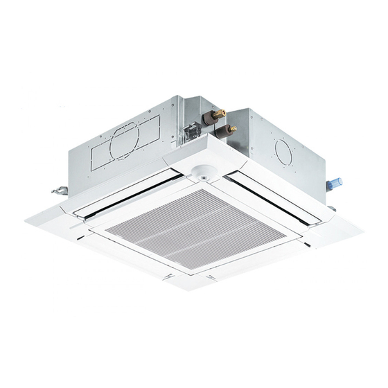
Page 4: Parts Names And Functions
PARTS NAMES AND FUNCTIONS 2-1. Indoor unit Drain pipe Air outlet Filter Liquid pipe Gas pipe Signal receiver i-see Sensor (Option) (Option) Vane Air intake (Intake grille) OCH657... - Page 5 2-2. WIRED REMOTE CONTROLLER <PAR-32MAA> Wired remote controller function The functions of the function buttons change depending on the screen. Refer to the button function guide that appears at the bottom of the LCD for the functions they serve on a given screen.
-
Page 6: Basic Mode
Room Set temp. Cool Auto Mode Temp. The main display can be displayed in 2 different modes: "Full" and "Basic". The factory setting is "Full". To switch to the "Basic" mode, change the setting on the Main display setting. <Full mode> <Basic mode>... - Page 7 Menu structure Press the button. MENU Main menu Move the cursor to the desired item with the buttons, and press the button. SELECT Vane · Louver · Vent. (Lossnay) High power Timer ON/OFF timer Auto-Off timer Weekly timer OU silent mode Restriction Temp.
- Page 8 Main menu list Setting and display items Setting details Vane · Louver · Vent. Use to set the vane angle. (Lossnay) • Select a desired vane setting from 5 different settings. Use to turn ON/OFF the louver. • Select a desired setting from "ON" and "OFF." Use to set the amount of ventilation.
- Page 9 Setting and display items Setting details Initial setting Main/Sub When connecting 2 remote controllers, one of them needs to be designated as a sub controller. Clock Use to set the current time. Main display Use to switch between "Full" and "Basic" modes for the Main display. •...
-
Page 10: Wireless Remote Controller
2-3. Wireless remote controller Transmission area Not available Remote controller display Battery replacement indicator Set Temperature buttons OFF/ON button Mode button (Changes operation mode) Fan Speed button (Changes fan speed) Airflow button (Changes up/down airflow direction) i-see button Timer ON button Menu button Timer OFF button SET/SEND button... -
Page 11: Specifications
SPECIFICATIONS 3-1. SPECIFICATIONS Model PLFY-P20VEM-E PLFY-P25VEM-E PLFY-P32VEM-E PLFY-P40VEM-E PLFY-P50VEM-E PLFY-P63VEM-E Power source 1-phase 220–240V 50Hz, 1-phase 220V 60Hz Cooling capacity (Nominal) kcal/h 1,900 2,400 3,100 3,900 4,800 6,100 BTU/h 7,500 9,600 12,300 15,400 19,100 24,200 kcal/h 2,000 2,500 3,150 4,000... - Page 12 Model PLFY-P80VEM-E PLFY-P100VEM-E PLFY-P125VEM-E Power source 1-phase 220-240V 50Hz, 1-phase 220V 60Hz Cooling capacity 11.2 14.0 (Nominal) kcal/h 7,700 9,600 12,000 BTU/h 30,700 38,200 47,800 kcal/h 8,000 10,000 12,500 Power input 0.05 0.07 0.11 Current input 0.50 0.67 1.06 Heating capacity 10.0 12.5 16.0...
- Page 13 3-2. ELECTRICAL PARTS SPECIFICATIONS Service Ref. Symbol PLFY-P20VEM-E.UK PLFY-P25VEM-E.UK PLFY-P32VEM-E.UK PLFY-P40VEM-E.UK PLFY-P50VEM-E.UK PLFY-P63VEM-E.UK Parts name Room temperature TH21 Resistance 0:/15k", 10:/9.6k", 20:/6.3k", 25:/5.4k", 30:/4.3k", 40:/3.0k" thermistor Liquid pipe thermistor TH22 Resistance 0:/15k", 10:/9.6k", 20:/6.3k", 25:/5.4k", 30:/4.3k", 40:/3.0k" Gas pipe thermistor TH23 Resistance 0:/15k", 10:/9.6k", 20:/6.3k", 25:/5.4k", 30:/4.3k", 40:/3.0k"...
-
Page 14: Sound Pressure Level
3-3. SOUND PRESSURE LEVEL PLFY-P·VEM-E Sound pressure level at anechoic room : Low- Mid2-Mid1 -High Sound pressure level dB (A) Service Ref. PLFY-P20VEM-E.UK 24-26-27-29 PLFY-P25VEM-E.UK PLFY-P32VEM-E.UK PLFY-P40VEM-E.UK 26-27-29-31 PLFY-P50VEM-E.UK 28-29-30-32 PLFY-P63VEM-E.UK PLFY-P80VEM-E.UK 28-31-34-37 34-37-39-41 PLFY-P100VEM-E.UK PLFY-P125VEM-E.UK 35-39-42-45 Measurement location Note: Measured in anechoic room. - Page 15 3-4. NC CURVES PLFY-P20VEM-E.UK PLFY-P32VEM-E.UK NOTCH SPL(dB) LINE NOTCH SPL(dB) LINE High High PLFY-P25VEM-E.UK PLFY-P40VEM-E.UK Medium1 Medium1 PLFY-P50VEM-E.UK Medium2 Medium2 NC-70 NC-70 NC-60 NC-60 NC-50 NC-50 NC-40 NC-40 NC-30 NC-30 APPROXIMATE APPROXIMATE THRESHOLD OF THRESHOLD OF HEARING FOR HEARING FOR...
-
Page 16: Way Air Flow System
4-WAY AIR FLOW SYSTEM 4-1. PLACEMENT OF THE AIR OUTLETS • For this grille, the blowout direction comes in 11 patterns. Also, by setting switch on the controller board to the appropriate settings, you can adjust the airflow and speed. Select the settings from Table1 according to the location in which you want to install the unit. - Page 17 4-2. BRANCH DUCT HOLE AND FRESH AIR INTAKE HOLE At the time of installation, use the duct holes (cut out) located at the positions shown in following diagram, as and when required. • A fresh air intake hole for the optional multi-functional casement can also be made. Note: The figures marked with * in the drawing below represent the dimensions of the main unit excluding those of the optional multi-functional casement.
- Page 18 4-4. FRESH AIR INTAKE AMOUNT & STATIC PRESSURE CHARACTERISTICS l PLFY-P20/25/32/40/50/63/80VEM-E.UK Multi-functional casement + Standard filter Multi-functional casement + High efficiency filter 2 - inlet −25 −50 −50 −100 −75 1 - inlet −100 −150 −125 −200 −150 Airflow rate [m /min] Airflow rate [m /min]...
-
Page 19: Outlines And Dimensions
OUTLINES AND DIMENSIONS PLFY-P20VEM-E.UK PLFY-P25VEM-E.UK PLFY-P32VEM-E.UK PLFY-P40VEM-E.UK PLFY-P50VEM-E.UK PLFY-P63VEM-E.UK PLFY-P80VEM-E.UK PLFY-P100VEM-E.UK PLFY-P125VEM-E.UK Unit: mm OCH657... -
Page 20: Wiring Diagram
WIRING DIAGRAM PLFY-P20VEM-E.UK PLFY-P25VEM-E.UK PLFY-P32VEM-E.UK PLFY-P40VEM-E.UK PLFY-P50VEM-E.UK PLFY-P63VEM-E.UK PLFY-P80VEM-E.UK PLFY-P100VEM-E.UK PLFY-P125VEM-E.UK OPTION PART SYMBOL NAME SYMBOL NAME PCB FOR WIRELESS REMOTE CONTROLLER I. B INDOOR CONTROLLER BOARD DRAIN PUMP BUZZER CN27 CONNECTOR DAMPER DRAIN FLOAT SWITCH LED1 LED (OPERATION INDICATION : GREEN) -
Page 21: Refrigerant System Diagram
REFRIGERANT SYSTEM DIAGRAM PLFY-P20VEM-E.UK PLFY-P25VEM-E.UK PLFY-P32VEM-E.UK PLFY-P40VEM-E.UK PLFY-P50VEM-E.UK PLFY-P63VEM-E.UK PLFY-P80VEM-E.UK PLFY-P100VEM-E.UK PLFY-P125VEM-E.UK Refrigerant flow in cooling Refrigerant flow in heating Pipe temperature detection Strainer (#100mesh) thermistor/gas TH23 Gas pipe Pipe temperature detection thermistor/liquid TH22 Flare connection Liquid pipe Heat exchanger... -
Page 22: Troubleshooting
TROUBLE SHOOTING 8-1. HOW TO CHECK THE PARTS PLFY-P20VEM-E.UK PLFY-P25VEM-E.UK PLFY-P32VEM-E.UK PLFY-P40VEM-E.UK PLFY-P50VEM-E.UK PLFY-P63VEM-E.UK PLFY-P80VEM-E.UK PLFY-P100VEM-E.UK PLFY-P125VEM-E.UK Parts name Check points Room temperature Disconnect the connectors, then measure the resistance with a tester. detection thermistor (TH21) (At ambient temperatures of 10 to 30:) - Page 23 8-1-1. Thermistor <Thermistor characteristic graph> < Thermistor for lower temperature > Thermistor for Room temperature detection thermistor lower temperature (TH21) Pipe temperature detection thermistor/liquid (TH22) Pipe temperature detection thermistor/gas (TH23) Thermistor R =15 k" ± 3% Fixed number of B=3480 ± 2% Rt=15exp { 3480 ( 273+t 15 k"...
- Page 24 <Output pulse signal and the valve operation> Output Output (Phase) Closing a valve : 1 → 2 → 3 → 4 → 1 Opening a valve : 4 → 3 → 2 → 1 → 4 The output pulse shifts in above order. Note: ·...
- Page 25 8-1-3. DC Fan motor (fan motor/indoor controller board) Check method of indoor fan motor (fan motor/indoor controller board) Notes · High voltage is applied to the connector (CNMF) for the fan motor. Pay attention to the service. · Do not pull out the connecter (CNMF) for the motor with the power supply on. (It causes trouble of the indoor controller board and fan motor) Self check Conditions : The indoor fan cannot rotate.
- Page 26 8-2. FUNCTION OF DIP SWITCH The black square (■) indicates a switch position. Operation by switch Effective Switch Pole Function Remarks timing Thermistor Built-in remote <Room temperature Indoor unit Address board controller detection> position Filter clogging detection Provided Not provided Filter cleaning 2,500 hr 100 hr...
- Page 27 Operation by switch Effective Switch Pole Function Remarks timing SW11 SW12 SW11 Indoor controller board 1s digit Address setting address should be done <Initial setting> setting SW12 SW11 when M-NET SW12 remote controller is 10s digit being used. Before address setting power supply...
- Page 28 Operation by switch Effective Switch Pole Function Remarks timing <Initial setting> Function ─ ─ ─ ─ ─ ─ 3 Pair No. of wireless remote controller Depends on the combination 4 Pair No. of wireless remote controller of SW22-3 and 22-4 •...
- Page 29 8-3. TEST POINT DIAGRAM Indoor controller board PLFY-P20VEM-E.UK PLFY-P25VEM-E.UK PLFY-P32VEM-E.UK PLFY-P40VEM-E.UK PLFY-P50VEM-E.UK PLFY-P63VEM-E.UK PLFY-P80VEM-E.UK PLFY-P100VEM-E.UK PLFY-P125VEM-E.UK TB15 MA-Remote controller connecting wire Vane motor output 12 V DC pulse 1–3: 8.7–13 V DC (Pin1 (+)) SW21 Ceiling height and discharge outlet...
-
Page 30: Special Function
SPECIAL FUNCTION 9-1. OPERATION (AUTOMATIC FILTER ELEVATION GRILLE: PLP-6EAJ/PLP-6EAJE) (1) Normal operation String 1b 1 UP/DOWN UP/DOWN UP/DOWN Air intake grille is raised/lowered by Machine 1 Machine 2 commands of UP and DOWN. Air intake grille does not move under the state of no-load detection or obstacle detection. - Page 31 9-2. ELECTRICAL CIRCUIT (Controller board and wiring diagram (Panel)) 9-2-1 DIP SW LED2 LED4 [ LEGEND ] SYMBOL NAME [EMERGENCY OPERATION] ELEVATION PANEL CONTROLLER BOARD 1. If the wireless remote controller for ELEVATION PANEL is faulty or lost, operation LED ORANGE LED2 will be possible using the emergency up/down switch at the wireless signal receiver (INTAKE GRILLE CONDITION (See table *1))
- Page 32 9-3. TROUBLESHOOTING • Check the following points. Problem Possible Reason Corrective Action Intake grille does not function Air-conditioner is running. Stop running the air-conditioner and try again. After recovering from power failure, try again. Power failure. with operation of the remote Batteries are not inserted into the wireless remote Install or replace the battery.
-
Page 33: Disassembly Procedure
DISASSEMBLY PROCEDURE PLFY-P20VEM-E.UK PLFY-P25VEM-E.UK PLFY-P32VEM-E.UK PLFY-P40VEM-E.UK PLFY-P50VEM-E.UK PLFY-P63VEM-E.UK PLFY-P80VEM-E.UK PLFY-P100VEM-E.UK PLFY-P125VEM-E.UK Be careful when removing heavy parts. PHOTOS & ILLUSTRATIONS OPERATING PROCEDURE 1. Removing the filter Figure 1 Knob Air intake grille (1) Slide the knob of air intake grille toward the arrow to open the air intake grille. - Page 34 OPERATING PROCEDURE PHOTOS Photo 3 4. Removing the room temperature thermistor (TH21) Room temperature (1) Remove the electrical box cover. (See Photo 1 and 2) detection thermistor Indoor (2) Disconnect the connector CN20 (Red) from the indoor controller board controller board. Electrical box (3) Remove the room temperature thermistor with its CN20...
- Page 35 Be careful when removing heavy parts. OPERATING PROCEDURE PHOTOS & ILLUSTRATIONS Photo 6 6. Removing the electrical box (1) Remove the electrical box cover (See Photo 1 and 2) Bell mouth fixing screws and the connectors (Refer to procedure 5). (2) Remove the electrical box fixing screws (M5×10: 2 screw).
- Page 36 OPERATING PROCEDURE PHOTOS & ILLUSTRATIONS Figure 4 9. Removing the panel (1) Remove the electrical box fixing cover. (See Photo 1) (2) Disconnect the connector for vane motor (CNV: White). Corner panel (Refer to procedure 5) Screw (3) Loosen the 4 corner panel fixing screws (tapping screw 4×16).
- Page 37 OPERATING PROCEDURE PHOTOS & ILLUSTRATIONS Photo 14 11. Removing the pipe temperature/liquid thermistor (TH22) and condenser/evaporator temperature ther- mistor (TH23) (1) Remove the drain pan (Refer to procedure 10) and loosen the 2 clamps of the coil plate. (See Photo 10) (2) Remove the coil plate (tapping screw 4×10: 2 screws).
- Page 38 OPERATING PROCEDURE PHOTOS Photo 16 13. Removing the float switch (FS) (1) Remove the drain pan. (Refer to procedure 10) Do not hold this floating part (2) Loosen the clamp of the drain pump. (See Photo 15) when lifting; Doing so will cause (3) Remove the float switch (tapping screw 4×10: 1 malfunction.
- Page 39 OCH657...
- Page 40 HEAD OFFICE : TOKYO BUILDING, 2-7-3, MARUNOUCHI, CHIYODA-KU, TOKYO 100-8310, JAPAN CCopyright 2016 MITSUBISHI ELECTRIC CORPORATION Published: Dec. 2016 No.OCH657 Specifications are subject to change without notice. Made in Japan...