ABB REX 521 Operator's Manual
Protection relay
Hide thumbs
Also See for REX 521:
- Technical reference manual, standard configurations (250 pages) ,
- Technical reference manual, general (76 pages) ,
- Operating manual (20 pages)
Table of Contents
Advertisement
Advertisement
Table of Contents

Related Manuals for ABB REX 521


Summary of Contents for ABB REX 521
- Page 1 Protection Relay REX 521 Operator’s Manual...
-
Page 3: Table Of Contents
1.4. Abbrevitations ................6 1.5. Related documents ...............6 1.6. Document revisions ...............7 2. Safety information ..............7 3. Introduction ................8 3.1. REX 521 protection relay ..............8 4. Instructions ................9 4.1. HMI features ..................9 4.1.1. Push-button functions ............11 4.1.2. Selecting language ............12 4.1.3. Passwords ...............13 4.1.4. - Page 4 REX 521 Protection Relay 1MRS 751107-MUM Operator’s Manual 5. Test mode ................27 5.1. I/O test ..................27 5.2. IRF test ..................27 5.3. Function block test ..............28 6. Index ..................29...
-
Page 5: About This Manual
This document and parts thereof must not be reproduced or copied without written permission from ABB Oy, and the contents thereof must not be imparted to a third party nor used for any unauthorized purpose. -
Page 6: Abbrevitations
1MRS 751108-MUM • Installation Manual 1MRS 750526-MUM • Technical Descriptions of Functions (CD-ROM) 1MRS 750889-MCD • Modbus Remote Communication Protocol for REX 521, Technical Description 1MRS 755017 • DNP 3.0 Remote Communication Protocol for REF 54_ and REX 521, Technical Description... -
Page 7: Document Revisions
REX 521 1MRS 751107-MUM Protection Relay Operator’s Manual 1.6. Document revisions Version Revision number Date History Document layout changed 25.03.2004 04.06.2004 Pictures updated in tables, chapter 3.2.1. Changes in tables, chapters 3.4.1. and 3.5.1. Warning text added, chapter 4.1. 1.7. -
Page 8: Introduction
Introduction 2.1. REX 521 protection relay The protection relay REX 521 is designed for protection, control, measuring and supervision in medium voltage networks. Typical applications include incoming and outgoing feeders as well as substation protection. The protection relay is provided with energizing inputs for conventional current and voltage transformers. -
Page 9: Instructions
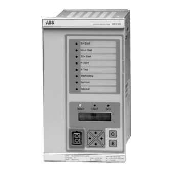
REX 521 1MRS 751107-MUM Protection Relay Operator’s Manual Instructions 3.1. HMI features • Push-buttons for navigating, [C] Clear/Cancel and [E] Enter • Language selection • Setting values are protected by passwords • Display backlight • Display contrast • Display test •... - Page 10 REX 521 Protection Relay 1MRS 751107-MUM Operator’s Manual REX 521 READY START TRIP Fig. 3.1.-1 HMI front view 1. Alarm LEDs 2. LED indicator: Trip, CBFP 3. LED indicator: Start, Block 4. LED indicator: Ready, IRF, Test mode 5. LCD 6.
-
Page 11: Push-Button Functions
REX 521 1MRS 751107-MUM Protection Relay Operator’s Manual 3.1.1. Push-button functions The HMI includes push-buttons for operating the protection relay. ↑ ↓ A quick touch on the arrow button up [ ] or down [ ] is interpreted as one step upwards or downwards in a menu or as the minimum step up or down in setting mode of a parameter. -
Page 12: Selecting Language
• clearing the disturbance recorder data 3.1.2. Selecting language MAIN MENU GROUP MENU SUBGROUP MENU PARAMETER MENU Configuration General Identification Analog scales Hardware = REX 521 Active language Software Communication = English Protection Digital Inputs Display General Control Cond. monit. Measurements... -
Page 13: Passwords
REX 521 1MRS 751107-MUM Protection Relay Operator’s Manual 3.1.3. Passwords Protection Control Cond. monit. Communication Comm. settings Comm. settings DNP 3.0 Rear port IEC 103 Measurements MODBUS SPA FRONT SPA address Power Quality = 001 SPA REAR Baud rate Configuration... -
Page 14: Display Test
REX 521 Protection Relay 1MRS 751107-MUM Operator’s Manual Increase Push Decrease Fig. 3.1.5.-1 Adjusting display contrast • The display contrast may be adjusted anywhere in the menu structure except in the setting menus where the [E] button is used for entering the setting mode. -
Page 15: Menu Chart
REX 521 1MRS 751107-MUM Protection Relay Operator’s Manual 3.2. Menu chart The contents of the menu chart depend on the configuration of the relay. However, the main menu structure is always preserved. MAIN MENU GROUP MENU SUBGROUP MENU PARAMETER MENU... -
Page 16: Measurement Menu
REX 521 Protection Relay 1MRS 751107-MUM Operator’s Manual 3.2.1. Measurement menu The contents of the measurement menu depend on the relay configuration. If a measurement view is selected, it remains active after the time-out period. The same is true with the manual control view. From other views, the display reverts to idle mode at the same time as the backlight is switched off. -
Page 17: Event Menu
REX 521 1MRS 751107-MUM Protection Relay Operator’s Manual Table 3.2.1-1 Measurement view (Continued) Function block Measurand View P (kW) Q (kVAr) Power E (kWh, kvarh) P-kW Q-kvar PF cos +0.00 P demand Q demand Energy kvarh Reverse energy kvarh These two parameters are shown in the... -
Page 18: Manual Control
REX 521 Protection Relay 1MRS 751107-MUM Operator’s Manual Measured values Events IL1-A 25.0 14 Stored 3I>> : TRIP 2002-22-01 L1 , L2 , L3 08:32:23.100 3I>> : START 2002-22-01 L1 , L2 , L3 08:32:23.100 Protection Protection 3I>> 3I>> Actual settings... -
Page 19: Controlling Breaker
REX 521 1MRS 751107-MUM Protection Relay Operator’s Manual 3.2.3.2. Controlling breaker The object control menu is in Control\Manual control\Control CB. Only the current position of the breaker is shown and no control is possible in remote or control off mode. In local mode the state of the breaker is shown and the possible →... - Page 20 REX 521 Protection Relay 1MRS 751107-MUM Operator’s Manual The current state of the interlocking of the object can prevent the select or execute requests. In that case the text =Interlocked is displayed for three seconds. The attempted operation is cancelled and after the three seconds the current state of the object is displayed.
-
Page 21: Setting Parameters
REX 521 1MRS 751107-MUM Protection Relay Operator’s Manual 3.2.4. Setting parameters The setting parameters are listed in the CD-ROM Technical Descriptions of Functions (see “Related documents” on page 6). ↑ ↓ → ← 1. Navigate to the right parameter using the buttons [... -
Page 22: Indication Messages
For information about the meaning of each event, refer to Event List for REX 521 on the CD-ROM (see “Related documents”... -
Page 23: Self-Supervision
REX 521 1MRS 751107-MUM Protection Relay Operator’s Manual 3I>: BLOCK Fig. 3.3.1.-2 Indication of blocking If a protection function trips, the name of the function and the text TRIP appear on the display. The red LED indicator is lit. The faulted phases are displayed in this case. -
Page 24: Condition Monitoring Indication
REX 521 Protection Relay 1MRS 751107-MUM Operator’s Manual 3.3.3. Condition monitoring indication If the relay configuration includes condition monitoring functions that are not directly related to any protection function or to the internal relay condition, indication messages with the message SUPERV and an explanatory text appear if faults are found. -
Page 25: Led Indicators
REX 521 1MRS 751107-MUM Protection Relay Operator’s Manual 3.4. LED indicators 3.4.1. Green indication LED (READY) Non-active LED: OFF Auxiliary supply voltage has been disconnected. Check that the auxiliary voltage is disconnected before taking any further action. Steady LED: READY Normal operation. -
Page 26: Alarm Leds
REX 521 Protection Relay 1MRS 751107-MUM Operator’s Manual Steady LED: TRIP A protection function has tripped and an indication message is displayed. The trip indication is latching, that is, it must be reset by pressing the button or via the serial communication. -
Page 27: Test Mode
REX 521 1MRS 751107-MUM Protection Relay Operator’s Manual Test mode Digital inputs, output relays and IRF relay may be tested by setting the parameter Test mode to Testing in the menu Main menu\Tests\General. When test mode is activated, the green READY indicator is blinking. For more... -
Page 28: Function Block Test
REX 521 Protection Relay 1MRS 751107-MUM Operator’s Manual 4.3. Function block test The outputs (Start and Trip) of a function block can be activated locally via the HMI or externally via serial communication. This is possible without setting the relay in test mode as described in “Test mode”... -
Page 29: Index
REX 521 1MRS 751107-MUM Protection Relay Operator’s Manual Index About this manual ..................5 Alarm LEDs ..................9, 26 1-8 ....................... 26 Modes ....................26 Bit masks ....................21 Altering contents ................21 Breaker ..................... 19 Buttons ...................... 11 Digital inputs Testing .................... - Page 30 HMI password ..................13 Serial communication password ............13 Primary values ..................14 Push-buttons ..................... 11 Arrow button ..................11 Functions .................... 11 Operating the relay ................11 Remote control ..................18 REX 521 protection relay features ............. 8 Selecting language ..................12...
- Page 31 REX 521 1MRS 751107-MUM Protection Relay Operator’s Manual Test Display ....................14 Function block ..................28 I/O ....................... 27 IRF ...................... 27 Test mode ....................27 Cancelling ................... 27 Timeout ..................... 19...
- Page 32 ABB Oy Distribution Automation P.O. Box 699 FI-65101 Vaasa FINLAND Tel. +358 10 22 11 Fax. +358 10 224 1094 www.abb.com/substationautomation...