Kenwood TKR-740 Service Manual
Vhf fm repeater
Hide thumbs
Also See for TKR-740:
- Service manual (102 pages) ,
- Brochure & specs (2 pages) ,
- Instruction manual (2 pages)
Table of Contents
Advertisement
VHF FM REPEATER
TKR-740
SERVICE MANUAL
E VERSION
GENERAL ................................................................ 2
SYSTEM SET-UP .................................................... 2
INSTALLATION ....................................................... 3
OPERATING FEATURES ........................................ 4
REALIGNM ENT ..................................................... 13
APPLICATION NOTE ............................................ 15
DISASSEM BLY FOR REPAIR ............................... 24
CIRCUIT DESCRIPTION ........................................ 26
SEM ICONDUCTOR DATA .................................... 43
COM PONENTS DESCRIPTION ............................ 46
PARTS LIST ........................................................... 48
EXPLODED VIEW .................................................. 61
PACKING ............................................................... 63
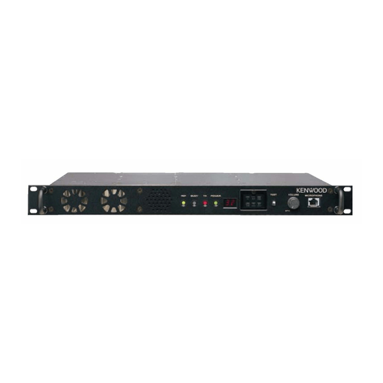
Panel (Front)
LED
(A62-0726-03)
(B30-2197-05)
LED
(B30-0864-05)
CONTENTS
TERM INAL FUNCTION ......................................... 64
ADJUSTM ENT ...................................................... 69
PC BOARD
SCHEM ATIC DIAGRAM ...................................... 109
BLOCK DIAGRAM ............................................... 121
LEVEL DIAGRAM ................................................ 123
INTERCONNECTION DIAGRAM ........................ 125
KES-4 (EXTERNAL SPEAKER) ........................... 127
KPG-46 (PROGRAM M ING INTERFACE CABLE) ..... 128
SPECIFICATIONS ............................... BACK COVER
©
2002-12 PRINTED IN JAPAN
B51-8642-00 (S) 272
PUSH KNOB (TEST)
(K29-3002-14)
LED ASSY
(LA301DB)
LED
KNOB (VOL)
(B30-2198-05)
(K29-4539-04)
CONTROL UNIT (X53-3882-71) ...................... 81
TX UNIT (X56-3072-70) ................................... 91
RX UNIT (X55-3050-11) ................................. 103
MODULAR JACK
(E08-0876-05)
Advertisement
Table of Contents

Related Manuals for Kenwood TKR-740


Summary of Contents for Kenwood TKR-740
-
Page 1: Table Of Contents
VHF FM REPEATER TKR-740 SERVICE MANUAL E VERSION © 2002-12 PRINTED IN JAPAN B51-8642-00 (S) 272 PUSH KNOB (TEST) Panel (Front) (K29-3002-14) (A62-0726-03) (B30-2197-05) LED ASSY MODULAR JACK (B30-0864-05) (LA301DB) (E08-0876-05) KNOB (VOL) (B30-2198-05) (K29-4539-04) CONTENTS GENERAL ..............2 TERM INAL FUNCTION ......... 64 SYSTEM SET-UP ............ -
Page 2: General
Choose the type Frequency range (MHz) RF power Type of transceiver 158-174 (RX)/146-174 (TX) 5W to 25W TKR-740 E External RX Filter RX modification See page 3 Repeater See page 14 programming & setup A personal computer (IBM PC compatible), programming cable (KPG-46), and programming disk (KPG-47D) are required for programming. -
Page 3: Installation
TKR-740 INSTALLATION RX M ODIFICATION FOR EXTERNAL PRESELECTOR FILTER This model may be modified to use an external pre-selector filter. 1 Remove the RX cover panel. 6 Replace the screws on the RX unit and shield case, and the 2 Remove the flat clip spring from IC4 and L16 flat clip spring on IC4 and L16. -
Page 4: Operating Features
TKR-740 OPERATING FEATURES 1. Front Panel q q q q q w w w w w e e e e e t t t t t r r r r r y y y y y u u u u u... - Page 5 TKR-740 OPERATING FEATURES 3. Tw o 7-segment LED Displays Channel display (1-32): while operating normally in User “E2” displayed when the channel data is not written. ● ● Mode “PC” displayed while in PC Mode. “E3” displayed when PLL is unlocked .
- Page 6 TKR-740 OPERATING FEATURES 4. Programmable Functions TKR-740 contains many Programmable Functions tabled below. Programmable Function Description Channel 1-32 Directly select Channel 1 to 32, respectively. Channel Down The channel decrements by one. Channel Up The channel increments by one. AUX Out 1-6 Off AUX Out 1 to 6 ports become deactivated, respectively.
- Page 7 Resets to default condition set up by FPU. None No function. The following Programmable Functions are output functions used to tell the condition of the TKR-740 to an external device. ● The output functions can be assigned to only AUX Outputs as follows.
- Page 8 TKR-740 OPERATING FEATURES 5. Trigger Assignment The Programmable Functions described above can be assigned LED in the PF Key turns on either conditions. ‘O’ expresses to PF Keys, AUX Input, and Start Up according to following that the trigger is available the Programmable Function. ‘X’...
- Page 9 TKR-740 OPERATING FEATURES Trigger Condition of LED on Function Monitor On Monitor On/Off Turns on in ON status Monitor Momentary Turns on in ON status CW ID On Turns on while transmitting CW Message 1-8 On Turns on while transmitting...
- Page 10 This mutes a receiving radio’ s speaker audio before its receiver circuit shuts off and causes squelch tail noise 8. Signalling Feature in the speaker audio. The TKR-740 can select the time between 8.1 Multiple QT/ DQT The TKR-740 can function as a multiple-QT/DQT decode/ 140 to 200 ms that the DQT turn-off code is sent.
- Page 11 Last Used, Selected + Talkback, Priority, Priority plus Talkback, and Selected. 12. Intercom Operation 1) Last Called : The TKR-740 reverts to the channel upon which The repeater has an Intercom feature which allows wireline a call was last received even if scanning has resumed (power communication between the dispatcher at the remote site and on default = selected channel).
- Page 12 QT/DQT received signal. 21. Start Up When the TKR-740 is first turned on or is reset, up to 3 functions pre-programmed into the Start Up function are 17. Take Over Take Over function is used to disable the remote wireline executed in sequence.
-
Page 13: Realignment
TKR-740 REALIGNMENT 1. M odes User Mode PC Mode PC Programming Mode PC Test Mode PC Tuning Mode Firmware Programming Mode M ode Function Use this mode for normal operation. User Mode Use this mode to make various settings by means of the FPU through the RS-232C port. - Page 14 4. Firmw are Programming M ode 3-1. Preface 4-1. Preface The TKR-740 uses flash memory to allow it to be easily The TKR-740 repeater is programmed by using a personal upgraded when new features are released in the future. computer, programming interface and KPG-47D software.
-
Page 15: Application Note
TKR-740 APPLICATION NOTE 1. External I/ O Connector Description 1.1. M ICROPHONE jack Connector Terminal Name Description No Connection Power Source; 13.2V / 0.75A maximum PTT (PC serial data from radio) PC Read/Write, PC Tuning, Firmware programming MIC Ground MIC input (600Ω) - Page 16 TKR-740 APPLICATION NOTE 1.3. CONTROL I/ O jack Connector Terminal Name Description I/ O Level No Connection RXD2 (PC serial data to radio) PC Read/Write, PC Tuning, Remote RS-232C Level TXD2 (PC serial data from radio) PC Read/Write, PC Tuning, Remote...
- Page 17 TKR-740 APPLICATION NOTE *3 TD ; TX Data input-transmit signalling (QT / DQT / LTR) *4 The output logic level of all AUX O terminals (Section 1.3, input. (Impedance 600Ω) 1.4), including any AUX I/O programmed as “AUX Output” TA ; TX Audio input-transmit audio input.
- Page 18 TKR-740 APPLICATION NOTE *4 AUX I/O 6 and 7 can each be modified to sink up 600mA Change R320 for AUX I/O 6 [R319 for AUX I/O 7] of open collector current. The following modification from 1kΩ (RK73GB1J102J) to 0Ω (R92-1252-05).
- Page 19 TKR-740 APPLICATION NOTE 1.5 Connection to External Equipment 1.5 Connection to External Equipment Terminal Remote Termination(VEGA) M odel 38-M AX (ZETRON) Raider (TRIDENT) RXD2 TXD2 AUXI 1 (F1 to F8 optionally) AUXI 2 (F1 to F8 optionally) AUXI 3 (F1 to F8 optionally)
- Page 20 External Equipment 2.1. LTR Logic Controllers 1) Program the RX/TX channel frequency but do not set QT/ 4) Connect the 25-pin D-sub on TKR-740 to the interface port DQT tone/codes.. on LTR controller with a cable. 2) Edit the channel data by pressing [F10].
- Page 21 2.2. Intercom Function The Intercom function allows two communications between operation. a dispatcher at a remote console and the TKR-740 unit at a <Edit>➔<Optional features>➔<AUX I/O Ports...>➔ site via the remote termination unit-to-console audio link. This <AUX Input Functions (12-pin & 25-pin)...>➔“TX function operates in repeater or base station mode.
- Page 22 TKR-740 APPLICATION NOTE 3.1. Internal I/ O Terminal Description Terminal Name Description I/ O Level Power Source 13.2V TX audio output to optional board 35mVrms @ 2.4kHz Deviation TX audio input from optional board RX audio output to optional board...
- Page 23 Use the SPM line on the 25 Pin D-sub. IC45, pin 2 (IC45 device: LA4422). The scrambler function is primarily designed for TKR-740 4. FPU Setting For Optional Board base station operation. However if used in repeater operation,...
-
Page 24: Disassem Bly For Repair
Fan enclosure Cooling fan CN104 Cable holder TX UNIT (A/3) CN104 (2) Attach the fan enclosure to the front of the TKR-740(E) heatsink so that the enclosure tabs are securely mounted Fan cable to the heatsink chassis. Chassis (Front side) - Page 25 TKR-740 DISASSEMBL Y FOR REPAIR How to install a coaxial cable betw een CN301 2. Cooling Fan (Rear side) (1) Attach the fan to the front of the chassis with the 2 supplied and CN1 (TX unit) screw s. When you connect CN1 (TX unit A/3) and CN301 (TX unit B/3) w ith a coaxial cable, you must guide and align the coaxial cable w ith the shielded case as show n in the figure below .
-
Page 26: Circuit Description
CIRCUIT DESCRIPTION 1.Outline 2.Transmitter Unit The TKR-740 is a VHF repeater operating in the158-174MHz The transmitter unit (X56-307 A/3) consists of the follow ing (RX), 146-174M Hz (TX) frequency range. It has the follow ing circuits: (1) internal/external reference circuit, (2) transmitter... - Page 27 TKR-740 CIRCUIT DESCRIPTION Fig.2 Transmitter reference PLL circuit 2.3 Transmitter DDS circuit The transmitter DDS circuit produces the reference frequency steps, such as 2.5kHz and 1.25kHz, can be used frequency signal (4.5 M Hz) for the transmitter main PLL and because the DDS output frequency is variable.
- Page 28 TKR-740 CIRCUIT DESCRIPTION 2.4 Transmitter main PLL circuit The transmitter main PLL circuit produces the transmitter the 100kHz comparison frequency. The phase difference signal frequency signal and consists of VCO (Q1 and Q2) and a single- is converted to a DC signal w ith a lag-lead type loop filter. The chip PLL IC (IC101).
- Page 29 TKR-740 CIRCUIT DESCRIPTION Fig.5 Driver circuit 2.6 M odulation level adjustment circuit The level adjustment circuit adjusts the modulation signal from the CPU using the FPU. IC105 is a modulation signal level to provide the required level of modulation and adjusts summing amplifier (A/2) and a signalling signal amplitude fine- the transmitter output pow er.
- Page 30 TKR-740 CIRCUIT DESCRIPTION 2.7 Other circuits In addit ion, IC106 is an EEPROM . The t ransm it t er adjustment data adjusted for each unit is w ritten into the EEPROM . If the unit is installed in another set, it is not necessary to adjust it again from the beginning, but only fine- adjustment is necessary for each unit.
- Page 31 3.6 Common mode spurious filter circuit The APC circuit consists of differential amplifier IC302 (B/ The TKR-740 has a filter L304 at the DC pow er line inlet in 2), DC amplifier Q301, and sw itching transistors Q304. The the final unit to reduce common mode radiation from the power pow er setting range in the high-pow er mode is 25 W;...
- Page 32 TKR-740 CIRCUIT DESCRIPTION 4.Receiver Unit The receiver unit (X55-305) consists of the following circuits: (1) front-end circuit, (2) narrow IF circuit, (3) w ide IF circuit, (4) receiver main PLL circuit, (5) receiver DDS circuit, (6) baseband circuit, and (7) other circuits.
- Page 33 TKR-740 CIRCUIT DESCRIPTION 4.2 Narrow IF circuit The narrow IF circuit consists of tw o-pole M CF XF2, four- enters V2 of the electronic volume control IC is adjusted, the pole M CF XF4, IF amplifier Q25, IF amplifier Q32, FM detector signal passes through the hysteresis circuit AF sw itch Q34, IC IC7,crystal oscillator X1 and ceramic filters CF1, CF3.
- Page 34 TKR-740 CIRCUIT DESCRIPTION 4.3 Wide IF circuit The w ide IF circuit consists of tw o-pole M CF XF1, four- The level of the signal that enters V1 of the electronic pole M CF XF3, IF amplifier Q24, IF amplifier Q31, FM detector volume control IC is adjusted, the signal passes through AF IC IC8, crystal oscillator X2, ceramic filter CF2, CF4.
- Page 35 TKR-740 CIRCUIT DESCRIPTION 4.4 Receiver main PLL circuit The receiver main PLL circuit consists of VCO (Q8, Q9) tw o bands: the Q8 VCO covers the low er band and the Q9 and a single-chip PLL IC IC1, buffer amplifier Q14, RF amplifier VCO covers the upper band.
- Page 36 TKR-740 CIRCUIT DESCRIPTION 4.5 Receiver DDS circuit 4.7 Other circuits The receiver DDS circuit varies the reference frequency of In addition, the receiver circuit contains an EEPROM (IC10) the receiver main PLL to implement fine frequency steps which as in the transmitter circuit. Adjustment data for each unit cannot be achieved by a single-loop PLL.
- Page 37 TKR-740 CIRCUIT DESCRIPTION 5.Control Circuit 5.1 M ain CPU The main CPU (IC17) is a 16-bit single-chip microcomputer The control unit (X53-388) consists of the follow ing circuits: containing a 128k ROM and a 5k RAM . This CPU controls the...
- Page 38 TKR-740 CIRCUIT DESCRIPTION 5.2 Sub CPU The sub CPU (IC18) is of the same type as the main CPU, but is programmed so that it operates as the sub CPU by connecting its pin 18 to GND (pin 18 of the main CPU is connected to Vdd.).
- Page 39 TKR-740 CIRCUIT DESCRIPTION 5.3 DSP circuit The DSP circuit filters transmitter/receiver audio signals amplified by IC22 (B/2), fed to pin 6 (Vin R) of codec IC27, and and decodes signalling (QT, DQT). This circuit consists of IC30, converted from analog to digital at a sampling frequency of IC24, IC27, IC22, IC31, IC34, and IC25.
- Page 40 TKR-740 CIRCUIT DESCRIPTION 5.4 AF PA circuit The AF PA circuit is an AF amplifier for driving speakers to pin test connector “ SPO, SPG” on the rear panel. The monitor received audio signals. This circuit consists of IC45. impedance of the internal speaker is adjusted to provide an The 4W audio output can be provided to an external 4 ohm audio output of about 0.2 W w hen the internal speaker installed...
- Page 41 TKR-740 CIRCUIT DESCRIPTION 5.6 Baseband circuit modulation input (RTA), and demodulation outputs include The baseband circuit sw itches betw een the modulation receive audio output (RA), receive data output (RD), and remote signal to the transmitter unit, demodulation signal from the receive audio (RRA).
- Page 42 TKR-740 CIRCUIT DESCRIPTION 5.7 M icrophone AGC circuit 5.9 Pow er supply circuit The microphone AGC circuit AGC-amplifies an audio signal The pow er supply circuit generates pow er to operate the coming from a local microphone so that it does not overdrive CPU, DSP, flash ROM , bi-directional buffer, and baseband the modulator.
-
Page 43: Semiconductor Data
TKR-740 SEMICONDUCTOR DATA MAIN CPU : 30622M4-103GP (CONTROL UNIT IC17) Pin No. Port name I/ O Function 63~70 A7~0 Flash memory/Sub CPU address bus ■ Pin function DSP IDM A w rite output Pin No. Port name I/ O Function... -
Page 44: Semiconductor Data
TKR-740 SEMICONDUCTOR DATA Pin No. Port name I/ O Function Pin No. Port name I/ O Function Take over control output Prog. I/O / Main CPU / TX / Rxcontrol,0:TX / 1:RX Local speaker output select IRQ2 Interrupt Req./pull up... - Page 45 TKR-740 SEMICONDUCTOR DATA POWER MODULE : RA30H1317M (TX UNIT IC301) ■ M AXIM UM RATINGS (Tc=25°C, Zg=ZI=50Ω) Symbol Parameter Conditions Ratings Unit SUPPLY VOLTAGE Vgg 5.0V, Zg=ZI=50Ω Vdd 12.5V, Pin=50mW, GATE BIAS VOLTAGE Zg=ZI=50Ω DRAIN CURRENT INPUT POWER f=135-175MHz, Vgg 5.0V 100 mW OUTPUT POWER f=135-175MHz, Vgg 5.0V...
-
Page 46: Components Description
TKR-740 COMPONENTS DESCRIPTION CONTROL UNIT (X53-3882-71) RX UNIT (X55-3050-11) REF.No Parts name DESCRIPTION PIN. No Parts name DESCRIPTION M ULTIPLEXER DOUBLE BALANCED M IXER IC3~6 FLASH ROM IC10 VOLTAGE DETECTOR SHIFT REGISTER IC12,13 AF AM P IC14 M ULTIPLEXER DC AM P... -
Page 47: Components Description
TKR-740 COMPONENTS DESCRIPTION TX UNIT (X56-3072-70) PIN. No Parts name DESCRIPTION PIN. No Parts name DESCRIPTION IC1,2 Q301 TRANSISTOR DC AM P D/A CONVERTER Q302,304 TRANSISTOR DC SWITCH SHIFT REGISTER Q308 TRANSISTOR DC SWITCH IC100 Q309 TRANSISTOR DC SWITCH IC101... -
Page 48: Parts List
Parts w ithout Parts No. are not supplied. Y: AAFES (Europe) X: Australia M: Other Areas Les articles non mentionnes dans le Parts No. ne sont pas fournis. Teile ohne Parts No. w erden nicht geliefert. TKR-740 (Y54-3142-71) CONTROL UNIT (X53-3882-71) Ref. No. Address Parts No. Description Destination Ref. - Page 49 TKR-740 PARTS LIST CONTROL UNIT (X53-3882-71) Ref. No. Address Parts No. Description Destination Ref. No. Address Parts No. Description Destination parts parts C 90 C K73G B1E 103K C HIP C 0.010UF K C 203 C K73G B1E 103K C HIP C 0.010UF K...
- Page 50 TKR-740 PARTS LIST CONTROL UNIT (X53-3882-71) Ref. No. Address Parts No. Description Destination Ref. No. Address Parts No. Description Destination parts parts J700 E 08-0876-05 MO DULAR JAC K R 107,108 R K73G B1J223J C HIP R 1/16W R 109...
- Page 51 TKR-740 PARTS LIST CONTROL UNIT (X53-3882-71) Ref. No. Address Parts No. Description Destination Ref. No. Address Parts No. Description Destination parts parts R 200 R K73G B1J471J C HIP R 1/16W R 307 R K73G B1J473J C HIP R 1/16W...
- Page 52 TKR-740 PARTS LIST CONTROL UNIT (X53-3882-71) RX UNIT (X55-3050-11) Ref. No. Address Parts No. Description Destination Ref. No. Address Parts No. Description Destination parts parts IC 5 NJM78L08UA BI-P O LAR IC C 16 C C 73G C H1H150J C HIP C...
- Page 53 TKR-740 PARTS LIST RX UNIT (X55-3050-11) Ref. No. Address Parts No. Description Destination Ref. No. Address Parts No. Description Destination parts parts C 94,95 C C 73G C H1H040C C HIP C 4.0P F C 169,170 C 92-0628-05 C HIP -TAN...
- Page 54 TKR-740 PARTS LIST RX UNIT (X55-3050-11) Ref. No. Address Parts No. Description Destination Ref. No. Address Parts No. Description Destination parts parts L79-1734-05 HE LIC AL BLO C K R 25 R K73F B2A100J C HIP R 1/10W L17,18 L40-1005-34...
- Page 55 TKR-740 PARTS LIST RX UNIT (X55-3050-11) Ref. No. Address Parts No. Description Destination Ref. No. Address Parts No. Description Destination parts parts R 99 R K73G B1J152J C HIP R 1.5K 1/16W R 170 R K73G B1J104J C HIP R...
- Page 56 TKR-740 PARTS LIST RX UNIT (X55-3050-11) TX UNIT (X56-3072-70) Ref. No. Address Parts No. Description Destination Ref. No. Address Parts No. Description Destination parts parts Q 20 2SB1386(R ) TR ANSISTO R C 56 C C 73G C H1H471J C HIP C...
- Page 57 TKR-740 PARTS LIST TX UNIT (X56-3072-70) Ref. No. Address Parts No. Description Destination Ref. No. Address Parts No. Description Destination parts parts C 171,172 C K73G B1H102K C HIP C 1000P F K C 278-281 C K73G B1H102K C HIP C...
- Page 58 TKR-740 PARTS LIST TX UNIT (X56-3072-70) Ref. No. Address Parts No. Description Destination Ref. No. Address Parts No. Description Destination parts parts C N301 E 04-0408-05 R F C O AXIAL R E C E P TAC LE (SMB) R 19...
- Page 59 TKR-740 PARTS LIST TX UNIT (X56-3072-70) Ref. No. Address Parts No. Description Destination Ref. No. Address Parts No. Description Destination parts parts R 107 R K73G B1J471J C HIP R 1/16W R 222 R K73G B1J103J C HIP R 1/16W...
- Page 60 TKR-740 PARTS LIST TX UNIT (X56-3072-70) Ref. No. Address Parts No. Description Destination Ref. No. Address Parts No. Description Destination parts parts R 355 R K73G B1J473J C HIP R 1/16W Q 13 2SC 3356 TR ANSISTO R R 357...
-
Page 61: Exploded View
TKR-740 TKR-740 EXPLODED VIEW Ax10 EXCITER Ax11 Ax10 FINAL CONTROL Ax14 Ex12 Hx10 X56 (B/3) IC301 50x2 Hx10 X56 (A/3) X53 (A/4) X56 (C/3) Ex11 X53 (B/4) X53 (D/4) A M3x5 :N32-3005-45 B M4x8 :N32-4008-45 C M3x6 :N35-3006-46 D M3x6... -
Page 62: Packing
TKR-740 PACKING 49. DRESSED SCREW (N08-0543-04) 6. INSTRUCTION MANUAL (B62-1700-00) 22. FUSE (BLADE) (10A) (F06-1032-05) 41. PROTECTION BAG (H25-0029-04) 21. SQUARE PLUG 2. FRONT GLASS (E59-0410-05) (B10-2590-04) 9. LEAD WIRE WITH CONNECTOR (E31-3228-05) 46. HANDLE 42. PROTECTION BAG (K01-0421-05) (H25-0720-04) 39. -
Page 63: Terminal Function
TKR-740 TERMINAL FUNCTION CONTROL UNIT (X53-3882-71) Terminal Terminal Terminal Terminal Terminal function I/ O Terminal function I/ O name name Local speaker input RX Audio (filtered signal) Local speaker ground RX Audio ground AF volume control output Detector audio AF volume control input... -
Page 64: Control Unit (X53-3882-71)
TKR-740 TERMINAL FUNCTION CONTROL UNIT (X53-3882-71) Terminal Terminal Terminal Terminal Terminal function I/ O Terminal function I/ O name name Speaker mute signal Remote RX signal (voice) AUX06 Auxiliary output 6 Remote TX signal (voice) RX signal ground RPTT Remote Press-to-talk sw itch... - Page 65 TKR-740 TERMINAL FUNCTION CONTROL UNIT (X53-3882-71) CN706 CN702 Terminal Terminal Terminal Terminal Terminal function I/ O Terminal function I/ O name name No connection Local speaker input Local speaker ground Sw itch S700 signal AF volume control output No connection...
-
Page 66: Tx Unit (X56-3072-70)
TKR-740 TERMINAL FUNCTION TX UNIT (X56-3072-70) CN102 Terminal Terminal Terminal Terminal Terminal function I/ O Terminal function I/ O name name REF OUT RX reference signal output (coaxial) DRIV OUT Drive signal output (coaxial) CN103 Terminal Terminal Terminal Terminal Terminal function... - Page 67 TKR-740 TERMINAL FUNCTION TX UNIT (X56-3072-70) CN307 Terminal Terminal Terminal Terminal Terminal function I/ O Terminal function I/ O name name RX Audio (filtered signal) Pow er supply ground RX Audio ground CN308 Detector audio Detector audio ground Terminal Terminal...
- Page 68 TKR-740 ADJUSTMENT Test Equipment Required for Alignment No. Test Equipment M ajor Specifications 1. Standard Signal Generator Frequency Range 136 to 174M Hz. (SSG) M odulation Frequency modulation and external modulation. Output 0.1µV to greater than 1mV. 2. Pow er M eter Input Impedance 50Ω.
- Page 69 TKR-740 ADJUSTMENT Adjustment Location • Top view RA RD TA TD DC 13.2V REMT TEST TX OUT EXT REF IN CONTROL /SPKR RX IN FUSE CN102 MICROPHONE VOLUME Section Arrangement (Top view ) FINAL UNIT TX UNIT CONTROL RX UNIT...
- Page 70 TKR-740 ADJUSTMENT ✱ Factory use CH1 to CH16 Beat Pow er W/ N NOTE Frequency Frequency Shift H/ L 158.1000 136.0000 Wide A Low VCO A Low 162.1000 145.5000 Wide A Center VCO A Center 165.9000 154.9500 Wide A High VCO A High 166.1000...
-
Page 71: Rx Unit (X55-3050-11)
TKR-740 ADJUSTMENT RX UNIT M easurement Adjustment Specifications/ Item Condition Test Unit Terminal Unit Parts M ethod Remarks equipment 1. Setting 1) VOL : OFF 2) 13.2V External pow er supply 3) POWER : ON 2. RX Lock 1) CH6 (RX B Hi) TC2 4.5V ADJ... - Page 72 TKR-740 ADJUSTMENT RX UNIT M easurement Adjustment Specifications/ Item Condition Test Unit Terminal Unit Parts M ethod Remarks equipment 7. Analog 1) Connect the SSG to RX IN, then select the RX IN PC ADJ Squelch channel that the user w ill use (Wide)
- Page 73 TKR-740 ADJUSTMENT RX UNIT M easurement Adjustment Specifications/ Item Condition Test Unit Terminal Unit Parts M ethod Remarks equipment 11.RA Output 1) Connect the SSG to RX IN, then select the RX IN PC ADJ Level channel that the user w ill use (Wide)
- Page 74 TKR-740 ADJUSTMENT TX UNIT M easurement Adjustment Specifications/ Item Condition Test Unit Terminal Unit Parts M ethod Remarks equipment 17.TX M easure the pow er level at TX OUT. Pow er TX OUT PC ADJ ± 0.5W Pow er 1) CH1 (Low ) meter 25.0W...
- Page 75 TKR-740 ADJUSTMENT TX UNIT M easurement Adjustment Specifications/ Item Condition Test Unit Terminal Unit Parts M ethod Remarks equipment 21.DQT 1) CH2 (VCO-A Center) M OD ANA TX OUT PC ADJ Balance 2) CH5 (VCO-B Center) Oscilloscope A/3 CONTROL I/O...
- Page 76 TKR-740 ADJUSTMENT TX UNIT M easurement Adjustment Specifications/ Item Condition Test Unit Terminal Unit Parts M ethod Remarks equipment 24.TA Dev 1) CH2 (VCO-A Center) M OD ANA TX OUT Check 2.4kHz± 0.1kHz Check 2) CH5 (VCO-B Center) Oscilloscope A/3 CONTROL I/O (Wide) AG.f : 1kHz...
- Page 77 TKR-740 ADJUSTMENT TX UNIT M easurement Adjustment Specifications/ Item Condition Test Unit Terminal Unit Parts M ethod Remarks equipment 28.QT Dev 1) CH2 (VCO-A Center) M OD ANA TX OUT Check 0.60kHz±0.05kHz Check 2) CH5 (VCO-B Center) Oscilloscope A/3 (Wide) QT : 151.4Hz...
- Page 78 TKR-740 ADJUSTMENT TX UNIT M easurement Adjustment Specifications/ Item Condition Test Unit Terminal Unit Parts M ethod Remarks equipment 33.Repeat 1) CH4 (Center Frequency) M OD ANA TX OUT PC ADJ Gain Level M OD : 1kHz Oscilloscope A/3 1kHz ±...
- Page 79 TKR-740 ADJUSTMENT BPF-w ave Example : The w ave w ill look like this w hen using a frquency of 166.000 M Hz. (Factory default setting: 166.000M Hz) M CF-w ave (Wide) (Narrow )
- Page 80 TKR-740 PC BOARD CONTROL UNIT (X53-3882-71) (A/ 4) Component Side View (J72-0668-11) CONTROL UNIT (X53-3882-71) (A/4) X53-3882-71 A/4 R306 R305 C303 J72-0668-11 R155 C313 R304 C302 R303 C301 R302 C300 RSSI C147 C207 C210 C166 R124 R123 R329 C125 C160...
- Page 81 TKR-740 PC BOARD CONTROL UNIT (X53-3882-71) (A/4) CONTROL UNIT (X53-3882-71) (A/ 4) Foil Side View (J72-0668-11) X53-3882-71 A/4 J72-0668-11 R307 R125 R164 C154 C184 C212 R165 C107 IC38 R166 C213 C161 IC15 C162 C206 C106 C158 R168 C209 C203 C208...
- Page 82 TKR-740 PC BOARD CONTROL UNIT CONTROL UNIT (X53-3882-71) (A/ 4) Component Side + Foil Side View (J72-0668-11) (X53-3882-71) (A/4) TA7805F TC74VHC245FT X53-3882-71 A/4 R306 R305 C303 J72-0668-11 R307 R155 C313 R304 C302 R303 C301 R302 C300 RSSI R125 C147 C154...
- Page 83 TKR-740 PC BOARD CONTROL UNIT (X53-3882-71) (B/ 4) CONTROL UNIT (X53-3882-71) (B/ 4) CONTROL UNIT (X53-3882-71) (B/ 4) Component Side View (J72-0668-11) Foil Side View (J72-0668-11) Component Side + Foil Side View (J72-0668-11) CONTROL UNIT CONTROL UNIT CONTROL UNIT (X53-3882-71) (B/4)
- Page 84 TKR-740 PC BOARD CONTROL UNIT (X53-3882-71) (C/ 4) Component Side View (J72-0668-11) CONTROL UNIT (X53-3882-71) (D/ 4) Component Side View (J72-0668-11) CONTROL UNIT X53-3882-71 D/4 X53-3882-71 C/4 (X53-3882-71) (D/4) J72-0668-11 J72-0668-11 CN705 R716 C714 R718 MDAT VR700 C716 C750 VR701...
- Page 85 TKR-740 PC BOARD TX UNIT (X56-3072-70) (A/ 3) Component Side View (J72-0879-09) R182 R222 R149 IC203 Q208 SUB PLL R183 X56-3072-70 (A/3) MAIN PLL D206 J72-0879-09 R270 C219 L247 D202 IC103 C220 R123 L209 L204 L202 R205 DRIV C104 CN103...
- Page 86 TKR-740 PC BOARD TX UNIT (X56-3072-70) (A/ 3) Foil Side View (J72-0879-09) IC108 C124 C125 C237 IC205 R251 C291 L243 R185 C290 R257 C254 R269 R258 Q207 C232 Q110 C287 R211 R221 Q114 C296 C147 R241 Q113 R44 R43 C216...
- Page 87 TKR-740 BU4094BCFV TA7808S AT24C08N10SI18 M62364FP TA75S01F AD9835BRU CD8468 PC BOARD TX UNIT (X56-3072-70) (A/ 3) Component Side + Foil Side View (J72-0879-09) IC108 C124 I G O R182 C125 R222 R149 IC203 O G I Q208 SUB PLL R183 X56-3072-70 (A/3)
- Page 88 TKR-740 PC BOARD TX UNIT (X56-3072-70) (B/ 3) (C/ 3) Component Side View (J72-0879-09) CN302 C431 DRIV R303 R358 R359 C432 CN301 R304 C324 C325 L308 C420 R325 Q309 R324 R306 R320 R308 CN306 C329 D320 C303 CN307 D304 Q301...
- Page 89 TKR-740 PC BOARD TX UNIT (X56-3072-70) (B/3) (C/3) Foil Side View (J72-0879-09) C326 C302 C305 C304 C332 R330 X56-3072-70 (C/3) J72-0879-09 CN502 D500 C414 TX UNIT (X56-3072-70) (C/3) C315 X56-3072-70 (B/3) J72-0879-09 C316 Component side Layer 1 Layer 2 Layer 3...
- Page 90 TKR-740 PC BOARD TX UNIT (X56-3072-70) (B/3) (C/3) Component Side + Foil Side View (J72-0879-09) CN302 C431 DRIV R303 R358 R359 CN301 C432 R304 C326 C324 C302 C325 L308 C420 C305 R325 Q309 C304 R324 C332 R306 R320 R308 CN306...
- Page 91 TKR-740 PC BOARD RX UNIT (X55-3050-11) Component Side View (J72-0666-01) RX UNIT R107 (X55-3050-11) C123 C124 C127 R120 R103 R109 C129 R121 R114 R193 R111 IC13 IC14 R118 C142 C138 C217 R115 O G I C203 R126 C150 C108 R163...
- Page 92 AT24C08N10SI18 TA31137FN CD8468 RX UNIT (X55-3050-11) Foil Side View (J72-0666-01) RX UNIT (X55-3050-11) C126 C133 C134 R151 R169 R175 R176 C228 R196 C147 C160 R166 R168 C213 C112 R159 C111 C169 R146 R177 C162 X55-3050-11 R105 R130 R180 R167 R136 C132 R188 J72-0666-01...
- Page 93 TKR-740 NJM78L05UA BU4094BCFV TA7808S AT24C08N10SI18 PC BOARD RX UNIT (X55-3050-11) M62364FP AD9835BRU TA31137FN Component Side + Foil Side View (J72-0666-01) RX UNIT R107 (X55-3050-11) C123 C124 R120 C127 R103 CD8468 C129 R109 R121 R114 R193 R111 C126 IC13 IC14 R118...
-
Page 94: Schematic Diagram
TKR-740 SCHEMATIC DIAGRAM Note : The components marked w ith a dot ( ) are parts of layer1. ●... - Page 95 TKR-740 SCHEMATIC DIAGRAM Note : The components marked w ith a dot ( ) are parts of layer1. ●...
- Page 96 TKR-740 SCHEMATIC DIAGRAM Note : The components marked w ith a dot ( ) are parts of layer1. ●...
-
Page 97: Block Diagram
TKR-740 TKR-740 BLOCK DIAGRAM... -
Page 98: Level Diagram
TKR-740 TKR-740 LEVEL DIAGRAM Note Because the speech output terminal reaches 12dB SINAD w hen receiving high frequencies, you need an • antenna input level (60% modulation) Even though the speech output terminal reaches 4W w hen receiving low frequencies, you need a 1kHz AF •... -
Page 99: Interconnection Diagram
TKR-740 TKR-740 INTERCONNECTION DIAGRAM... -
Page 100: External Speaker)
TKR-740 TKR-740 KES-4 (EXTERNAL SPEAKER) KPG-46 (PROGRAMMING INTERFACE CABLE) KPG-46 External view KES-4 Jumper lead Connector Speaker cable Black lead 15 12 Crimp terminal (E23-0613-05) Black/White lead When using an external speaker : 3. When not using the external speaker, replace the jumper 1. - Page 101 MEMO...
-
Page 102: Specifications
Band Spread ..............28M Hz EXT Reference Sensitivity (10M Hz, 50Ω) ......–10dBm KENWOOD follow s a policy of continuous advancement in development. For this reason specifications may be changed w ithout notice. KENWOOD CORPORATION 2967-3, Ishikaw a-machi, Hachioji-shi, Tokyo 192-8525, Japan KENWOOD U.S.A.