Panasonic HL-C2 Series User Manual
Ultra high-speed, high-accuracy
laser displacement sensor
Hide thumbs
Also See for HL-C2 Series:
- User manual (98 pages) ,
- User manual (100 pages) ,
- User manual (24 pages)

Related Manuals for Panasonic HL-C2 Series


Summary of Contents for Panasonic HL-C2 Series
- Page 1 Ultra High-Speed, High-Accuracy Laser Displacement Sensor HL-C2 Series User's Manual ME-HLC2-16 2017.5 panasonic.net/id/pidsx/global...
- Page 2 Thank you for purchasing Ultra High-Speed, High-Accuracy Laser Displacement Sensor “HL-C2 Series”. To fully use this product safely and properly, please read this manual carefully. Please check our website ( http://panasonic.net/id/pidsx/global ) about new info of the product and new version of the user’s manual. ■ Note 1.
-
Page 3: Whole User's Manual Construction
Preface Whole USER’S MANUAL Construction The HL-C2 Series is prepared for the following user’s manuals. Read them as necessary. The application software “Adobe Reader” is required for viewing the files. ® The latest application (Adobe Reader 11.0 as of May, 2013) can be freely downloaded from the following URL. -
Page 4: Monitor Aim
User's Manual This manual describes installation method, operation Intelligent Monitor AiM method, functional details and error messages of the software. It also describes an evaluation analysis of HL-C2 Series or use of buffering function and received light intensity ME-HLCSAIM-08 2013.6 panasonic.net/id/pidsx/global waveform display function, which are useful for optimum system setting. -
Page 5: Manual Construction
Preface Manual Construction This chapter provides cautions for safe and correct Preface operation of the product. Be sure to read this chapter. This chapter explains the configuration, installation, and connection of the system Prior to Use (Controller, Sensor head, and Intelligent monitor AiM). -
Page 6: Table Of Contents
Preface Contents Whole USER’S MANUAL Construction 1 Export Regulations by Japanese ■ USER’S MANUAL for Intelligent Government ··············································· 28 Monitor AiM ·························································· 2 ■ Compliance with Export Regulations Manual Construction ··································· 3 by Japanese Government ···························· 28 Contents ·························································· 4 ■... - Page 7 Preface 2 I/O Terminal Block ······················· 2-1 ■ Refractive Index ·········································· 4-29 ■ Zero Set ························································ 4-31 2-1 Functions and Arrangements of I/O ■ Timing····························································· 4-33 Terminal Block ·············································· 2-2 ■ Reset ······························································ 4-34 ■ Hold ································································ 4-35 2-2 I/O Circuit ··········································· 2-4 ■...
- Page 8 Preface 4-4 Supplemental Explanation ············· 4-84 8 Specifications ································ 8-1 4-4-1 Alarm Setting and Outputs ············ 4-84 8-1 Controller Specifications ··············· 8-2 4-4-2 Conditions When Output Data become 8-2 Sensor Head Specifications ········· 8-8 Unfixed ························································ 4-85 4-4-3 Memory Save and Terminal Setting ·· 4-88 ■...
-
Page 9: Safety Precautions
Preface Safety Precautions This product is intended to detect the objects and does not have the control function to ensure safety such as accident prevention. Do not use the product as a sensing device to protect human body. Please use the products that comply with local laws and standards for human body protection specified by e.g., OSHA, ANSI and IEC. -
Page 10: Correct Handling
Preface Correct Handling Note the following points when installing and using HL-C2 Series. Installation Environment ■ Do not install the product in the following conditions. • Where the ambient temperature, ambient humidity or ambient illuminance of beam receiving surface is beyond the range of specifications Refer to “Use Environment”.) -
Page 11: Power Supply Voltage
Preface Ambient humidity Use the sensor within a range of 35 to 85% RH. Avoid using it in places that may be exposed to dew condensation due to rapid temperature change. Ambient illuminance of light receiving surface Use the sensor in locations where illuminance from incandescent lamps is 3,000 lx or less. -
Page 12: Warming Up Time
Preface Warming Up Time Allow at least 30 minutes of warming up after turning on the power to ensure the performance of the product. Measures to Noise • Install the product as far away as possible from noise source such as high-voltage lines, high-voltage device, power lines, power device, machines which generate a large starting and stopping surge, welding machines and inverter motor. -
Page 13: Power Supply
Preface Power Supply ■ Power Supply • Select a power supply with a ripple 0.5V or less (P-P) and a current capacity 2A or more. • When using a commercial switching regulator, be sure to ground the frame ground (F.G.) terminal to avoid the influence of high frequency noise. •... -
Page 14: Grounding
Preface Grounding ■ Ground the device when noise influence is large • Under normal use, the product has sufficient noise resistance. In an environment with particularly high noise levels, however, ground it securely. ■ Use an exclusive ground • Use wires of 1.5 mm or more and establish a class D ground with a ground resistance of 100Ω... -
Page 15: Precautions For Positive Ground
Preface Precautions for positive ground environment The GND terminals of 24VDC (-) and USB port, SG of RS-232C, and COMMON terminal (-) of the input / output circuit are connected inside the HL-C2. The FG terminal, USB port connector shell, RS-232C connector shell and Ethernet connector shell are also connected inside the HL-C2. -
Page 16: Installation
Preface Installation ■ Controller ・ Install the controller unit according to “1-3 Installation Method”, assuring plenty of space around it. If it is installed in a manner other than specified, failures may occur due to temperature rise. ・ If the controller is mounted internally on the place where air circulation is blocked such as in a control board, the ambient temperature will rise due to heat generated by the controller. -
Page 17: Cautions On Handling Laser Light
Use the interlock control input terminal when using as an emergency stop circuit for safety. Release the short circuit by short bar to stop laser emission. 4) Please contact Panasonic Industrial Devices SUNX if the system breaks down. Laser radiation is not automatically stopped during disassembling the sensor head. -
Page 18: Warning Label
Preface ■ Warning Label ● 10mm type (HL-C201A) In Japanese / English / Korean In Chinese (E type only) <Label position> ● 30mm type (HL-C203B) In Japanese / English / Korean In Chinese (E type only) <Label position>... - Page 19 Preface ● 5mm type (HL-C205B) In Japanese / English / Korean In Chinese (E type only) <Label position> ● 50mm type (HL-C205C) In Japanese / English / Korean In Chinese (E type only) <Label position>...
- Page 20 Preface ● 85mm type (HL-C208B) In Japanese / English / Korean In Chinese (E type only) <Label position> ● 85mm type (HL-C208C) In Japanese / English / Korean In Chinese (E type only) <Label position>...
- Page 21 Preface ● 110mm type (HL-C211B) In Japanese / English / Korean In Chinese (E type only) <Label position> ● 110mm type (HL-C211C) In Japanese / English / Korean In Chinese (E type only) <Label position>...
- Page 22 Preface ● 350mm type (HL-C235BE) In Japanese / English / Korean In Chinese <Label position> ● 350mm type (HL-C235CE) In Japanese / English / Korean In Chinese <Label position>...
- Page 23 Preface ● 350mm type (HL-C235CE-W) In Japanese / English / Korean In Chinese <Label position> ● 8mm type (HL-C201A□-SP2□) In Japanese / English / Korean In Chinese (E type only) ● 15mm type (HL-C201A□-SP3□) In Japanese / English / Korean In Chinese (E type only) <Label position>...
-
Page 24: Ce Compliant Condition
70mm or less 【Contact for CE】 <Until June 30, 2013> Panasonic Industrial Devices Sales Central Europe AG Rudolf-Diesel-Ring 2, D-83607 Holzkirchen, Germany <From July 1, 2013> Panasonic Marketing Europe GmbH Panasonic Testing Center Winsbergring 15, 22525 Hamburg, Germany... -
Page 25: Fda
Preface ■ Export to US When the laser product mounted on equipment is exported to the United States, they are subjected to the regulation of the Food and Drug Administration. In order to prevent the injury on users due to laser products from happening, FDA has established PART 1040 (Performance Standards for Light-Emitting Products). -
Page 26: Labeling
Preface ■ Labeling The product uses the following labels in accordance with FDA standards. ● Aperture/Warning label, Protective housing label ● Certification/Identification label <Label position> The figures above show the examples of major model (for L-C203F(E)/ HL-C203F(E)-MK). As for label positions of other models, refer to the Instruction Manual for sensor head included in each product. -
Page 27: Beam Attenuator
Preface ■ Beam Attenuator Use the attached beam attenuator if there is a danger of getting laser beam into your eyes during operation. Beam attenuator Beam attenuator Fix the beam attenuator with When the beam attenuator is the attached screws to cover not used, fix it to either side the light emitting surface. -
Page 28: Fda Standard
Preface ■ FDA Standard Class Requirements IIIa IIIb Performance (all laser products) Protective housing [1040.10(f)(1)] *3,4 *3,4 *3,4 *3,4 *3,4 *3,4 Safety interlock [1040.10(f)(2)] Location of controls [1040.10(f)(7)] Viewing optics [1040.10(f)(8)] Scanning safeguard [1040.10(f)(9)] Performance (laser system) Remote interlock connector [1040.10(f)(3)] Key control [1040.10(f)(4)] Emission indicator [1040.10(f)(5)]... -
Page 29: Remote Interlock
Preface Class is based on the maximum level of laser exposure during operation. Required wherever and whenever such human access to laser radiation levels that exceed the limits of Class I is not necessary for the product to perform its intended function. Required at the protective housing which is designed to be removed or displaced during operation or maintenance, if removal or displacement of the protective housing could permit human access to laser or... -
Page 30: Government
Preface Export Regulations by Japanese Government ■ Compliance with Export Regulations by Japanese Government Some models are subject to export control, which is defined by “Foreign Exchange and Foreign Trade Act”. ● Export controlled products Below products fall under the export control, which is defined by “Foreign Exchange and Foreign Trade Act”. -
Page 31: Product
Preface ■ Specification of Export Uncontrolled Product The specification of display resolution and measurement resolution for the export uncontrolled products are shown below. Other specifications not mentioned here are the same as export controlled products. 0.25µm Resolution The programmable display and Intelligent Monitor AiM displays the measured value in increments of 0.25µm. - Page 32 Preface MEMO...
- Page 33 Prior to Use This chapter explains the configuration, installation method, and connection method of the system (Controller, Sensor Head, Compact Programmable Display, and Intelligent Monitor AiM). 1-1 System Configuration ··················· 1-2 1-1-1 System Configuration ······················· 1-2 1-1-2 System Components & Accessories List ·· 1-3 1-2 Part Names and Functions ·············...
-
Page 34: Prior To Use
Chapter 1 Prior to Use 1-1 System Configuration 1-1-1 System Configuration The system configuration and the cables for connecting the devices are shown as below. PLC etc. Ethernet cable Controller USB cable (2m) Compact programmable display Connecting cable(3m) PLC etc. RS-232C cable Extension cable for sensor head Sensor head B... -
Page 35: List
*1: HL-C2C□ is attached. *1: HL-C2C□ is attached. HL-C2 series setup CD-ROM In this setup CD-ROM, PDF data of “HL-C2 Series USER’S MANUAL” , “HL-C2 Series USER’S MANUAL (RS-232C Communication Control)”, “HL-C2 Series USER’S MANUAL (USB Communication Control)” and “HL-C2 Series USER’S MANUAL (Ethernet Communication Control)”, the USB driver. -
Page 36: Sensor Head Accessories
Chapter 1 Prior to Use ■ Sensor Head Accessories The accessories of the sensor head are as shown below. Main unit of Warning label sensor head In Japanese / English / Korean In Chinese (E type only) Instruction manual of sensor head ■... -
Page 37: Extension Cable For Sensor Head
(Type:HL-C2CCJ10) (Type:HL-C2CCJ20) (Type:HL-C2CCJ30) ■ Compact programmable display (Optional) Refer to the "HL-C2 Series User's Manual: Programmable Display" for handling regarding installation and connection. Refer to "Chapter 3 Programmable Display Operation" for the operation method. Main unit of compact programmable display Compact programmable display brackets &... -
Page 38: Connection Cable For Compact Programmable Display (3M) (Optional)
Chapter 1 Prior to Use ■ Connection cable for compact programmable display (3m) (Optional) (Type: HL-C2GT-C3) ■ Intelligent Monitor AiM Intelligent Monitor AiM and “HL-C2 Series USER’S MANUAL: Intelligent Monitor AiM” downloaded Internet website (http://panasonic.net/id/pidsx/global). ■ Ethernet Communication Setting Tool Ethernet Tool Configurator WD (compatible to Ver.1.62 and later) can be... -
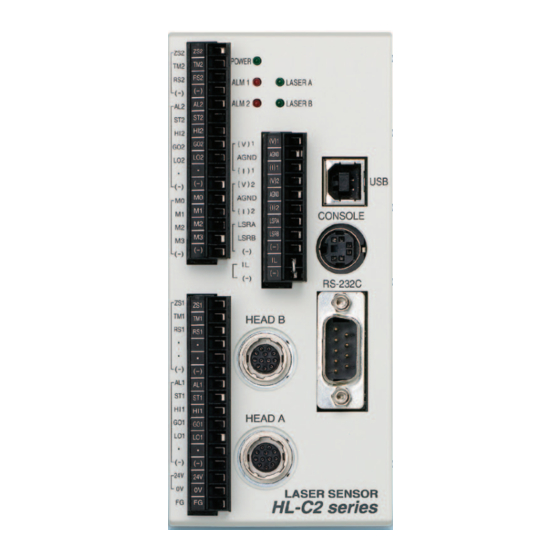
Page 39: Part Names And Functions
Chapter 1 Prior to Use 1-2 Part Names and Functions 1-2-1 Controller ●HL-C2C□ ●HL-C21C□ 1 2 3 4 1 2 3 4 1. POWER Indicator Lights up in green when electricity is provided to the controller. 2. ALM1 (Alarm) Indicator Abnormal condition indicator for OUT1. - Page 40 Chapter 1 Prior to Use 6. Analog Output Terminal Terminal for analog data output. 7. Laser Control Terminal Stops laser emission in case of short-circuiting. 8. Remote Interlock Terminal Stops laser emission when its opened. 9. USB Connector Used for communication with PC using USB. 10.
-
Page 41: Sensor Head
Chapter 1 Prior to Use 1-2-2 Sensor Head (1) Laser Emission Indicator (LASER ON) Lights up in green during laser emission. (2) Measurement Range Indicator (RANGE) Lights up in yellow when the target reaches at approximately center of the measurement. Blinks in yellow when the target enters within the measurement range. -
Page 42: Installation Method
Chapter 1 Prior to Use 1-3 Installation Method Before installing each device, read carefully the explanation of the setting environment, concerning about noise or radiation, and the power supply. “Correct Handling”. Refer to 1-3-1 Controller The controller can be installed by using DIN rail or using screws. ■... -
Page 43: Sensor Head
Chapter 1 Prior to Use 1-3-2 Sensor Head Securely fix the sensor head in two screw holes using M5 screws. •The tightening torque should be 1.2N·m or less. •The depth of both screw holes is 10mm, not through-holes. Be careful to choose screws with considering its length. - Page 44 Chapter 1 Prior to Use • Measurement of a rotating target When measuring a rotating target, the direction of the sensor head should be as shown below to minimize the effect of vertical oscillation or displacement. • Measurement of step detection When measuring a moving target that has difference grooves, the direction of the sensor head should be as shown below to minimize interference caused by target edges.
- Page 45 Chapter 1 Prior to Use ● Measurement of a black target or low-light intensity When measuring a low-reflectance black target, light intensity reflected from the target decreases and the signal from the linear image sensor is also getting smaller. As a result, it decreases the resolution.
-
Page 46: Mounting Nd Filter
Chapter 1 Prior to Use ● Angle between the measurement center and the sensor head Diffuse reflection line Diffuse reflection surface Mount the sensor head as shown at the right, so the emitter surface and receiver surface of sensor head is parallel to a measuring target. For the measurement center distance and “8-2 Sensor measurement range, refer to... -
Page 47: Connection
Chapter 1 Prior to Use 1-4 Connection 1-4-1 Connection Method of Power Supply Connect 24VDC power supply wiring with “24V” and “0V” terminals of the terminal 3. ♦ Use twisted wires to minimize the effect of noise. ♦ Rated Voltage 24VDC Tolerance Voltage 24VDC... - Page 48 Chapter 1 Prior to Use Strip insulation from the end of the wire. Insert the wire in the terminal block until it contacts the back, then, secure it by tightening the screw. If two or more terminals are connected, twist wires before inserting them.
-
Page 49: Connection Of Intelligent Monitor Aim
A USB driver must be installed to a PC before connecting a controller and PC installed Intelligent Monitor AiM. For installation of the USB driver, refer to the “HL-C2 Series Intelligent Monitor AiM USER’S MANUAL”. The below operating environment is required for operating the intelligent monitor AiM. - Page 50 Chapter 1 Prior to Use MEMO 1-18...
-
Page 51: I/O Terminal Block ·······················
I/O Terminal Block This chapter explains I/O terminal blocks on the controller. 2-1 Functions and Arrangements of I/O Terminal Block ··························· 2-2 2-2 I/O Circuit ································· 2-4 2-3 Interlock Circuit ·························· 2-6 2-4 Analog Output Circuit ·················· 2-7 2-5 Timing Chart ····························· 2-8... -
Page 52: Functions And Arrangements Of I/O Terminal Block
Chapter 2 I/O Terminal Block 2-1 Functions and Arrangements of I/O Terminal Block Analog output terminal block/Laser control terminal block Terminal Function (V)1 Analog voltage output (for OUT1) AGND Analog ground (I)1 Analog current output (for OUT1) (V)2 Analog voltage output (for OUT2) AGND Analog ground (I)2... - Page 53 Chapter 2 I/O Terminal Block I/O terminal block Terminal Function Zero set input (for OUT2) ON during short circuit Timing input (for OUT2) ON during short circuit Reset input (for OUT2) ON during short circuit Common (-) Alarm output (for OUT2) Strobe output (for OUT2) Judgment HI output (for OUT2) Judgment GO output (for OUT2)
-
Page 54: I/O Circuit
Chapter 2 I/O Terminal Block 2-2 I/O Circuit ■ NPN Type The common (-) and the power supply (0V) for main unit are internally connected. Be sure not to cause the potential difference at operation. -
Page 55: Pnp Type
Chapter 2 I/O Terminal Block ■ PNP Type The common (-) and the power supply (0V) for main unit are internally connected. Be sure not to cause the potential difference at operation. -
Page 56: Interlock Circuit
Chapter 2 I/O Terminal Block 2-3 Interlock Circuit ■ NPN Type Connect IL and Common (-) in case of NPN output type. ■ PNP Type Connect IL+ and IL- in case of PNP output type. IL+ is connected to the 24V power supply at the internal circuit. Do not connect the voltage input or PNP transistor open collector output to it. -
Page 57: Analog Output Circuit
Chapter 2 I/O Terminal Block 2-4 Analog Output Circuit *: Either “1” or “2” is entered. · Do not short-circuit analog output terminals or apply voltage to them. · Use shielded wires for analog outputs. -
Page 58: Timing Chart
Chapter 2 I/O Terminal Block 2-5 Timing Chart • Normal measurement • Peak/bottom measurement The above chart uses peak measurement for explanation. • Peak to peak measurement... - Page 59 Chapter 2 I/O Terminal Block • Zero set by timing input during HOLD status is valid. • Reset input by timing input during HOLD status causes data unfixed status. The system holds this status until the timing input is cancelled. •...
- Page 60 Chapter 2 I/O Terminal Block ● Laser control Laser control input 100 to 120ms 100 to 120ms Emission Laser Stop Normal Normal Measurement status Data unfixed measurement measurement ● Interlock control Short circuit Remote interlock input Open 100 to 120ms Approx.
- Page 61 3-3 Screen Transition Diagram ················· 3-10 3-3-1 Display Waveform of Received Light Intensity ··············································· 3-14 3-3-2 Received Light Intensity at Peak ··············· 3-14 The screen data and "HL-C2 Series User's Manual: Programmable Display" can be downloaded from our Internet website (http://panasonic.net/id/pidsx/global).
-
Page 62: Programmable Display Operation
Chapter 3 Programmable Display Operation Operation Screens ■ Screens ● Top menu and Setting menu Top menu The left figure shows the Top screen. All kinds of screens displayed on the programmable display can be changed through any of the keys on the Top menu. -
Page 63: Shift Screen Levels
Chapter 3 Programmable Display Operation ■ Shift Screen Levels The operation screen consists of hierarchical tree structure. Touch the keys to move to the desired screen and set the required items. Touch the keys to shift the screen among the same hierarchical level. Same level Shift up/down one level Shift up/down one level... -
Page 64: Enter Value
Chapter 3 Programmable Display Operation ■ Enter Value Setting value This section explains how to enter the numerical value for upper/lower limit value or offset. A numerical keypad is displayed on Decimal point Enter the screen for numerical input. Touch the frame above the setting value. The cursor blinks and numerical value can be entered. - Page 65 Chapter 3 Programmable Display Operation MEMO...
-
Page 66: Basic Operation
Chapter 3 Programmable Display Operation Basic Operation 3-2-1 First Measurement This section explains the basic operating procedures of measurement with HL-C2 Series product. Initial power-on STEP1 Connect the controller, sensor head and compact programmable display. “1-1 System Configuration” Check connection Make sure that the +24VDC power supply is connected correctly. -
Page 67: Save Settings
Chapter 3 Programmable Display Operation Position adjustment of sensor head STEP3 Check the mounting direction of sensor head. Select the optimum direction according to the shape or moving direction of measurement object. Note that a different installation method is used between Check installation specular reflection and diffuse reflection measurement. - Page 68 Chapter 3 Programmable Display Operation Thickness measurement STEP6 This step explains the basic setting procedures of thickness measurement. The example below shows the procedures for thickness measurement using two sensor heads. Adjust to measurement center Adjust to measurement center Set the installation mode to “Diffuse Reflection” and the measurement mode to “Diffuse Reflection [Standard]”.
- Page 69 Chapter 3 Programmable Display Operation Thickness measurement: glass material STEP7 1st Surface Near 1st Surface – Glass 2nd Surface Clearance (space) 2nd Surface Glass Set the installation mode to Specular Reflection and Measurement Basic Setting Mode to Specular Reflection [Standard]. Refer to STEP2 “Basic Setting”.
-
Page 70: Screen Transition Diagram
Chapter 3 Programmable Display Operation Screen Transition Diagram ■ Screen Flow Measurement Value Menu Whole waveform Received Light Intensity at Peak OUT1 (OUT2) Display Enlarged waveform screen OUT1 (OUT2) Operation Memory Change OUT1 & 2 Display Digit Number Update Cycle 3-10... - Page 71 Chapter 3 Programmable Display Operation Setting Menu Refer to Page 3-12. Head A The setting items of Head B are the same as Head A. Head B Refer to Page 3-12. OUT1 The setting items of OUT2 are the same as OUT1.
- Page 72 Chapter 3 Programmable Display Operation Head A (Head B) Menu 1/2 Head A (Head B) Menu 2/2 OUT1 (OUT2) Menu 1/2 Installation Mode Peak Recognition Sensitivity Output Selection Emission Adjustment Area –a Emission Adjustment Analysis Mode Emission Adjustment Area –b Emitted Light Intensity Search Filter Operation Alarm Delay Times...
- Page 73 Chapter 3 Programmable Display Operation System Menu 1/2 Common Menu OUT1 (OUT2) Menu 2/2 Copy Output Setting Sampling Cycle Analog Output at Alarm Terminal Input Control Priority Setting of Memory Change Analog Output at Data Unfixed Chattering Prevention for Memory Copy Digital Output at Alarm Terminal Input Initialization...
-
Page 74: Received Light Intensity At Peak
Chapter 3 Programmable Display Operation 3-3-1 Display Waveform of Received Light Intensity The compact programmable display can display the signal of received light intensity at Sensor Head A and B. When the measurement object is transparent, adjust the position while viewing the waveform to make the measurement easier. -
Page 75: Explanation Of Functions
Explanation of Functions This chapter describes various functions of the system. 4-1 Data Flow ································· 4-2 4-2 Classification of Function·············· 4-3 4-3 Function List & Initial Values ········· 4-3 4-3-1 Head Setting ····························· 4-7 4-3-2 OUT Setting ···························· 4-23 4-3-3 Common Setting ·······················... -
Page 76: Data Flow
Chapter 4 Explanation of Functions 4-1 Data Flow Up to two sensor heads can be connected to the controller. Individual measurement by each of sensor head and calculation of measurement values for two sensor heads can be performed. Operation flow of each function is shown as below. -
Page 77: Classification Of Function
Chapter 4 Explanation of Functions 4-2 Classification of Function In this system, all functions are classified into four categories for fixing stable measurement and various outputs. Classification Details Function setting for stable measurement by improving accuracy of laser Head Setting emission intensity Function setting related to output data processing OUT Setting... - Page 78 Chapter 4 Explanation of Functions Memory Ref. Function Details Initial value change*1 page Measurement Upper measurement limit value A (positive number) Correct Upper measurement limit Corrects the measurement value a (positive number) value to the measurement 4-19 Calibration object’s color, material, Measurement...
- Page 79 Chapter 4 Explanation of Functions Memory Ref. Function Details Initial value change*1 Page Analog Output Sets the analog output status at Hold previous Alarm alarm operation. value 4-48 Fixes the analog output status Fixed Value +10.800[V] at alarm operation. Analog Output at Sets the analog output status at ...
- Page 80 Chapter 4 Explanation of Functions Memo Ref. Function Details Initial value chang page Makes the settings of the measurement data output RS-232C Output for RS-232C communication. RS-232C Output Sets the output mode of the Handshake 4-70 Mode measurement data. Sets output type...
-
Page 81: Head Setting
Chapter 4 Explanation of Functions 4-3-1 Head Setting ■ Installation Mode Measurement type can be selected from the diffuse reflection and specular reflection according to the kind of measurement object. Diffuse Reflection Specular Reflection Select Setting for measuring any objects other than Setting for measuring mirror-surface mirror-surface or transparent objects and transparent objects. -
Page 82: Measurement Mode
Chapter 4 Explanation of Functions ■ Measurement Mode The optimum digital processing type can be selected to measurement object types. The measurement mode is a function for selecting the optimum measurement algorithm such as unbalance correction of received light waveform. Select the optimum measurement mode depending on the material of target or application purpose to get the stable measurement value. - Page 83 Chapter 4 Explanation of Functions ● How to use Display the “Measurement Mode” screen. Setting screen of sensor head A Setting screen of sensor head B Touch the appropriate measurement mode key to a target object.
-
Page 84: Emission Adjustment
Chapter 4 Explanation of Functions ■ Emission Adjustment This function sets an appropriate emitted light intensity to a measurement object. AUTO is set as a default. “AUTO” automatically sets optimum emitted light intensity to meet the reflection light amount of the measurement target. When the function is set to “AUTO”, the current light intensity is displayed in percent figures. -
Page 85: Emission Adjustment Area
Chapter 4 Explanation of Functions ■ Emission Adjustment Area This function specifies an emission auto adjustment area. The light intensity feedback function operates between the two cells from starting cell to ending cell. In case of measuring a transparent object where the high reflectance in the surrounding affects the emission, it is possible to adjust the emission on the beam receiving surface you wish to detect by specifying an emission adjustment area. - Page 86 Chapter 4 Explanation of Functions Head A ( or Area B ) in order to input the values. Touch Touch the number keys to specify the area. Touch key to decide on the specified area. 4-12...
-
Page 87: Emitted Light Intensity Search
Chapter 4 Explanation of Functions ■ Emitted Light Intensity Search This function searches the received light intensity of a measurement surface and sets the appropriate emitted light intensity automatically. Set this function when measuring the thickness of a transparent object with low received light. -
Page 88: Alarm Delay Times
Chapter 4 Explanation of Functions ■ Alarm Delay Times This function holds the previous (latest) normal value up to the setting number of times when an alarm is issued. This function relates to the digital measurement value, analog output, alarm terminal output, controller alarm indicator under an alarm status. -
Page 89: Measurement Surface Reference
Chapter 4 Explanation of Functions ■ Measurement Surface Reference This function selects the counting reference of the setting surface at “Output Selection”. Before measuring a transparent object, select the measurement surface reference from “Near Setting” (counting the layer of the measurement surface which is set at “Output Selection”... -
Page 90: Measuring Range
Chapter 4 Explanation of Functions ■ Measuring Range A given range can be specified for measurement. When you want to measure thickness, etc. of a transparent object, operation in “Output selection” becomes impossible if there are seven or more measurement faces. Measurement becomes possible by specifying a face to be detected in measuring range specification. - Page 91 Chapter 4 Explanation of Functions ● How to use Display the “Measuring Range” screen. Setting screen for Sensor Head B Setting screen for Sensor Head A Switch between “Measuring Point a” and “Measuring Point b” by touching the keys. Touch ) and enter the setting value.
-
Page 92: Laser Control
Chapter 4 Explanation of Functions ■ Laser Control This function switches ON/OFF of the laser emission. With this function, laser emission, that is unnecessary except at measurement, can be stopped. · While the laser emission stop is input (with LSRA and LSRB short-circuited) from the laser control terminal of the controller, the setting there influences this function. -
Page 93: Calibration
Chapter 4 Explanation of Functions ■ Calibration This function corrects the deviation of the measurement value caused from the color, material, or surface condition of the measurement object. As shown below, the value can be corrected by setting two points of “a” and “b”... - Page 94 Chapter 4 Explanation of Functions Set/change the measurement value or correction value. For setting or changing method of the measurement value and correction value, refer to “For inputting the measurement value or correction value” and “For loading the measurement value from the current value”. Touch the Excute key.
-
Page 95: Peak Recognition Sensitivity
Chapter 4 Explanation of Functions ■Peak Recognition Sensitivity This function sets the peak of the received light waveform and the peak recognition level. This function is effective when you cannot acquire the measurement value properly due to waveform instability. Detection error Setting value for peak... -
Page 96: Median Filter
Chapter 4 Explanation of Functions ■Median Filter Cut off changes in measurement values in order to prevent variation in measurement. The setting of median filter can be selected from “OFF”, “7 points”, “15 points” and “31 points”. Median filter is effective to cut off sudden changes in measurement values. Measurement session Measurement... -
Page 97: Out Setting
Chapter 4 Explanation of Functions 4-3-2 OUT Setting ■ Output Selection This function selects the output pattern of measurement values. The below list shows the setting items and the output details. Setting item Function Outputs the measurement value of the sensor head A. Outputs the measurement value of the sensor head B. - Page 98 Chapter 4 Explanation of Functions ● How to use Display the “Output Selection” screen. Selection screen of OUT1 Selection screen of OUT2 Touch the key (1) to change the list display. The list display is changed each time the key is touched.
-
Page 99: Transparent Object
Chapter 4 Explanation of Functions ■ Transparent Object This function selects a measurement surface from several surfaces in a transparent object. According to the setting of “measurement surface reference”, select a measurement surface in a transparent object. Single or several surfaces can be selected from 1st to the maximum surface. - Page 100 Chapter 4 Explanation of Functions ● How to use Display the “Output Selection” screen. Selection screen of OUT1 Selection screen of OUT2 Touch the key to select your setting of “Output Selection”. “■ Output Selection” Touch the key to change the screen for selecting the measurement surface of “Transparent Object”.
-
Page 101: Refractive Index Calculation
Chapter 4 Explanation of Functions ■ Refractive Index Calculation This function reflects the setting refractive index to the measurement result. When the “Refractive Index Calculation” function is set to “ON” for measuring a transparent object, the setting refractive index becomes effective and it is reflected in the measurement result. - Page 102 Chapter 4 Explanation of Functions Touch the key to change the setting and select the key of your choice. ”■ Output Selection” Touch the key to change the screen for selecting a measurement surface of “Transparent Object”. *The setting of the transparent object is valid only when “Transparent Object”...
-
Page 103: Refractive Index
Chapter 4 Explanation of Functions ■ Refractive Index This function is used for setting the refractive index of a transparent object to be measured. Sets the refractive index of the measurement object. The setting range is 0.500000 to 2.000000. “1.000000” is set as a default. ·... - Page 104 Chapter 4 Explanation of Functions Touch the “Refractive Index Calculation” key to change the setting to Touch the key to change the screen for setting “Refractive Index”. OUT1 OUT2 Touch ) key to input the setting value. Set the refractive index by the numeric keys. The setting range is 0.500000 to 2.000000.
-
Page 105: Zero Set
Chapter 4 Explanation of Functions ■ Zero Set This function is used for forcibly setting the measurement value to “0”. Normally, the amount of displacement is displayed in reference to the center of measurement of the sensor head. However, after this function is set to “ON”, the amount of displacement is displayed in reference to the position when the function is set to “ON”. - Page 106 Chapter 4 Explanation of Functions Touch the key to set the Zero Set measurement value to “0”. Zero set “OFF” Zero set “ON” Touch the Zero Set key again to return to the measurement reference position to the center of measurement (default) by zero set function.
-
Page 107: Timing
Chapter 4 Explanation of Functions ■ Timing The measurement value can be on hold at the desired timing. The measurement value is on hold by the timing terminal (TM1, TM2) of the external terminal input or by pressing the timing input button of compact programmable display. -
Page 108: Reset
Chapter 4 Explanation of Functions ■ Reset This function resets the measurement value. The measurement value can be reset by touching the “Reset” button. When executing the “Peak measurement”, “Bottom measurement”, or “Peak to Peak measurement”, the measurement value that has been on hold can be reset at the desired timing. -
Page 109: Hold
Chapter 4 Explanation of Functions ■ Hold This function stops the updating of the measurement value display. The updating of the measurement value display is stopped by touching the Hold button on the compact programmable display. This is a function only available for compact programmable display. -
Page 110: Analysis Mode
Chapter 4 Explanation of Functions ■ Analysis Mode This function performs the setting of the analysis mode. The below shows the function of each analysis mode. Setting item Function Outputs the displacement in the center of Normal measurement at a real time. Holds and outputs the maximum value of Peak the measurement value. -
Page 111: Filter Operation
Chapter 4 Explanation of Functions ■ Filter Operation This function cuts the unnecessary signal element to stabilize the measurement data. The filter operation is selectable from the moving average, low-pass filter, and high-pass filter. The filter picks out the measurement data for required amount of frequency, cuts the unnecessary signal element, then, acquires the stabilized measurement value. - Page 112 Chapter 4 Explanation of Functions · Make sure to perform the actual measurement and confirm the results before setting the cutoff frequency because of the different conditions. ● How to use Display the “Filter Operation” screen. Selection screen of OUT1 Selection screen of OUT2 Touch the “Filter Selection”...
-
Page 113: Operation Coefficient
Chapter 4 Explanation of Functions ■Operation Coefficient This function is used for multiplying the measurement value by the operation coefficient and outputting the data. Final measurement value = Operation coefficient x Measurement value + Offset value Outp Final meas. value Measurement value Meas. -
Page 114: Offset
Chapter 4 Explanation of Functions ■ Offset The desired setting value can be added to/subtracted from the measurement value. Set the offset value by measuring the size of a master (reference) measurement object. When measuring an object, set the Zero Set “ON” so that the judgment of the size tolerance can be performed easily because of the combination of the zero set and judgment output functions. - Page 115 Chapter 4 Explanation of Functions ■ Upper/Lower Limit Value of Judgment Output This function sets the upper and lower limit values for judgment of the measurement value. The output status changes in three types as the below: measurement value > upper limit value: HI Output lower limit value ≤...
- Page 116 Chapter 4 Explanation of Functions Touch the keys to change the screen between “Up Lmt Val” and “Lo Lmt Val”. OUT1 OUT2 Touch the ) key to prepare for inputting the setting value. Set the setting value by touching the numeric keys.
- Page 117 Chapter 4 Explanation of Functions ■ Upper/Lower Hysteresis of Judgment Output This function stabilizes the judgment output against the chattering of the measurement value. The below example graphically shows the correlation between the hysteresis value and ON/OFF of the output. The function acts on the upper/lower limit values when the output is in “ON”...
- Page 118 Chapter 4 Explanation of Functions Set the setting value by touching the numeric keys. The input range is +000.000000 to +950.000000[mm]. Touch the key to confirm the offset value. 4-44...
-
Page 119: Output
Chapter 4 Explanation of Functions ■ Analog Scaling This function executes scaling of the analog voltage output to a desired value. The system performs scaling of the analog voltage output to the desired value within ±10V. Fix two points of the desired voltages to “a” and “b” for each A and B of the current voltage. - Page 120 Chapter 4 Explanation of Functions Change the screen by each key. Screen Meas A Measurement value A input screen Volt a Voltage value a input screen For inputting the measurement Meas B Measurement value B input screen value or voltage value Volt b Voltage value b input screen For loading the measurement...
- Page 121 Chapter 4 Explanation of Functions For loading the measurement value from the current value Touch the key you want to load the value. Load Touch the key of the measurement value A or B. The screen is changed. Touch the key.
-
Page 122: Analog Output At Alarm
Chapter 4 Explanation of Functions ■ Analog Output at Alarm This function sets the analog output status when an alarm is issued. It can select whether holding the previous value or setting a fixed value for the analog output under an alarm operation status (poor light intensity, or measurement disabled when a target object goes off the measurement range). -
Page 123: Analog Output At Data Unfixed
Chapter 4 Explanation of Functions ■ Analog Output at Data Unfixed This function sets the analog output when the data is unfixed. “-999.999999” is displayed for the measurement value of the digital output at data unfixed and AiM. · The output range is -10.800 to +10.800[V], and the initial value is -10.800[V]. ·... -
Page 124: Digital Output At Alarm
Chapter 4 Explanation of Functions ■ Digital Output at Alarm This function sets the digital output status when an alarm is issued. It can select whether holding the previous value or setting a fixed value for the digital output (measurement value display of compact programmable display and the judgment output Intelligent Monitor AiM) under an alarm operation status (poor light intensity, or measurement disabled when the target object goes off the measurement range). -
Page 125: Alarm Output Delay
Chapter 4 Explanation of Functions ■ Alarm Output Delay This function delays the output from the alarm terminal. It can select whether outputting at a real time or holding the previous normal value up to the setting number of times under an alarm operation status (poor light intensity, or measurement disabled due to deviation from the range). -
Page 126: Digit Number Of Measurement Value
Chapter 4 Explanation of Functions ■ Digit Number of Measurement Value This function sets the display digit number of the measurement value. It can set the display of the number of decimal places on compact programmable display. The display of the number of decimal places can be selected among six settings: 6digits/5digits/4digits/3digits/2digits/1digit. -
Page 127: Common Setting
Chapter 4 Explanation of Functions 4-3-3 Common Setting ■ Sampling Period This function sets the sampling cycle of measurement. When measuring an object with poor received light intensity such as black rubber, extend the sampling cycle to get sufficient light for performing stable measurement. - Page 128 Chapter 4 Explanation of Functions ● How to use Display the “Sampling Cycle” screen. Touch the keys of Sampling Cycle to change the setting. The sampling cycle display is changed as below by touching the key. Also, it is changed in counterclockwise by touching the key.
-
Page 129: Terminal Input Control
Chapter 4 Explanation of Functions ■ Terminal Input Control Using this function, two outputs (OUT1 & OUT2) can be controlled by one input operation. Two outputs (OUT1 & OUT2) can be operated by inputting only OUT1 (the timing input, zero set input, and reset input). Select “All”... -
Page 130: Chattering Prevention Of Terminal Input
Chapter 4 Explanation of Functions ■ Chattering Prevention of Terminal Input This function can prevent the chattering of the terminal input. This function is used to prevent chattering for terminal input using the relay contact or switch contact. The below list shows three settings of the function. Setting Function OFF Continuous input of longer than 50µs... -
Page 131: Judgment Output Off Delay
Chapter 4 Explanation of Functions ■Judgment Output Off Delay This function is used for delaying the timing of switching OFF from ON of judgment output. 測 This function is effective for loading quickly fluctuated output into a sequencer, etc. Setting Function Output corresponding with a sampling cycle Off delay for 2ms... -
Page 132: Interference Prevention
Chapter 4 Explanation of Functions ■Interference Prevention This function is used for preventing interference between 2 sensor heads. Set this function when beam from the other sensor head enters into the mutual interference area. “8-6 Characteristics” – “Mutual Interference Area” When connecting two sensor heads, there is the case that one sensor head receives beam from the other sensor head, and this might cause a measurement error if the setting distance between the two sensor heads is... -
Page 133: System Setting
Chapter 4 Explanation of Functions 4-3-4 System Setting ■ Display Update Cycle of Measurement Value This function sets the display update cycle of the measurement value on the compact programmable display. Set the display update cycle to slower (longer) as possible because fast (short) display update cycle causes the measurement value display hard-to-read due to quickly change in the measurement value. -
Page 134: Value
Chapter 4 Explanation of Functions Setting at “Measurement Value” menu Display “Update Cycle of Meas Val” screen. Touch the “Update Cycle of Meas Val” key to select the setting. The display is changed as below each time the key is touched. Standard Slow Very Slow... -
Page 135: Change Indication Unit
Chapter 4 Explanation of Functions ■Change Indication Unit This function is used for changing the indication unit of the measurement value on compact programmable display. The indication unit of the measurement value is selectable from mm unit and µm unit. ・... -
Page 136: Output Setting Copy
Chapter 4 Explanation of Functions ■Output Setting Copy “OUT Setting” contents can be copied between OUT1 and OUT2. The setting contents related to the memory output that is specified at “Memory Change” function can be copied between OUT1 and OUT2 (OUT1→OUT2, OUT2→OUT1). -
Page 137: Priority Setting Of Memory Change
Chapter 4 Explanation of Functions ■ Priority Setting of Memory Change This function sets priorities among command or terminal memory changes. In case that the command is received a higher priority for memory change, memory change by the terminal is ignored (set the priority to “Terminal” before performing memory change from the terminal). -
Page 138: Memory Change
Chapter 4 Explanation of Functions ■ Memory Change This function specifies the destination (memory) for storing the setting contents. When starting up the system with the specified memory No. (other than the default setting), set the priority to command or terminal as below. “Priority Setting of Function operation at start-up Memory Change”... -
Page 139: Memory Copy
Chapter 4 Explanation of Functions ■ Memory Copy The stored contents in the memory can be copied to the other memories. If the destination and source memory is the same, the data in the memory is just overwritten. · Note that the copied setting contents are deleted at the next start-up if the copied setting content are not saved. -
Page 140: Initialization
Chapter 4 Explanation of Functions ■ Initialization This function deletes all setting contents in the memory and initializes the settings again. If the initialization is not saved, the system operates with the previous settings at the next start-up. Setting Function Initialize Initializes the settings other than the common memory settings. - Page 141 Chapter 4 Explanation of Functions In case of initializing the settings of all memories Display the “Initialize” screen. Touch the Initialize All Memory key. The confirmation message appears. Touch the key. The message of notifying the completion of initialization appears. *Touch the key to cancel the initialization and return to step 1.
-
Page 142: Save
Chapter 4 Explanation of Functions ■ Save This function saves the setting contents in all memories. Be sure to “save” the setting change before turning off the system. Failure to do deletes all setting change when the system is turned off. When re-starting up the system, the last setting contents (saved at last) appear. -
Page 143: Communication: Com Port
Chapter 4 Explanation of Functions ■ Communication: COM Port This function specifies the baud rate, the data length, and parity for RS-232C communication. These settings are used for communication with PC using RS-232C connector. Make sure to save the changed setting values, and then restart the power supply of the controller to validate the settings. -
Page 144: Rs-232C Output
Chapter 4 Explanation of Functions ■RS-232C Output This function is used for performance setting of the measurement data output from RS-232C to an external device. ● RS-232C Output mode RS-232C output is selectable from three modes. The initial value is set to “Handshake”. Setting item Contents In response to a request command from an upper device,... - Page 145 Chapter 4 Explanation of Functions ● How to use Display “RS-232C Output” screen. For RS-232C output mode: Touch the “Output mode” key to select the output mode. The display is changed as below each time the key is touched. Continuous Handshake Timing For RS-232C output type:...
-
Page 146: Console Setting
Chapter 4 Explanation of Functions ■ Console Setting This function sets “Panel Lock” and “Start-up Screen” of compact programmable display. Panel Lock “Panel Lock” is used for prohibiting the setting change on the compact programmable display to prevent any setting error occurrence due to unintentional operation on the compact programmable display. - Page 147 Chapter 4 Explanation of Functions OUT1 Display Displays the measurement value of OUT1. OUT1 Operate Sets the measurement value of OUT1, output (alarm, strobe, judgment output), and status of the hold, timing, zero set, and reset input. OUT2 Display Displays the measurement value of OUT2. OUT2 Operate Sets the measurement value of OUT2, output (alarm, strobe, judgment output), and status of the...
- Page 148 Chapter 4 Explanation of Functions Head A Menu Displays the Head A Menu screen. Head B Menu Displays the Head B Menu screen. OUT1 Menu Displays the OUT1 Menu1/2 screen. OUT2 Menu Displays the OUT2 Menu1/2 screen. Common Menu Displays the Common Menu screen. System Menu Displays the System Menu1/2 screen.
-
Page 149: Buffering Setting
Microsoft Excel application. For buffering by RS-232C communication, refer to “HL-C2 Series USER’S MANUAL RS-232C Communication Control” – “Chapter 5 Buffering Command”. For buffering by USB communication, refer to “HL-C2 Series USER’S... -
Page 150: Data Buffering Operation
Chapter 4 Explanation of Functions ■ Data Buffering Operation Data buffering procedure HL-C2 (host device) Perform necessary setting for buffering. · Buffering mode (1) Send · Buffering type Settings · Buffering rate · Accumulation amount · Sample trigger accumulation amount ·... -
Page 151: Buffering Operation
Chapter 4 Explanation of Functions ■ Buffering Operation This function accumulates the data during buffering operation. Set necessary parameters in advance and start buffering operation. · The starting of the buffering operation requires the buffering type and the accumulation amount to be set within the setting range. ·... - Page 152 Chapter 4 Explanation of Functions Timing Mode ・ When buffering operation starts, the timing input is turned to stand-by status. ・ Changing the timing input from “ON” to “OFF” during stand-by status starts data accumulation to the controller memory. ・ Timing input stops when the accumulation amount has reached the setting value or when buffering operation stops.
-
Page 153: Buffering Type
Chapter 4 Explanation of Functions ■ Buffering Type This function selects individual data accumulation or simultaneous data accumulation on OUT1 and OUT2. OUT1 is set as a default. The maximum accumulation data amount differs depending on buffering type. ■ Buffering Rate The buffering rate can be set for accumulating the measurement data for a long-duration by taking an adequate interval to the sampling cycle. -
Page 154: Trigger Conditions
Chapter 4 Explanation of Functions ■ Trigger Conditions This function is used for setting the trigger generation conditions when the buffering mode is set to trigger mode or sample trigger mode. The trigger conditions are selectable from “At timing input ON”, the results of “judgment output”... -
Page 155: Trigger Delay
Chapter 4 Explanation of Functions ■ Trigger Delay This function is used for delaying the timing of trigger detection when the buffering mode is set to trigger mode or sample trigger mode. Sets number of sampling times as the trigger delay value. Setting range is 0 to 100000000. -
Page 156: Status Readout
Chapter 4 Explanation of Functions ■ Status Readout This function checks the status of the measurement data accumulation. Use this function for checking the accumulation status before reading the accumulated data. After having checked the status, the controller replies one of the next status. -
Page 157: Data Read
Chapter 4 Explanation of Functions ■ Data Read The accumulated measurement data in the controller memory can be read out. The below shows two reading methods. Read method Contents Normal read Simply reads the accumulated measurement data as is. Reads the accumulated data by the difference from the previous data. -
Page 158: Supplemental Explanation
Chapter 4 Explanation of Functions Supplemental Explanation This section provides supplemental explanation for enhancing understandings of the system functions. 4-4-1 Alarm Setting and Outputs “Alarm status” means the measurement disabled status due to poor light intensity or out of measurement range. Sensor head A OUT1 Alarm output... -
Page 159: Unfixed ························································
Chapter 4 Explanation of Functions 4-4-2 Conditions When Output Data become Unfixed At immediately after change of “head Setting” or “OUT Setting”, or when the reset or laser emission stop is input, the operation status becomes “Data unfixed status” (data is not determined). - Page 160 Chapter 4 Explanation of Functions Alarm Code In case an alarm occurs, check the alarm code of alarm output read by RS-232C or USB communication. Alarm Name Description code Normal Normal measurement status. Measurement is not possible due to insufficient light intensity, or when the measurement surface specified by the transparent object setting cannot be detected Measurement...
-
Page 161: Conditions When Output Data Become
Chapter 4 Explanation of Functions The conditions of causes of data unfixed status and the measurement status are shown as below. Conditions when output data Measurement status become unfixed status Remote interlock is input at power-on “Sampling Cycle” setting is Both OUT1 and OUT2 become the data unfix status. -
Page 162: Memory Save And Terminal Setting
Chapter 4 Explanation of Functions 4-4-3 Memory Save and Terminal Setting The setting contents for each function can be stored in 16 different patterns in the controller memory. This function stores the measurement or judgment conditions for each measurement object respectively, so without re-inputting of various function setting, the condition change can be performed only by changing the memory No. -
Page 163: External Input Terminal Setting
Chapter 4 Explanation of Functions ■ External Input Terminal Setting External input terminal Memory 4-89... - Page 164 Chapter 4 Explanation of Functions MEMO 4-90...
-
Page 165: External Communication Control
External Communication Control This chapter explains control method of system by RS-232C/USB/Ethernet communication. 5-1 Communication Control by RS-232C ····· 5-2 5-1-1 Specifications ·············································· 5-2 5-1-2 Type and Format of Commands ··········· 5-5 5-1-3 Command List ·········································· 5-14 5-2 USB Communication Control ···················· 5-24 5-3 Ethernet Communication Control ············... -
Page 166: Communication Control By Rs-232C
Chapter 5 External Communication Control 5-1 Communication Control by RS-232C 5-1-1 Specifications ■ Communication Specifications The specifications related to communication are listed in the table below. The configurations can be changed to the requirements of external host device. Item Settings Default Communication speed 9,600/19,200/38,400/115,200 bps... -
Page 167: Connecting Example With External Device
Chapter 5 External Communication Control ■ Connecting Example with External Device ● Configuration ● Connection HL-C2 and external host device should be connected as below. HL-C2 External host device Pin No. Signal Pin No. Signal Cover Shield Cover Shield Signals other than RD, SD, SG and Shield should be kept unused. Do not connect with HL-C2. -
Page 168: Communication Procedures
Chapter 5 External Communication Control ■ Communication Procedures ● Configure communication specifications Configure communication specifications of HL-C2 The communication specifications of RS-232C on HL-C2 are listed in the table in “5-1-1 Communication Specifications”. Set them according to situations. Configure communication specifications of host device Read the manuals related to the communication specification of external host device before setting them. -
Page 169: Type And Format Of Commands
Chapter 5 External Communication Control 5-1-2 Type and Format of Commands ■ Data Transmission/Reception ● Data transmission/reception This section explains how to set or change various parameters or to confirm or read measurement values by sending a command from the external host device to HL-C2. - Page 170 Chapter 5 External Communication Control ● Error code Code Code type Description Format error The first four characters are not % E E # Command error The command is undefined. Command code The forth character from the head is neither error Code error The code is other than that specified per the command.
-
Page 171: Command Classification
: Head A : OUT1 : Common The selectable code varies depending on the command. Refer to “HL-C2 Series USER’S MANUAL RS-232C Communication Control” for the details. Data This section is used only to read buffering data. This section stores setting values and measurement values. -
Page 172: Request Communication Data Format
Chapter 5 External Communication Control ■ Request Communication Data Format This section explains the 6 format patterns of request communication data transmitted from the external host device to HL-C2. ● Read request The figures below show the format for read request. There are two types of pattern, depending on whether data section is included or not. -
Page 173: Response Communication Data Format
Chapter 5 External Communication Control Value setting command 2 FORMAT % E E # W Header Command Subdata: 1-character symbol + 10-character Code: 0 to 5 numerical values (no zero suppress) Normal write of buffering data FORMAT Code: 0 Head point::00001 to 99999 Header Command End point: 00001 to 99999... -
Page 174: Bcc
Chapter 5 External Communication Control Special format 1:2 Output measurement value FORMAT OUT1 measurement value Header Command ± ± % E E $ R 3 4 5 6 3 4 5 6 7 8 OUT2 measurement value Special format 2:2 Output check FORMAT OUT1 measurement value Header... - Page 175 Chapter 5 External Communication Control Special format 5: Read of differential data in buffering data FORMAT Header Command % E E $ R L B + 0 1 2 3 4 5 6 7 8 + 1 2 3 - 2 2 5 + 7 6 …...
- Page 176 Chapter 5 External Communication Control Special format 7: Exclusive output format for RS232C output mode FORMAT For RS232C output type OUT1 or OUT2 ± % E E $ 0 1 2 3 4 5 6 7 8 Header 3-digit integral part 6-digit decimal part Measurement value of OUT1 or OUT2 For RS232C output type OUT1&OUT2...
- Page 177 Chapter 5 External Communication Control ■ BCC BCC is the code for horizontal parity check to improve the reliability of communication data. The exclusive logical sum from the header ( ) to the final character of communication data is calculated and resultant 8-bit data is converted to 2-character ASCII code.
-
Page 178: Command List
Chapter 5 External Communication Control 5-1-3 Command List Refer to “HL-C2 Series USER’S MANUAL RS-232C Communication Control” for the details of respective commands. Command Item Code Subdata Setting value 00000 Diffuse reflection Installation RMM WMM Mode 00001 Specular reflection 00000... - Page 179 Chapter 5 External Communication Control Command Item Code Subdata Setting value 00000 None Emission RFC WFC 00001 Execute Search 00002 Searching 00000: OFF Alarm RHC WHC Delay Times 65535: Hold Previous Normal Value 00000 Diffuse [Standard] 00001 Specular [Standard] 00002 Metal 1 Measurement 00003...
- Page 180 Chapter 5 External Communication Control Command Item Code Subdata Setting value 00000 00001 00002 00003 00004 00005 -(A+B) 00006 00007 Output ROS WOS Selection 00008 [A] [Tr] 00009 [B] [Tr] 00010 [-A] [Tr] 00011 [-B] [Tr] 00012 A1+B1 [Tr] 00013 -A1+B1 [Tr] 00014 A1-B1 [Tr]...
- Page 181 Chapter 5 External Communication Control Command Item Code Subdata Setting value 00000 Timing 00001 00000 RRS WRS Reset 00001 00000 RHD WHD Hold 00001 00000 Normal Analysis 00001 Peak RHM WHM Mode 00002 Bottom 00003 Peak to Peak 00000 Moving Average Filter Operation RFL WFL 00001 Low-pass Filter...
- Page 182 Chapter 5 External Communication Control Command Item Code Subdata Setting value 00000 1[Hz] 00001 2[Hz] 00002 4[Hz] 00003 10[Hz] 00004 20[Hz] Cutoff RCO WCO 00005 40[Hz] Frequency 00006 100[Hz] 00007 200[Hz] 00008 400[Hz] 00009 1000[Hz] 00010 2000[Hz] Operation RMK WMK +000.100000 to +009.999999 Coefficient RML WML...
- Page 183 Chapter 5 External Communication Control Command Item Code Subdata Setting value 00000 6 Decimal Places 00001 5 Decimal Places 00002 4 Decimal Places Digit Number of RKT WKT Measurement Value 00003 3 Decimal Places 00004 2 Decimal Places 00005 1 Decimal Places Measurement Value -999.999999 to +999.999999 [mm] Read...
- Page 184 Chapter 5 External Communication Control Command Item Code Subdata Setting value 00000 00001 Judgment Output ROF WOF 00002 10ms Off Delay 00003 100ms 00004 Hold 00000 Interference RXT WXT Prevention 00001 2 Outputs Measurement Value -999.999999 to +999.999999 [mm] Read One Time Read Output 1: Measurement value Strobe Output...
- Page 185 Chapter 5 External Communication Control Command Item Code Subdata Setting value 00000 None Save 00001 Save All Memory 00000 9600[bps] 00001 19200[bps] RS-232C RSA WSA Baud Rate 00002 38400[bps] 00003 115200[bps] 00000 7-bit RS-232C RSB WSB Data Length 00001 8-bit 00000 Even RS-232C...
- Page 186 Chapter 5 External Communication Control Command Item Code Subdata Setting value 00000 RSS WSS Self-stop 00001 00000 Continuous 00001 Trigger Buffering RBD WBD Mode 00002 Timing 00003 Sample Trigger 00000 OUT1 & 2 Buffering 00001 OUT1 Type 00002 OUT2 00000 00001 00002 00003...
- Page 187 Chapter 5 External Communication Control Command Item Code Subdata Setting value 00000 Non-buffering 00001 Wait for Trigger Status Readout 00002 Accumulating 00003 Accumulation Completed Final data Read One Time point 5-character head point + 5-characterend point Data Read Data point within the range from (Normal) the head data point to the end data point is specified.
-
Page 188: Usb Communication Control
HL-C2 by external control device (personal computer). USB driver is stored in the attached Setup CD-ROM. Refer to “1-2 Installation of USB Driver” in “HL-C2 Series USER ’ S MANUAL USB Communication Control” for the installing method of USB driver. -
Page 189: Operating Environment
Chapter 5 External Communication Control ■ Operating Environment The following operating environments are required to use HL-C2. Operating environment Microsoft Windows® 7 Professional 32bit/64bit Microsoft Windows® 8.1 Pro 32bit/64bit Microsoft Windows® 10 Professional 32bit/64bit (Japanese, English, Chinese, Korean) 1GHz or more processor Memory 2GB or more USB 2.0 Full Speed (... -
Page 190: Ethernet Communication Control
Chapter 5 External Communication Control 5-3 Ethernet Communication Control The HL-C21C makes it possible to read a variety of settings and measured Refer to “HL-C2 Series USER ’ S values over Ethernet communication. MANUAL Ethernet Communication Control” (PDF data) for the details. -
Page 191: Maintenance And Inspection
Maintenance and Inspection 6-1 Maintenance ······························6-2 6-2 Inspection ··································6-2... -
Page 192: Maintenance
Chapter 6 Maintenance and Inspection 6-1 Maintenance ■ Maintenance Instructions · Before cleaning the unit, be sure to turn off the power and stop laser emission. · Molded resin is used in some parts of the unit. Do not use organic solvents such as thinner or benzene to wipe dirt on it. -
Page 193: Troubleshooting
Troubleshooting This chapter explains corrective actions against abnormal state. Read this chapter if failures are suspected. 7-1 Corrective Actions ······················ 7-2 7-2 Lock ········································ 7-7 7-3 Initialization······························· 7-7... -
Page 194: Corrective Actions
Chapter 7 Troubleshooting 7-1 Corrective Actions In case an error or trouble occurs during use of the system or a system failure is suspected, read this chapter carefully first and carry out the corresponding corrective actions. Trouble type Troubles in the settings of controller Troubles in communication control MEAS Troubles in measurement method or display of measurement value... - Page 195 Chapter 7 Troubleshooting Ref. Type Problem Cause Corrective action page Laser Control setting is Save the setting of Laser 4-16 saved with OFF. Control with ON. 4-65 Laser control terminal is Open the laser control short-circuited. terminal (LSRA or LSRB). Remote interlock is Short circuit the remote open.
- Page 196 Chapter 7 Troubleshooting Ref. Type Problem Cause Corrective action page Moving Average is Increase the number of Moving 4-34 small. Average. Set the Measurement Mode Measurement mode according to applications or is not set correctly. measurement object. Select the optimum mode. Measurement MEAS Light emitter/receiver...
- Page 197 Chapter 7 Troubleshooting Ref. Type Problem Cause Corrective action page Head is not connected. The alarm indicator lights up when the head is not connected. Move the measurement object so Beam emitting spot is beam projection spot come within out of the measurement the measurement range to light up 8-22 range.
- Page 198 Chapter 7 Troubleshooting Ref. Type Problem Cause Corrective action page Install the head correctly. Sensor head is not The installation method is 1-13 installed correctly. different between specular reflection and diffuse reflection. Set the correct installation mode Installation mode is Measurement range (Specular Reflection or Diffuse wrong.
-
Page 199: Lock
Chapter 7 Troubleshooting 7-2 Lock · “Panel Lock” is used for prohibiting the setting change on the compact programmable display to prevent any setting error occurrence due to unintentional operation on the compact programmable display. · Set or release panel lock referring to “Panel Lock” ( page 4-72). - Page 200 Chapter 7 Troubleshooting MEMO...
-
Page 201: Specifications
Specifications This chapter describes the specifications of system components (controller and sensor head). 8-1 Controller Specifications ····························· 8-2 8-2 Sensor Head Specifications ······················ 8-8 8-3 ND Filter Specifications ····························· 8-36 8-4 Outside Dimension ······································ 8-37 8-5 Characteristics ··············································· 8-49... -
Page 202: Controller Specifications
Chapter 8 Specifications Controller Specifications ● RS-232C type Model No. HL-C2C(E) HL-C2C(E)-P Supply voltage 24VDC ±10% Including ripple 0.5V (P-P) Approx. 500mA at 2 sensor heads connected Current Approx. 350mA at 1 sensor head connected consumption (Approx. 100mA is additionally required when the compact programmable display is connected.) Sampling cycle 10µs, 20µs, 40µs, 100µs, 200µs, 400µs, 1ms, 2ms Voltage output scale: -5 to +5V/F.S (initial value) - Page 203 Chapter 8 Specifications HL-C2C(E) HL-C2C(E)-P Laser emission is delayed when Laser emission is delayed when Remote interlock connected to Common (-). connected to IL (+). input Laser emission stop at open Laser emission stop at open Laser emission is stopped when Laser emission is stopped when connected to external power (+).
- Page 204 Chapter 8 Specifications HL-C2C(E) HL-C2C(E)-P Ambient humidity 35 to 85%RH Ambient Height 2000m or less Material Case: polycarbonate Weight Approx. 450g Applicable standards Conformed to EMC Directive, Attained Korea's S-mark certification Measurement conditions are as follows unless otherwise specified; power voltage: 24VDC, ambient temperature: 20°C, sampling cycle: 40µs, average number of samples: 256 times, measurement center distance, and measurement object: white ceramic.
- Page 205 Chapter 8 Specifications ● Ethernet type Model No. HL-C21C(E) HL-C21C(E)-P Supply voltage 24VDC ±10% Including ripple 0.5V (P-P) Approx. 500mA at 2 sensor heads connected Current Approx. 350mA at 1 sensor head connected consumption (Approx. 100mA is additionally required when the compact programmable display is connected.) Sampling cycle 10µs, 20µs, 40µs, 100µs, 200µs, 400µs, 1ms, 2ms Voltage output scale: -5 to +5V/F.S (initial value)
- Page 206 Chapter 8 Specifications HL-C21C(E) HL-C21C(E)-P Laser emission is delayed when Laser emission is delayed when Remote interlock connected to Common (-). connected to IL (+). input Laser emission stop at open Laser emission stop at open Laser emission is stopped when Laser emission is stopped when connected to external power (+).
- Page 207 Chapter 8 Specifications HL-C21C(E) HL-C21C(E)-P Ambient humidity 35 to 85%RH Ambient Height 2000m or less Material Case: polycarbonate Weight Approx. 450g Applicable standards Conformed to EMC Directive Measurement conditions are as follows unless otherwise specified; power voltage: 24VDC, ambient temperature: 20°C, sampling cycle: 40µs, average number of samples: 256 times, measurement center distance, and measurement object: white ceramic.
-
Page 208: Sensor Head Specifications
Chapter 8 Specifications Sensor Head Specifications ■ Sensor Head Model The model of HL-C2 sensor head is indicated as shown below. L - C 2 Measurement center distance 8mm type 10mm type 15mm type 30mm type 50mm type 85mm type 110mm type 350mm type Laser class or FDA... -
Page 209: Check In Specifications
Chapter 8 Specifications ■CHECK in specifications Measuring conditions are as follows unless otherwise specified; connection with controller, power voltage: 24VDC, ambient temperature: 20°C, sampling cycle: 40μs, average number of samples: 256 times, measurement center distance, measurement object: white ceramic (10mm type is an aluminum vapor deposition surface reflection mirror), and digital measurement value. - Page 210 Chapter 8 Specifications ● 10mm type HL-C201A, HL-C201F HL-C201A-MK, HL-C201F-MK Model No. HL-C201AE, HL-C201FE HL-C201AE-MK, HL-C201FE-MK Measurement method Specular reflection Measurement 10mm center distance Measurement range ±1mm Red semiconductor laser Class 1 (JIS/IEC/GB/KS) Beam source Max output: 0.1mW, Emission peak wavelength: 658nm Approx.
- Page 211 Chapter 8 Specifications For measuring conditions, refer to "8-2 Sensor Head Specifications" - "CHECK in specifications". *1 The measurement range is between +0.1 and +1.0mm (in case the sampling cycle is 20µs), or between +0.8 and +1.0mm (in case the sampling cycle is 10µs). *2 FDA-compliant model is classified into Class I Laser Notice No.50, based on FDA PART1040.
- Page 212 Chapter 8 Specifications ● 30mm type HL-C203B, HL-203F HL-C203B-MK, HL-203F-MK HL-C203BE, HL-C203FE HL-C203BE-MK, HL-C203FE-MK Model No. Diffuse Reflection Specular Reflection Diffuse Reflection Specular Reflection Measurement method Diffuse reflection/Specular reflection Measurement 30mm 26.4mm 30mm 26.4mm center distance ±5mm ±4.6mm ±5mm ±4.6mm Measurement range Red semiconductor laser Class 2 (JIS/IEC/GB/KS) Beam source...
- Page 213 Chapter 8 Specifications For measuring conditions, refer to "8-2 Sensor Head Specifications" - "CHECK in specifications". *1 Use the external ND filter (optional) in case the amount of reflected beam is too large on Specular Reflection installation. *2 The measurement range is limited between 0 and +5.0mm (in case the sampling cycle is 20µs at diffuse reflection), between 0 and +4.6mm (in case the sampling cycle is 20µs at specular reflection), between +3.8 and +5.0mm (in case the sampling cycle is 10µs at diffuse reflection), or between +3.6 and +4.6mm(in case the sampling cycle is 10µs at specular reflection).
- Page 214 Chapter 8 Specifications ● 50mm type (Class2) HL-C205B, HL-C205BE HL-C205B-MK, HL-C205BE-MK Model No. Diffuse Reflection Specular Reflection Diffuse Reflection Specular Reflection Measurement method Diffuse reflection/Specular reflection Measurement 50mm 46mm 50mm 46mm center distance Measurement range ±5mm Red semiconductor laser Class 2 (JIS/IEC/GB/KS/FDA) Beam source Max output: 1mW, Emission peak wavelength: 658nm Approx.
- Page 215 Chapter 8 Specifications For measuring conditions, refer to "8-2 Sensor Head Specifications" - "CHECK in specifications". *1 Use the external ND filter (optional) in case the amount of reflected beam is too large on Specular Reflection installation. *2 The measurement range is limited between +0.5 and +5.0mm (in case the sampling cycle is 20µs at diffuse reflection), between +0.5 and +5.0mm (in case the sampling cycle is 20µs at specular reflection), between +4.7 and +5.0mm (in case the sampling cycle is 10µs at diffuse reflection), or between +4.6 and +5.0mm(in case the sampling cycle is 10µs at specular...
- Page 216 Chapter 8 Specifications ● 50mm type (Class3R) HL-C205C, HL-C205CE HL-C205C-MK, HL-C205CE-MK Model No. Diffuse Reflection Specular Reflection Diffuse Reflection Specular Reflection Measurement method Diffuse reflection/Specular reflection Measurement 50mm 46mm 50mm 46mm center distance Measurement range ±5mm Red semiconductor laser Class 3R (JIS/IEC/GB/KS/FDA) Beam source Max output: 5mW, Emission peak wavelength: 658nm Approx.
- Page 217 Chapter 8 Specifications For measuring conditions, refer to "8-2 Sensor Head Specifications" - "CHECK in specifications".. *1 Use the external ND filter (optional) in case the amount of reflected beam is too large on Specular Reflection installation. *2 The measurement range is limited between +0.5 and +5.0mm (in case the sampling cycle is 20µs at diffuse reflection), between +0.5 and +5.0mm (in case the sampling cycle is 20µs at specular reflection), between +4.7 and +5.0mm (in case the sampling cycle is 10µs at diffuse reflection), or between +4.6 and +5.0mm(in case the sampling cycle is 10µs at specular...
- Page 218 Chapter 8 Specifications ● 85mm type (Class2) HL-C208B, HL-C208BE HL-C208B-MK, HL-C208BE-MK Model No. Diffuse Reflection Specular Reflection Diffuse Reflection Specular Reflection Measurement method Diffuse reflection/Specular reflection Measurement 85mm 81.4mm 85mm 81.4mm center distance Measurement range ±20mm ±6mm ±20mm ±6mm Red semiconductor laser Class 2 (JIS/IEC/GB/KS/FDA) Beam source Max output: 1mW, Emission peak wavelength: 658nm Approx.
- Page 219 Chapter 8 Specifications For measuring conditions, refer to "8-2 Sensor Head Specifications" - "CHECK in specifications". *1 Use the external ND filter (optional) in case the amount of reflected beam is too large on Specular Reflection installation. *2 The measurement range is limited between 0 and +20mm (in case the sampling cycle is 20µs at diffuse reflection), between 0 and +6mm (in case the sampling cycle is 20µs at specular reflection), between +18 and +20mm (in case the sampling cycle is 10µs at diffuse reflection), or unmeasurable (in case the sampling cycle is 10μs at specular reflection).
- Page 220 Chapter 8 Specifications ● 85mm type (Class3R) HL-C208C, HL-C208CE HL-C208C-MK, HL-C208CE-MK Model No. Diffuse Reflection Specular Reflection Diffuse Reflection Specular Reflection Measurement method Diffuse reflection/Specular reflection Measurement 85mm 81.4mm 85mm 81.4mm center distance Measurement range ±20mm ±6mm ±20mm ±6mm Red semiconductor laser Class 3R (JIS/IEC/GB/KS/FDA) Beam source Max output: 5mW, Emission peak wavelength: 658nm Approx.
- Page 221 Chapter 8 Specifications For measuring conditions, refer to "8-2 Sensor Head Specifications" - "CHECK in specifications".. *1 Use the external ND filter (optional) in case the amount of reflected beam is too large on Specular Reflection installation. *2 The measurement range is limited between 0 and +20mm (in case the sampling cycle is 20µs at diffuse reflection), between 0 and +6mm (in case the sampling cycle is 20µs at specular reflection), between +18 and +20mm (in case the sampling cycle is 10µs at diffuse reflection), or unmeasurable (in case the sampling cycle is 10μs at specular reflection).
- Page 222 Chapter 8 Specifications ● 110mm type (Class2 HL-C211B, HL-211F HL-C211B-MK, HL-211F-MK HL-C211BE, HL-C211FE HL-C211BE-MK, HL-C211FE-MK Model No. Diffuse Reflection Specular Reflection Diffuse Reflection Specular Reflection Measurement method Diffuse reflection/Specular reflection Measurement 110mm 106.7mm 110mm 106.7mm center distance ±15mm ±14.5mm ±15mm ±14.5mm Measurement range Red semiconductor laser Class 2 (JIS/IEC/GB/KS)
- Page 223 Chapter 8 Specifications For measuring conditions, refer to "8-2 Sensor Head Specifications" - "CHECK in specifications". *1 Use the external ND filter (optional) in case the amount of reflected beam is too large on Specular Reflection installation. *2 The measurement range is limited between +0.5 and +15.0mm (in case the sampling cycle is 20µs at diffuse reflection), between +0.5 and +14.5mm (in case the sampling cycle is 20µs at specular reflection), between +12.5 and +15.0mm (in case the sampling cycle is 10µs at diffuse reflection), or between +12.5 and +14.5mm(in case the sampling cycle is 10µs at specular...
- Page 224 Chapter 8 Specifications ● 110mm type (Class3R HL-C211C, HL-211F5 HL-C211C-MK, HL-211F5-MK HL-C211CE, HL-C211F5E HL-C211CE-MK, HL-C211F5E-MK Model No. Diffuse Reflection Specular Reflection Diffuse Reflection Specular Reflection Measurement method Diffuse reflection/Specular reflection Measurement 110mm 106.7mm 110mm 106.7mm center distance ±15mm ±14.5mm ±15mm ±14.5mm Measurement range Red semiconductor laser Class 3R (JIS/IEC/GB/KS)
- Page 225 Chapter 8 Specifications For measuring conditions, refer to "8-2 Sensor Head Specifications" - "CHECK in specifications".. *1 Use the external ND filter (optional) in case the amount of reflected beam is too large on Specular Reflection installation. *2 The measurement range is limited between +0.5 and +15.0mm (in case the sampling cycle is 20µs at diffuse reflection), between +0.5 and +14.5mm (in case the sampling cycle is 20µs at specular reflection), between +12.5 and +15.0mm (in case the sampling cycle is 10µs at diffuse reflection), or between +12.5 and +14.5mm(in case the sampling cycle is 10µs at specular...
- Page 226 Chapter 8 Specifications ● 350mm type (Class2) HL-C235BE HL-C235BE-MK Model No. Diffuse Reflection Specular Reflection Diffuse Reflection Specular Reflection Measurement method Diffuse reflection/Specular reflection Measurement 350mm 348mm 350mm 348mm center distance Measurement range ±50mm ±42mm ±50mm ±42mm Red semiconductor laser Class 2 (JIS/IEC/GB/KS) Beam source Max output: 1mW, Emission peak wavelength: 658nm Approx.
- Page 227 Chapter 8 Specifications For measuring conditions, refer to "8-2 Sensor Head Specifications" - "CHECK in specifications". *1 Use the external ND filter (optional) in case the amount of reflected beam is too large on Specular Reflection installation. *2 The measurement range is limited between +0.0 and +50.0mm (in case the sampling cycle is 20µs at diffuse reflection), between +0.0 and +42mm (in case the sampling cycle is 20µs at specular reflection), between +36 and +50mm (in case the sampling cycle is 10µs at diffuse reflection), or between +36 and +42mm (in case the sampling cycle is 10µs at specular...
- Page 228 Chapter 8 Specifications ● 350mm type (Class3R) HL-C235CE HL-C235CE-MK Model No. Diffuse Reflection Specular Reflection Diffuse Reflection Specular Reflection Measurement method Diffuse reflection/Specular reflection Measurement 350mm 348mm 350mm 348mm center distance Measurement range ±50mm ±42mm ±50mm ±42mm Red semiconductor laser Class 3R (JIS/IEC/GB/KS) Beam source Max output: 5mW, Emission peak wavelength: 658nm Approx.
- Page 229 Chapter 8 Specifications For measuring conditions, refer to "8-2 Sensor Head Specifications" - "CHECK in specifications". *1 Use the external ND filter (optional) in case the amount of reflected beam is too large on Specular Reflection installation. *2 The measurement range is limited between +0.0 and +50mm (in case the sampling cycle is 20µs at diffuse reflection), between +0.0 and +42mm (in case the sampling cycle is 20µs at specular reflection), between +36 and +50mm (in case the sampling cycle is 10µs at diffuse reflection), or between +36 and +42mm (in case the sampling cycle is 10µs at specular reflection).
- Page 230 Chapter 8 Specifications ● 350mm type (Class3R) Model No. HL-C235CE-W HL-C235CE-WMK Measurement method Diffuse reflection Measurement 350mm 350mm center distance Measurement range ±200mm ±200mm Red semiconductor laser Class 3R (JIS/IEC/GB/KS/FDA) Beam source Max output: 5mW, Emission peak wavelength: 658nm Approx. φ400µm Beam diameter Approx.
- Page 231 Chapter 8 Specifications For measuring conditions, refer to "8-2 Sensor Head Specifications" - "CHECK in specifications". *1 Use the external ND filter (optional) in case the amount of reflected beam is too large on Specular Reflection installation. *2 The measurement range is limites between -70 and +200mm (in case the sampling cycle is 20μs), or between +100 and +200mm (in case the sampling cycle is 10μs).
- Page 232 Chapter 8 Specifications ● 8mm type (Class1) Model No. HL-C201A(E)-SP2 HL-C201A(E)-SP2M Measurement method Specular reflection Measurement center distance Measurement range ±0.8mm Red semiconductor laser Class 1 (JIS/IEC/GB/KS) Beam source Max output: 0.1mW, Emission peak wavelength: 658nm Approx. φ20µm Beam diameter Approx.
- Page 233 Chapter 8 Specifications For measuring conditions, refer to "8-2 Sensor Head Specifications" - "CHECK in specifications". *1 The measurement range is between +0.1 and +0.8mm (in case the sampling cycle is 20μs), or between +0.7 and +0.8mm (in case the sampling cycle is 10μs). *2 The figure shows the value at measurement center distance.
- Page 234 Chapter 8 Specifications ● 15mm type (Class1) Model No. HL-C201A(E)-SP3 HL-C201A(E)-SP3M Measurement method Specular reflection Measurement 15mm center distance Measurement range ±1mm Red semiconductor laser Class 1 (JIS/IEC/GB/KS) Beam source Max output: 0.3mW, Emission peak wavelength: 658nm Approx. φ30µm Beam diameter Approx.
- Page 235 Chapter 8 Specifications For measuring conditions, refer to "8-2 Sensor Head Specifications" - "CHECK in specifications". *1 The measurement range is between +0.1 and +1.0mm (in case the sampling cycle is 20μs), or between +0.8 and +1.0mm (in case the sampling cycle is 10μs). *2 The figure shows the value at measurement center distance.
-
Page 236: Nd Filter Specifications
Chapter 8 Specifications ND Filter Specifications Model No. HL-C2F01 HL-C203□/HL-C203□-MK HL-C205□/HL-C205□-MK Applicable head HL-C208□/HL-C208□-MK HL-C211□/HL-C211□-MK HL-C235□E/HL-C235□E-MK Fading rate Shock resistance 196m/s or more in X, Y, and Z directions for 3 times °C 0 to +45 (No dew condensation or icing allowed), Ambient temperature °C At storage: –20 to +70... -
Page 237: Outside Dimension
Chapter 8 Specifications Outside Dimension ■ Controller ● RS-232C type [HL-C2C(E)/HL-C2C(E)-P] For Installation to 35mm width DIN rail (Leading dimension) Unit: mm 8-37... - Page 238 Chapter 8 Specifications ● Ethernet type [HL-C21C(E)/HL-C21C(E)-P] For Installation to 35mm width DIN rail (Leading dimension) Unit: mm 8-38...
-
Page 239: Sensor Head
Chapter 8 Specifications ■ Sensor Head ● 10mm type (HL-C201□□/HL-C201□□-MK) Reference surface Laser emission indicator (green) Measurement range indicator (yellow) 2-M5 mounting hole, Depth:8 (opposite surface) Unit: mm ● 30mm type (HL-C203B□/HL-C203B□-MK) Diffuse reflection (Measurement center distance) Laser emission indicator (green) Measurement range indicator... - Page 240 Chapter 8 Specifications ● 50mm type(HL-C205B□/HL-C205B□-MK/HL-C205C□/HL-C205C□-MK) Diffuse reflection (Measurement center distance) Light emission axis Laser emission indicator (green) 36° Measurement range Light indicator (yellow) reception axi s ø6.6 (ø14.7) Unit: mm Specular reflection (3.8) (Measurement center distance) 37.7 28.2 Light 18°...
- Page 241 Chapter 8 Specifications ● 85mm type(HL-C208B□/HL-C208B□-MK/HL-C208C□/HL-C208C□-MK) Diffuse reflection (Measurement center distance) Light emission axis Laser emission indicator (green) 28° Light Measurement range reception axi s indicator (yellow) ø6.6 (ø14.7) Unit: mm Specular reflection 86.3 (3.5) (Measurement center distance) 81.4 23.1 Light emission axis 14°...
- Page 242 Chapter 8 Specifications ● 110mm type(HL-C211B□/HL-C211B□-MK/HL-C211C□/HL-C211C□-MK) Diffuse reflection 2-M5 mounting hole Depth:10 Laser emission indicator (Measurement center distance) (opposite surface) (green) Light emission axis Measurement Light range indicator reception axis (yellow) Unit: mm Specular reflection (Measurement center distance) Light emission axis Light reception axis Specular reflection line The reference surface for specular reflection installation...
- Page 243 Chapter 8 Specifications ● 350mm type(HL-C235BE/HL-C235BE-MK/HL-C235CE/HL-C235CE-MK) Diffuse reflection 2-M5 mounting hole Depth:10 Laser emission indicator (opposite surface) (Measurement center distance) (green) Light emission axis Measurement range indicator (yellow) Light reception axis Unit: mm Specular reflection (Measurement center distance) Light emission axis Light reception axis Specular reflection line The reference surface for specular reflection installation...
- Page 244 Chapter 8 Specifications ●350mm type(HL-C235CE-W/HL-C235CE-WMK) Diffuse reflection (Measurement center distance) Light emission axis Laser emission indicator (green) 8.8° Measurement range Light reception axi s indicator (yellow) ø6.6 (ø14.7) Unit: mm 8-44...
- Page 245 Chapter 8 Specifications ● 8mm type [HL-C201A(E)-SP2/HL-C201A(E)-SP2M] Light emission Measurement axis φ8 range indicator (yellow) 84° 64.5 Light φ6.6 (φ14.7) reception φ4.5 axis 2-ø4.5 (mounting hole) 33.5 Laser emission indicator (green) Unit: mm ● 15mm type [HL-C201A(E)-SP3/HL-C201A(E)-SP3M] Light emission axis Measurement φ8 range indicator...
- Page 246 Chapter 8 Specifications <FDA-compliant sensor head> ● 30mm type (HL-C203F□/HL-C203F□-MK) Diffuse reflection (Measurement center distance) Laser emission indicator (green) Measurement range indicator (yellow) 2-M5 mounting hole Depth:10 (opposite surface) Unit: mm Specular reflection (Measurement center distance) Light emission axis Light emission axis Light reception axis Beam Attenuator Specular reflection line...
- Page 247 Chapter 8 Specifications ● 110mm type (HL-C211F□/HL-C211F□-MK/HL-C211F5□/HL-C211F5□-MK) Diffuse reflection 2-M5 mounting hole Depth:10 (Measurement center distance) (opposite surface) Laser emission indicator (green) Light emission axis Measurement Light range indicator reception axis (yellow) Beam Attenuator Unit: mm Specular reflection (Measurement center distance) Light emission axis Light reception axis Beam Attenuator...
-
Page 248: Nd Filter (Hl-C2F01
Chapter 8 Specifications ■ ND Filter (HL-C2F01) Unit: mm Diffuse reflection (ND filter attached) (HL-203□□/HL-C203□□-MK) (1.6) (1.6) Unit: mm Specular reflection (ND filter attached) (HL-203□□/HL-C203□□-MK) Unit: mm * The measurement in installation is also the same in HL-C211□□/ HL-C211□□-MK. * For FDA-compliant models, please remove the ND filter when mounting with a beam attenuator. 8-48... -
Page 249: Characteristics
Chapter 8 Specifications Characteristics ■ Beam Diameter ● 10mm type Unit: mm ● 30mm type Unit: mm 8-49... - Page 250 Chapter 8 Specifications ● 50mm type Unit: mm ● 85mm type Unit: mm 8-50...
- Page 251 Chapter 8 Specifications ● 110mm type Unit: mm ● 350mm type (HL-C235□E/HL-C235□E-MK) Unit: mm ● 350mm type (HL-C235CE-W/HL-C235CE-WMK) Unit: mm 8-51...
- Page 252 Chapter 8 Specifications ● 8mm type Unit: mm ● 15mm type Unit: mm 8-52...
-
Page 253: Mutual Interference Area
Chapter 8 Specifications ■ Mutual Interference Area When installing 2 or more sensor heads side by side, mutual interference occurs if the laser spots from other sensor heads fall within the shaded areas in the figure below. Install sensor heads as the laser spots from other sensor heads fall outside the shaded areas. - Page 254 Chapter 8 Specifications ● 85mm type (HL-C208□/HL-C208□-MK) Unit: mm ● 110mm type (HL-C211□/HL-C211□-MK) Unit: mm 8-54...
- Page 255 Chapter 8 Specifications ● 350mm type (HL-C235□E/HL-C235□E-MK) Unit: mm ● 350mm type (HL-C235CE-W/HL-C235CE-WMK) Unit: mm If beam from the other sensor head enters into the mutual interference area when two sensor heads are connected, set the “Interference Prevention” function to ON. “4-3-3 Common Setting”...
- Page 256 Chapter 8 Specifications ■ Output Characteristics and Measurement Range Indicator ● 10mm type (HL-C201□/HL-C201□-MK) *1 In the figure above, analog output setting is used as the initial setting. *2 The measurement range is limited between +0.1 and +1.0mm (in case the sampling cycle is 20µs) or between +0.8 and +1.0mm (in case the sampling cycle is 10µs).
- Page 257 Chapter 8 Specifications ● 30mm type (HL-C203□/HL-C203□-MK) Diffuse reflection *1 In the figure above, analog output setting is used as the initial setting. *2 The measurement range is limited between 0 and +5.0mm (in case the sampling cycle is 20µs) or between +3.8 and +5.0mm (in case the sampling cycle is 10µs).
- Page 258 Chapter 8 Specifications Specular reflection *1 In the figure above, analog output setting is used as the initial setting. *2 The measurement range is limited between 0 and +4.6mm (in case the sampling cycle is 20µs) or between +3.6 and +4.6mm (in case the sampling cycle is 10µs).
- Page 259 Chapter 8 Specifications ● 50mm type (HL-C205□/HL-C205□-MK) Diffuse reflection *1 In the figure above, analog output setting is used as the initial setting. *2 The measurement range is limited between +0.5 and +5.0mm (in case the sampling cycle is 20µs) or between +4.7 and +5.0mm (in case the sampling cycle is 10µs).
- Page 260 Chapter 8 Specifications Specular reflection *1 In the figure above, analog output setting is used as the initial setting. *2 The measurement range is limited between +0.5 and +5.0mm (in case the sampling cycle is 20µs) or between +4.6 and +5.0mm (in case the sampling cycle is 10µs).
- Page 261 Chapter 8 Specifications ● 85mm type (HL-C208□/HL-C208□-MK) Diffuse reflection *1 In the figure above, analog output setting is used as the initial setting. *2 The measurement range is limited between 0 and +20mm (in case the sampling cycle is 20µs) or between +18 and +20mm (in case the sampling cycle is 10µs). * 3 The measurement range indicator at sampling cycle of 20µs or 10µs lights up at the center of limited measurement range.
- Page 262 Chapter 8 Specifications Specular reflection *1 In the figure above, analog output setting is used as the initial setting. *2 The measurement range is limited between 0 and +6mm (in case the sampling cycle is 20µs) or unmeasurable (in case the sampling cycle is 10µs). * 3 The measurement range indicator at sampling cycle of 20µs or 10µs lights up at the center of limited measurement range.
- Page 263 Chapter 8 Specifications ● 110mm type (HL-C211□/HL-C211□-MK) Diffuse reflection *1 In the figure above, analog output setting is used as the initial setting. *2 The measurement range is limited between +0.5 and +15.0mm (in case the sampling cycle is 20µs) or between +12.5 and +15.0mm (in case the sampling cycle is 10µs).
- Page 264 Chapter 8 Specifications Specular reflection *1 In the figure above, analog output setting is used as the initial setting. *2 The measurement range is limited between +0.5 and +14.5mm (in case the sampling cycle is 20µs) or between +12.5 and +14.5mm (in case the sampling cycle is 10µs).
- Page 265 Chapter 8 Specifications ● 350mm type (HL-C235□E/HL-C235□E-MK) Diffuse reflection *1 In the figure above, analog output setting is used as the initial setting. *2 The measurement range is limited between +0.0 and +50mm (in case the sampling cycle is 20µs) or between +36 and +50mm (in case the sampling cycle is 10µs).
- Page 266 Chapter 8 Specifications Specular reflection *1 In the figure above, analog output setting is used as the initial setting. *2 The measurement range is limited between +0.0 and +42mm (in case the sampling cycle is 20µs) or between +36 and +42mm (in case the sampling cycle is 10µs).
- Page 267 Chapter 8 Specifications ● 350mm type (HL-C235CE-W/HL-C235CE-WMK) *1 In the figure above, analog output setting is used as the initial setting. *2 The measurement range is limited between -70 and +200mm (in case the sampling cycle is 20µs) or between +100 and +200mm (in case the sampling cycle is 10µs).
- Page 268 Chapter 8 Specifications ● 8mm type [HL-C201A(E)-SP2/HL-C201A(E)-SP2M] *1 In the figure above, analog output setting is used as the initial setting. *2 The measurement range is limited between +0.1 and +0.8mm (in case the sampling cycle is 20µs) or between +0.7 and +0.8mm (in case the sampling cycle is 10µs).
- Page 269 Chapter 8 Specifications ● 15mm type [HL-C201A(E)-SP3/HL-C201A(E)-SP3M] *1 In the figure above, analog output setting is used as the initial setting. *2 The measurement range is limited between +0.1 and +1.0mm (in case the sampling cycle is 20µs) or between +0.8 and +1.0mm (in case the sampling cycle is 10µs).
- Page 270 Chapter 8 Specifications MEMO 8-70...
-
Page 271: Appendix
Appendix 1 Index ······································· 2... -
Page 272: Index
Appendix Index Communication specifications ····· 5-2 —A— Compact programmable display ·· 1-8 Conditions when output data Accessories list ······················· 1-3 become unfixed ····················· 4-85 Accumulation amount ··············4-79 Connection method of power supply· 1-15 Adjust the analog output ···········4-45 Connection method of terminal Alarm delay times ···················4-14 block ···································... -
Page 273: Maintenance And Inspection ···
Appendix —F— —M— FDA ······································· 19 Maintenance ··························· 6-2 Filter operation ······················· 4-37 Maintenance and Inspection ······· 6-1 Final data point ······················· 4-82 Maintenance instructions ··········· 6-2 First measurement ··················· 3-6 Major inspection items··············· 6-2 Function list & initial values ········ 4-3 Measurement mode ··················... - Page 274 Appendix Refractive index ······················4-29 Timing ································· 4-33 Refractive index calculation ·······4-27 Timing chart ···························· 2-8 Remote interlock ······················· 23 Transparent object ················· 4-25 Request communication data format · 5-8 Trigger conditions ·················· 4-80 Reset ···································4-34 Trigger counter readout ··········· 4-82 Response communication data Trigger delay ·························...
- Page 275 Appendix MEMO...
-
Page 276: Revision History
Appendix Revision history Released date Revision No. October 2007 First release May 2008 Second release July 2008 Third release October 2008 Fourth release September 2009 Fifth release June 2010 Sixth release February 2011 Seventh release December 2011 Eighth release June 2013 Ninth release November 2013 Tenth release... - Page 278 ■ Overseas Sales Division (Head Office): 2431-1 Ushiyama-cho, Kasugai-shi, Aichi, 486-0901, Japan ■ Telephone: +81-568-33-7861 ■ Facsimile: +81-568-33-8591 panasonic.net/id/pidsx/global For sales network, please visit our website. © Panasonic Industrial Devices SUNX Co., Ltd. 2017 ME-HLC2-16 May, 2017 PRINTED IN JAPAN...