Table of Contents
Advertisement
Advertisement
Table of Contents

Related Manuals for Acer PREDATOR G7710 SERIES


Summary of Contents for Acer PREDATOR G7710 SERIES
- Page 1 User Guide...
- Page 2 Serial number: ___________________________________ Purchase date: ___________________________________ Place of purchase: ________________________________ Acer and the Acer logo are registered trademarks of Acer Incorporated. Other companies' product names or trademarks are used herein for identification purposes only and belong to their respective companies.
-
Page 3: Safety Instructions
Information for your safety and comfort Safety instructions Read these instructions carefully. Keep this document for future reference. Follow all warnings and instructions marked on the product. Turning the product off before cleaning Unplug this product from the wall outlet before cleaning. Do not use liquid cleaners or aerosol cleaners. - Page 4 Do not overload a power outlet, strip or receptacle by plugging in too • many devices. The overall system load must not exceed 80% of the branch circuit rating. If power strips are used, the load should not exceed 80% of the power strip's input rating.
-
Page 5: Disposal Instructions
To minimize pollution and ensure utmost protection of the global environment, please recycle. For more information on the Waste from Electrical and Electronics Equipment (WEEE) regulations, visit http://global.acer.com/about/sustainability.htm. Mercury advisory For projectors or electronic products containing an LCD/CRT monitor or display: Lamp(s) inside this product contain mercury and must be recycled or disposed of according to local, state or federal laws. -
Page 6: Tips And Information For Comfortable Use
Tips and information for comfortable use Computer users may complain of eyestrain and headaches after prolonged use. Users are also at risk of physical injury after long hours of working in front of a computer. Long work periods, bad posture, poor work habits, stress, inadequate working conditions, personal health and other factors greatly increase the risk of physical injury. - Page 7 Give your eyes regular breaks by looking away from the monitor and • focusing on a distant point. Blink frequently to keep your eyes from drying out. • Display Keep your display clean. • Keep your head at a higher level than the top edge of the display so your •...
- Page 8 viii...
-
Page 9: Table Of Contents
Information for your safety and comfort Safety instructions Disposal instructions Tips and information for comfortable use 1 First things first Specifications Package contents Accessing the User Guide 2 System tour External and internal structure Closed front panel Front panel Using the memory card reader Rear panel System board Mainboard... - Page 10 Removing and installing a hard drive Removing and installing an optical drive Upgrading the system memory System memory interface System memory configuration guidelines Installing an expansion card PCI bus slots interface 5 Acer Empowering Technology Acer Empowering Technology Empowering Technology password...
- Page 11 Acer eRecovery Management 7 Frequently asked questions Frequently asked questions Recovering your system 8 Regulations and safety notices Regulations and safety notices FCC notice Modem notices Laser compliance statement LCD pixel statement Radio device regulatory notice General European Union (EU) The FCC RF safety requirement Canada —...
-
Page 13: First Things First
1 First things first... -
Page 14: Specifications
Specifications Operating Genuine Windows Vista system Processor ® Intel Core FSB) ® Intel Core Chipset North Bridge: Intel South Bridge: Intel System memory Up to 12 GB of DDR3 1066 MHz SDRAM (three-channel support on six DIMMs) Hard drives Up to four Serial ATA hard disks, each up to 1 TB Four 3.5"... - Page 15 Graphics Enabled ATI CrossFireX • Two ATI Radeon • Two ATI Radeon • Two ATI Radeon 3x PCI Express Audio Generation Dolby featuring Dolby Headphone, Dolby Digital Live technologies Embedded high-definition audio with 7.1-channel and ® 4.0 audio support ® Creative ®...
- Page 16 I/O expansion Three PCI Express refitted to x16 size) Two PCI Express PCI Express PCI 2.3 5 V slot Software Acer Empowering Technology (Acer eRecovery Management) Acer GameZone Acer Arcade ® McAfee ® Adobe Reader ™ eSobi NTI MediaMaker Dimensions...
-
Page 17: Package Contents
Package contents Before you unpack your computer, make sure that you have enough space to set up your computer. Carefully unpack the carton and remove the contents. If any of the following items are missing or damaged, contact your dealer immediately: •... - Page 18 1 First things first...
-
Page 19: System Tour
2 System tour... -
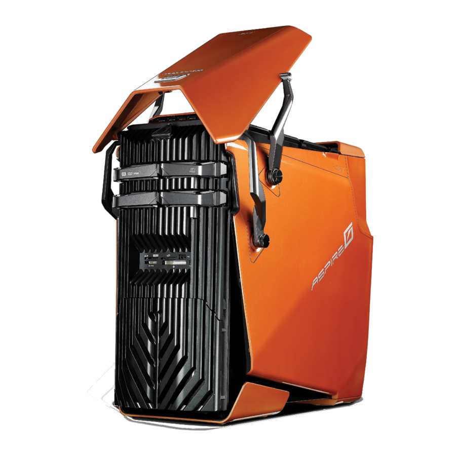
Page 20: External And Internal Structure
2 System tour External and internal structure Closed front panel... - Page 21 Component Hinge screws x 4 Door hinges x 4 Bezel door...
-
Page 22: Front Panel
2 System tour Front panel... - Page 23 Icon Component USB 2.0 ports Microphone/line-in jack Headphone/line-out jack Power button/power indicator Optical disk drives XD (eXtreme Digital) slot USB 2.0 port IEEE 1394 port (4-pin) CF I/II (CompactFlash Type I/II) slot Drive bay door Easy-swap hard disk cartridge (1~4) MS/MS Pro (Memory Stick/Memory Stick Pro Duo) slot SD/MMC (SecureDigital/MultimediaCard) slot Optical disk drive eject buttons...
-
Page 24: Using The Memory Card Reader
Using the memory card reader Your computer supports multi-media card slots. These slots are useful for transferring data to and from the following memory cards to your computer. ® • CompactFlash (Type I and II) ™ • Microdrive • MultiMediaCard (MMC) ™... - Page 25 To remove a memory card: Before ejecting a card: • Exit the application using the card. • Left-click on the Safely Remove Hardware icon on the Windows taskbar and stop the card operation. Gently press the card further into the slot to pop it out. Pull out the card from the slot.
-
Page 26: Rear Panel
2 System tour Rear panel... - Page 27 Icon Component Power supply PS/2 mouse port System fan Network ports Headphone/line-out/front speaker jack Audio-in/line-in jack Expansion slot locks S-video port DVI port Rear speaker jack Center speaker/subwoofer jack Microphone/line-in jack S/PDIF jack USB ports IEEE 1394 port (6-pin) eSATA (External Serial Advanced Technology Attachment) ports Clear CMOS button...
- Page 28 Icon Component PS/2 keyboard port Power connector Main power switch 2 System tour...
-
Page 29: System Board
System board Mainboard... - Page 30 Code Component PWR1 Power connector CPUFAN1 Processor fan cable connector DIMM1~6 System memory slots JPWR1 24-pin ATX power connector SATA1~6 SATA data cable connectors SYSFAN1~5 System fan cable connector F_PANEL1 Front panel connector JUSB1~3 Front USB connectors J1394_1 IEEE 1394 connector JAUD1 Front panel audio connectors PCI1...
- Page 31 Back panel I/O Code Color Mouse Green Keyboard Purple CLR_CMOS eSATA 1394 USB ports CS-Out Orange RS-Out Black S/PDIF Line-In Blue Line-Out Green Pink Component PS/2 mouse port PS/2 keyboard port Clear CMOS button eSATA ports IEEE 1394 port (6-pin) Network ports USB ports Center speaker/subwoofer jack (in 5.1/7.1...
-
Page 32: System Board Switches And Connectors
System board switches and connectors The System board switches are easy to turn off or reset the computer when user testing the system. IDE connector (for selected models) The IDE connector supports IDE hard disk drives, optical disk drives, and other IDE devices. -
Page 33: Serial Ata Connector: Sata1~6
Serial ATA connector: SATA1~6 The six serial ATA connectors (SATA1-6) is a high-speed Serial ATA interface port. Each connector can connect to one Serial ATA device. Important: Please do not fold the Serial ATA cable into 90-degree angle. Otherwise, data loss may occur during transmission. Fan power connectors The fan power connectors (CPUFAN and SYSFAN1-5) support system cooling fan with +12V. -
Page 34: Front Panel Connectors
Front panel connectors The front panel connectors (F_PANEL1) are for electrical connection to the front panel switches and LEDs. F_PANEL1 front panel pin definition SIGNAL Storage_LED + FP PWR/SLP Storage_LED - FP PWR/SLP RST_SW - PWR_SW+ RST_SW + PWR_SW- RSVD_DNU None Serial port connector (for selected models) The serial port connector (JCOM1) is a 16550A high speed communication port... -
Page 35: System Led Indicators
System LED indicators Front and rear panel LED indicators Indicator Location Power Front panel (Power button) Front panel (Easy-swap HDD) Network Rear panel activity (Network port) Network Rear panel link (Network port) Color Status Description Blue System has AC power and is powered on Blinking System is in standby... - Page 36 2 System tour...
-
Page 37: Setting Up Your Computer
3 Setting up your computer... -
Page 38: Arranging A Comfortable Work Area
Arranging a comfortable work area Working safely and comfortably begins with the arrangement of your work space and the proper use of equipment. For this reason, it is very important to take time and think about how you are going to arrange your work area. Refer to the diagram on the following page as you set up your system. -
Page 39: Positioning Your Monitor
Take note of the following when selecting a location for your computer: • Do not put your computer near any equipment that might cause electromagnetic or radio frequency interference, such as radio transmitters, televisions, copy machines or heating and air-conditioning equipment. -
Page 40: Connecting The Computer
Connecting the computer Setting up your computer is easy. For the most part, you only have four things to connect: the mouse, the keyboard, the monitor, and the power cable. Note: The peripherals shown in the connections below are for your reference only. -
Page 41: Connect A Monitor
Connect a monitor To connect a monitor, simply plug the monitor cable into the DVI port located on the rear panel of your computer. If you have a monitor that supports S-video, plug the monitor cable to the S-video port located on the rear panel of your computer. -
Page 42: Individual Network Configuration
Individual network configuration Connect one end of the network cable on the network port on the rear of the computer, then connect the other end of the network cable into the cable modem or network jack or hub on your network. Note: Consult your network system administrator or operating system manual for information on how to configure your network setup. - Page 43 Plug the power cable into the power cable socket located on the rear panel of your computer. Plug the other end of the power cable into a power outlet.
-
Page 44: Turning On Your Computer
3 Setting up your computer Turning on your computer After making sure that you have properly set up the system, applied power, and connected all the necessary peripherals, you can now power on the system. Follow the procedure below. Turn on the main power switch located on the rear of the computer. - Page 45 Press the power button. Important: Make sure that the power cable is properly plugged into an electrical outlet. If you are using a power strip or an AVR (Auto-Voltage Regulator), make sure that it is plugged in and turned on.
-
Page 46: Turning Off Your Computer
Turning off your computer The software procedure below applies to system running a Windows OS. For other OS shutdown procedures, refer to the related user documentation. On the Windows Vista taskbar, click on the Start button, and click then click Shut Down. Turn off all peripherals connected to your computer. -
Page 47: Using Your Desktop
4 Using your desktop... -
Page 48: Using The Keyboard(Optional)
Using the keyboard(optional) The gaming keyboard has several types of keys and buttons. It features blue- backlit characters on every key, 18 programmable G keys, convenient media control buttons, Macro button, separate cursor keys, and 12 function keys that takes care of your everyday keyboarding and gaming requirements. Item USB ports Multimedia keys... - Page 49 Item Windows logo Programmable G keys Macro keys Game mode switch For more information on how to use the Logitech keyboard, refer to the Logitech help files. Description Pressed alone, this key has the same effect as clicking on the Windows Start button; it launches the Start menu.
-
Page 50: Using The Mouse(Optional)
Using the mouse(optional) The mouse controls the pointer movement on the computer display. Item Description Tilt wheel Push wheel to either side to scroll horizontally. Program wheel to mimic keyboard commands. In-game dpi Press button to increase dpi (tracking sensitivity). increase In-game dpi Press button to decrease dpi (tracking sensitivity). -
Page 51: Using The Optical Drive
Using the optical drive Your computer may come with a Blu-ray/HD reader + SuperMulti burner. This drive is located on the front panel of your computer. The BD and HD drive allows you to play not only old CD-ROMs, CD-I disks, and video CDs, DVD-RAM/- RW, DVD-ROMs, DVD+R/-R disks, but play BD disks and HD DVD disk as well. -
Page 52: Taking Care Of Your Optical Disks
When the disk tray slides open, place the disk gently on the tray. Make sure that the label or title side of the disk is facing upward. When holding a disk, hold it by the edges to avoid leaving smudges or fingerprints. -
Page 53: Connecting Options
Connecting options Your computer offers excellent expansion capabilities with its built-in ports and connectors. This section describes how to make connections through various options. When connecting peripherals, read the manual included with the peripheral for operating instructions. Printer You can connect a USB printer to an available USB port . -
Page 54: Esata Devices
eSATA devices The computer’s eSATA (External Serial ATA) port allows you to connect external SATA device. Audio devices Note: The audio devices shown below are for reference only. Actual device models may vary in select countries. Audio devices are easy to connect with the audio ports accessible from the front and rear of the computer. - Page 55 jack (green jack) located on the front and rear of the computer.
-
Page 56: Usb Devices
USB devices Universal Serial Bus (USB) is a serial bus design capable of cascading peripherals such as a digital camera, keyboard, mouse, scanner, printer, modem, flash drives, VoIP phones, and gaming devices (such as joystick, steering wheels, rumble pads, or foot pedals). With USB, complex cable connections can be eliminated. -
Page 57: Connecting A Video Game Console
Connecting a video game console To connect and share Internet connection with a video game console: Before connecting any cables, turn off your computer and video game console. Connect the computer to the network. See page 29 for detailed instructions. Connect one end of the network cable on the network port on the rear of the computer, then connect the other end of the network cable to the network jack on the rear of the video game console. - Page 58 4 Using your desktop...
-
Page 59: Upgrading Your Computer
6 Upgrading your computer... -
Page 60: Installation Precautions
Installation precautions Before you install any computer component, we recommend that you read the following sections. These sections contain important ESD precautions along with preinstallation and post-installation instructions. ESD precautions Electrostatic discharge (ESD) can damage your processor, disk drives, expansion boards, and other components. -
Page 61: Post-Installation Instructions
Post-installation instructions Observe the following after installing a computer component: See to it that the components are installed according to the step-by-step instructions in their respective sections. Replace any expansion boards or peripherals that you removed earlier. Replace the side panel. Replace the bezel door. -
Page 62: Opening Your Aspire G7710
Opening your Aspire G7710 Caution: Before you proceed, make sure that you have turned off your computer and all peripherals connected to it. Read the “Preinstallation instructions” on page 48. You need to open your computer before you can install upgrade components. The side panel is removable to allow access to the computer’s internal components. - Page 63 To install the bezel door: Perform the preinstallation instructions described on page 48. Align the door hinges to the screw holes on the side panels. Secure the hinges on the panels with the four screws you removed earlier.
-
Page 64: Removing And Installing The Side Panel
Removing and installing the side panel To remove the side panel: Remove the bezel door. Refer to the previous section for instructions. Remove the side panel. Release the locks on the rear side Hold the rear edge of the panel with both hands then slide the panel towards the rear of the chassis. - Page 65 To install the side panel: Perform the preinstallation instructions described on page 48. Align the tabs on the panel with the slots on the chassis. Slide the panel toward the front of the chassis until it is fully closed. Lock the side panel.
-
Page 66: Removing And Installing A Hard Drive
Removing and installing a hard drive The computer supports up to four easy-swap hard disk drives. Each hard disk is mounted in a carrier that holds a standard 3.5-inch Serial ATA hard drive and connects to a SATA interface on the disk cage backplane. Aspire G7710’s EasySwap technology allows you to replace hard drives without powering down the system. - Page 67 If you are replacing a hard disk, remove the four screws that secure the hard disk to the carrier (1), then remove the disk from the carrier (2). Keep the screws for later installation. To install a new hard drive to an empty carrier: Perform steps 1 through 5 of the previous section.
- Page 68 Make sure that the drive is properly inserted before pushing the handle back until it clicks into place. Set up the new hard drive’s RAID configuration. 6 Upgrading your computer...
-
Page 69: Removing And Installing An Optical Drive
Removing and installing an optical drive The system supports a variety of storage devices for additional storage capacity and scalability. To remove an optical drive: Perform the preinstallation instructions described on page 48. Remove the front bazel. Disconnect the power and data cables from rear of the old drive. Move the release slider of the selected drive to the unlock position. -
Page 70: Upgrading The System Memory
Upgrading the system memory This section explains the procedures for removing and installing a memory module. System memory interface The six 240-pin sockets on the mainboard support Double Data Rate 2 (DDR2) Synchronous Dynamic Random Access Memory (SDRAM)-type DIMMs. You may install 1 GB or 2 GB DIMMs for a maximum memory capacity of 12 GB. -
Page 71: System Memory Configuration Guidelines
System memory configuration guidelines • To ensure data integrity, use only Acer-approved modules in 1 GB or 2 GB capacities. • Use identical modules — same specification for size, speed, and organization. • In minimum configuration, the FDB should be installed in DIMM 2 slot. -
Page 72: To Remove A Memory Module
To remove a memory module: Observe the ESD precautions described on page 48. Lay the system on its side (components showing). Press the holding clips on both sides of the DIMM slot outward to release the DIMM (1). Gently pull the DIMM upward to remove it from the DIMM slot (2). If you intend to install a new memory module, proceed to the next section for related procedure, then observe the post-installation instructions described on page 49. - Page 73 Align the DIMM so that the notch on the slot fits the keyed edge of the module, then press the module at both ends to seat it fully into the slot (1). If you insert a DIMM but it does not fit easily into the slot, you have inserted it incorrectly.
-
Page 74: Installing An Expansion Card
Installing an expansion card This section explains how to install an expansion card and a second CrossFire- Ready graphic card. PCI bus slots interface 3 PCI Express x16 slots compatible with PCIE 2.0 specification, supports CrossFire mode. • The mazarine PCIE x16 (PCI_EX1, 3, 5) slot supports PCIE x16 speed •... - Page 75 Caution: Do not discard the slot cover. If the expansion card is removed in the future, the slot cover must be reinstalled to maintain proper system cooling. Remove the expansion card from its protective packaging, handling it by the edges. Insert the card into the selected slot.
- Page 76 of the case. This back plate will go where the tabs used to be. Press the release latch to secure the card in place. Locate the second PCI Express power cord from the CrossFire-Ready power supply and plug it in to the second graphic card. Attach the CrossFire connector to connect the two graphic cards.
-
Page 77: Acer Empowering Technology
5 Acer Empowering Technology... -
Page 78: Acer Empowering Technology
Acer Empowering Technology The Empowering Technology toolbar makes it easy for you to access frequently used functions and manage your new Acer system. Displayed by default in the upper half of your screen, it provides access to the following utility: Acer eRecovery Management backs up and recovers data flexibly, reliably and completely. - Page 79 • Restore and recovery • Factory default image • User backup image • From previously-created CD/DVD • Reinstall applications/drivers...
- Page 80 5 Acer Empowering Technology...
-
Page 81: Frequently Asked Questions
7 Frequently asked questions... -
Page 82: Frequently Asked Questions
Note: For more information about recovering your system, see “Acer eRecovery Management” on page 66. Nothing appears on the screen. Your computer's power management function automatically blanks the screen to save power. -
Page 83: The Printer Does Not Work
The printer does not work. Do the following: • Make sure the printer is connected to a power outlet and that it is turned on. • For additional information concerning the printer, refer to the printer's documentation. No sound comes out from the computer. Check the following: •... -
Page 84: Recovering Your System
OS unstable or unusable. After the POST runs, Press Alt + F10 combine key during BIOS to enter hidden partition. This utility has same password protection with Acer eRecovery. Follow all onscreen instructions. 7 Frequently asked questions... - Page 85 You can also follow the steps below: Click the eRecovery icon in the Empowering Technology toolbar. You can change the password in Acer eRecovery. If you have not yet backed-up your system.
- Page 86 If you have previously backed-up your system. Select “Recover to Default Settings” to restore your system to the default factory settings. Select “Recover data from last backup” to restore your system to the last system backup. If you chose the recovery option, you should see the following screen. Click OK to continue.
- Page 87 After 15 seconds the system will reboot and initiate the restore operation. After the recovery operation finishes the system will reboot. You will be required to go through the setup process again. Caution! Running the Recovery operation will erase all files previously saved in your computer so make sure to back up your important files before starting the recovery process.
- Page 88 7 Frequently asked questions...
-
Page 89: Regulations And Safety Notices
8 Regulations and safety notices... -
Page 90: Regulations And Safety Notices
Regulations and safety notices FCC notice This device has been tested and found to comply with the limits for a Class B digital device pursuant to Part 15 of the FCC rules. These limits are designed to provide reasonable protection against harmful interference in a residential installation. -
Page 91: Modem Notices
Cet appareil numérique de la classe B est conforme a la norme NMB-003 du Canada. Declaration of Conformity for EU countries Hereby, Acer, declares that this PC series is in compliance with the essential requirements and other relevant provisions of Directive 1999/5/EC. (Please visit http://global.acer.com/support/certificate.htm for complete documents.) -
Page 92: Notice For Australia
If this equipment should fail to operate properly, disconnect the equipment from the phone line to determine if it is causing the problem. If the problem is with the equipment, discontinue use and contact your dealer or vendor. Caution: To reduce the risk of fire, use only No. 26 AWG or larger UL Listed or CSA Certified Telecommunication Line Cord. -
Page 93: Laser Compliance Statement
Some parameters required for compliance with Telecom's Telepermit requirements are dependent on the equipment (PC) associated with this device. The associated equipment shall be set to operate within the following limits for compliance with Telecom's Specifications: • There shall be no more than 10 call attempts to the same number within any 30 minute period for any single manual call initiation, and •... -
Page 94: Lcd Pixel Statement
PRODUCTO LÁSER DE LA CLASE I ADVERTENCIA: RADIACIÓN LÁSER INVISIBLE AL SER ABIERTO. EVITE EXPONERSE A LOS RAYOS. ADVARSEL: LASERSTRÅLING VEDÅBNING SE IKKE IND I STRÅLEN. VARO! LAVATTAESSA OLET ALTTINA LASERSÅTEILYLLE. VARNING: LASERSTRÅLNING NÅR DENNA DEL ÅR ÖPPNAD ÅLÅ TUIJOTA SÅTEESEENSTIRRA EJ IN I STRÅLEN VARNING: LASERSTRÅLNING NAR DENNA DEL ÅR ÖPPNADSTIRRA EJ IN I STRÅLEN... - Page 95 • EN301 489-17 V1.2.1:2002 • EN301 489-3 V1.4.1:2002 (Applied to models with 27MHz wireless mouse/keyboard) • EN301 489-7 V1.2.1:2002 (Applied to models with 3G function) • EN301 489-24 V1.2.1:2002 (Applied to models with 3G function) • Article 3.2 Spectrum Usages •...
-
Page 96: The Fcc Rf Safety Requirement
The FCC RF safety requirement The radiated output power of the wireless LAN Card and Bluetooth card is far below the FCC radio frequency exposure limits. Nevertheless, the PC series shall be used in such a manner that the potential for human contact during normal operation is minimized as follows: This device is restricted to indoor use due to its operation in the 5.15 to 5.25 GHz frequency range. -
Page 97: Federal Communications Commission Declaration Of Conformity
The following local Manufacturer/Importer is responsible for this declaration: Product: Model number: Name of responsible party: Address of responsible party: Contact person: Tel: Fax: Personal Computer Aspire G Series Acer America Corporation 333 West San Carlos St. San Jose, CA 95110 U. S. A. Acer Representative 254-298-4000 254-298-4147... - Page 98 Declaration of Conformity Acer Computer (Shanghai) Limited 3F, No. 168 Xizang medium road, Huangpu District, Shanghai, China Contact Person: Mr. Easy Lai Tel: 886-2-8691-3089 Fax: 886-2-8691-3000 E-mail: easy_lai@acer.com.tw Hereby declare that: Product: Personal Computer Trade Name: Acer Model Number: Aspire G Series...
- Page 99 EN300 220-3 V2.1.1 (Short range device, 25~1000MHz, part 3.) • EN300 328 V1.6.1 (Data transmission equipment operating in the 2.4 • GHz ISM band) EN301 893 V1.2.3 (5GHz high performance RLAN) • Easy Lai, Director Acer Computer (Shanghai) Limited Nov. 2008 Date...
- Page 100 8 Regulations and safety notices...
-
Page 101: Index
Index accessing the online User’s Guide Acer Empowering Technology password setup Acer eRecovery Management bezel door install remove connecting options 1394 device audio devices analog speakers external speakers microphone eSATA devices network printer USB devices disk drives CD-ROM/DVD-ROM/CD-RW/BD/ HD-DVD drive... - Page 102 modem notices setting up computer area chair connect broadband network external monitor keyboard mouse connecting power cable keyboard monitor mouse side panel install remove system board audio card connectors mainboard switches system memory install turning off computer software shutdown suspend mode turning on computer power button power switch...