ABB ACS320 series User Manual
Hide thumbs
Also See for ACS320 series:
- User manual (442 pages) ,
- Supplemental manual (16 pages) ,
- Installation instructions (4 pages)

Related Manuals for ABB ACS320 series


Summary of Contents for ABB ACS320 series
- Page 1 ABB industry-specific drives Short form user’s manual ACS320 drives Table of contents Safety Mechanical installation Electrical installation Start-up and control with I/O...
-
Page 2: List Of Related Manuals
ACS320 user’s manual (3AUA0000062599 [English]). To access it on the Internet, go to www.abb.com/drives, select Document Library, enter the code in the search field and click OK. Applicability The manual is applicable to the ACS320 drive firmware version 4.03c or later. -
Page 3: Table Of Contents
Table of contents 3 Table of contents List of related manuals ............2 Purpose of the manual . - Page 4 Providing feedback on ABB Drives manuals ........
-
Page 5: Safety
Safety 5 1. Safety Safety in installation and maintenance These warnings are intended for all who work on the drive, motor cable or motor. Electrical safety WARNING! Ignoring the following instructions can cause physical injury or death, or damage to the equipment. •... -
Page 6: Safe Start-Up And Operation
Note: • Even when the motor is stopped, dangerous voltage is present at the power circuit terminals U1, V1, W1 and U2, V2, W2. • For more technical information, contact the factory or your local ABB sales representative. General safety WARNING! If you ignore the safety instructions, injury or death can occur. - Page 7 Safety 7 Note: • If an external source is selected for start command, and it is ON, the drive starts immediately after an input voltage break or fault reset unless the drive is configured for 3-wire (a pulse) start/stop. • When the control location is not set to local (LOC not shown on the display), the stop key on the control panel will not stop the drive.
- Page 8 8 Safety...
-
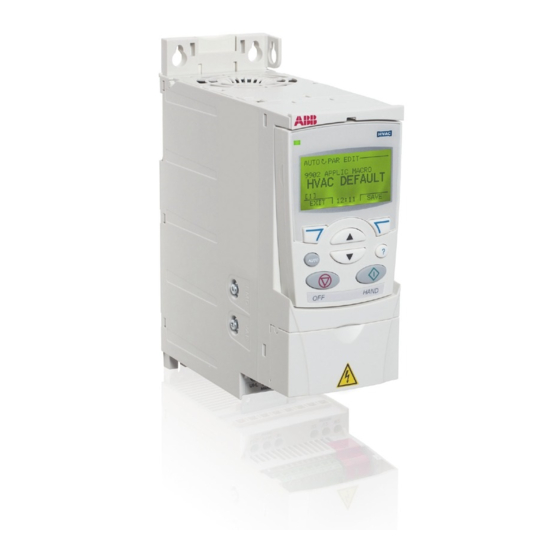
Page 9: Hardware Description
Hardware description 9 2. Hardware description Power connections and control interfaces Control panel (RJ-45) Screen AO 7 Analog input 1 Analog output 0…10 V 0…20 mA GND 8 Reference voltage +10V +10 V DC, max. 10 mA Analog input 2 +24 V PROGRAMMABLE RELAY Aux. -
Page 10: Type Designation Label
A, B, C, … for product revision number XXXX: Integer starting every week from 0001 5 ABB MRP code of the drive 6 CE marking and C-Tick, C-UL US and RoHS marks (the label of your drive shows the valid markings) -
Page 11: Type Designation Key
Hardware description 11 Type designation key The type designation contains information on the specifications and configuration of the drive. You find the type designation on the type designation label attached to the drive. The first digits from the left express the basic configuration, for example, ACS320-03E-08A8-4. - Page 12 12 Hardware description...
-
Page 13: Mechanical Installation
Mechanical installation 13 3. Mechanical installation Installing The instructions in this manual cover drives with the IP20 degree of protection. To comply with NEMA 1, use the MUL1-R1, MUL1-R3 or MUL1-R4 option kit, which is delivered with multilingual installation instructions (3AFE68642868, 3AFE68643147 or 3AUA0000025916, respectively). - Page 14 14 Mechanical installation 3. Position the drive onto the screws on the wall. 4. Tighten the screws in the wall securely. On DIN rail • Click the drive to the rail. • To detach the drive, press the release lever on top of the drive (1b).
- Page 15 Mechanical installation 15 Fasten clamping plates 1. Fasten the clamping plate to the plate at the bottom of the drive with the provided screws. 2. For frame sizes R0…R2, fasten the I/O clamping plate to the clamping plate with the provided screws.
- Page 16 16 Mechanical installation...
-
Page 17: Electrical Installation
Electrical installation 17 4. Electrical installation WARNING! Obey the safety instructions. See chapter Safety on page 5. If you ignore the safety instructions, injury or death can occur. If you are not a qualified electrician, do not do electrical work. Make sure that the drive is disconnected from the input power during installation. - Page 18 18 Electrical installation Note: In frame size R4 the EMC screw is located to the right of terminal W2.
-
Page 19: Connecting The Power Cables
Electrical installation 19 Connecting the power cables Connection diagram Drive INPUT OUTPUT U1/L V1/N W1 U2 V2 W2 For alternatives, see chapter Planning the electrical installation, section Selecting the supply disconnecting device (disconnecting means) in ACS320 user’s Motor manual (3AUA0000062599 [English]). - Page 20 20 Electrical installation Connection procedure 1. Fasten the grounding conductor (PE) of the input power cable under the grounding clamp. Connect the phase conductors to the U1, V1 and W1 terminals. Use a tightening torque of 0.8 N·m (7 lbf·in) for frame sizes R0…R2, 1.7 N·m (15 lbf·in) for R3, and 2.5 N·m (22 lbf·in) for R4.
-
Page 21: Connecting The Control Cables
Electrical installation 21 Connecting the control cables Default I/O connection diagram The default connection of the control signals depends on the application macro in use, which is selected with parameter 9902 APPLIC MACRO. The default macro is the HVAC Default macro. It provides a general purpose I/O configuration with three constant speeds. - Page 22 22 Electrical installation Connection procedure 1. Remove the terminal cover by simultaneously pushing the recess and sliding the cover off the frame. 2. Digital signals: Strip the outer insulation of the digital signal cable 360 degrees and ground the bare shield under the clamp. 3.
-
Page 23: Installation Checklist
Electrical installation 23 Installation checklist Check the mechanical and electrical installation of the drive before start-up. Go through the checklist below together with another person. Read chapter Safety page before you work on the drive. Check MECHANICAL INSTALLATION The ambient operating conditions are within allowed limits. (See Technical data: Losses, cooling data and noise and Ambient conditions in ACS320 user’s manual (3AUA0000062599 [English]).) The drive is fixed properly on an even vertical non-flammable wall. - Page 24 24 Electrical installation...
-
Page 25: Start-Up And Control With I/O
Start-up and control with I/O 25 5. Start-up and control with I/O How to start up the drive WARNING! Only qualified electricians are allowed to start-up or operate the drive. Obey the safety instructions. See chapter Safety on page 5. Before adjusting the drive and putting it into service, make sure that the motor and all driven equipments are suitable for operation throughout the speed range provided by the drive. - Page 26 Enter the motor data from the motor nameplate: Note: Set the motor data to exactly the same value as on the motor nameplate. For ABB Motors example, if the nominal motor speed is 1470 rpm on the motor M2AA 200 MLA 4...
- Page 27 Start-up and control with I/O 27 • nominal motor voltage (parameter 9905) 9905 Setting of parameter 9905 is shown below as an example of parameter setting with the Basic control panel. You find more detailed instructions in chapter Control panels, section Basic control panel in ACS320 user’s manual (3AUA0000062599 [English]).
- Page 28 28 Start-up and control with I/O DIRECTION OF THE MOTOR ROTATION Check the direction of the motor rotation. • If the drive is in remote control (REM shown on the left), switch to local control by pressing • To go to the Main menu, press if the bottom line shows OUTPUT;...
- Page 29 Start-up and control with I/O 29 How to perform a guided start-up To be able to perform the guided start-up, you need the Advanced HVAC control panel. Before you start, make sure that you have the motor nameplate data on hand. POWER-UP Apply input power.
- Page 30 30 Start-up and control with I/O Select the application macro according to which the PAR EDIT control cables are connected. 9902 APPLIC MACRO HVAC DEFAULT 00:00 EXIT SAVE Continue with the application set-up. After CHOICE Do you want to completing a set-up task, the Start-up assistant continue with suggests the next one.
- Page 31 Start-up and control with I/O 31 FINAL CHECK After the whole set-up is completed, check that there are no faults or alarms shown on the display and the panel LED is green and does not blink. The drive is now ready for use.
-
Page 32: How To Control The Drive Through The I/O Interface
32 Start-up and control with I/O How to control the drive through the I/O interface The table below instructs how to operate the drive through the digital and analog inputs when: • the motor start-up is performed, and • the default (standard) parameter settings are valid. The below examples show the Basic control panel display. -
Page 33: Actual Signals And Parameters In The Short View
Actual signals and parameters in the short view 33 6. Actual signals and parameters in the short view Note: When the control panel is in the short parameter view, that is when parameter 1611 PARAMETER VIEW is set to 2 (SHORT VIEW), the control panel only shows a subset of all signals and parameters. -
Page 34: Default Values With Different Macros
34 Actual signals and parameters in the short view Default values with different macros When application macro is changed (9902 APPLIC MACRO), the software updates the parameter values to their default values. The table below shows the parameter default values for different macros. For other parameters, the default values are the same for all macros. - Page 35 0 = 8 NONE 1 0 = 8 NONE 1 5305 EFB CTRL 0 = ABB 0 = ABB 0 = ABB 0 = ABB 0 = ABB DRV 0 = ABB 0 = ABB DRV 0 = ABB DRV PROFILE DRV LIM...
- Page 36 36 Actual signals and parameters in the short view Index Name/ INT TIMER CS FLOATING DUAL DL SP PID E-BYPASS HAND E-CLIPSE AC500 Selection SETPPID CONTROL MODBUS 9902 APPLIC 9 = INT 10 = 11 = DUAL 12 = DL SP 13 = E- 14 = HAND 15 =...
- Page 37 0 = 8 NONE 0 = 8 NONE 2 = 8 EVEN 0 = 8 NONE 1 5305 EFB CTRL 0 = ABB DRV 0 = ABB DRV 0 = ABB 0 = ABB 0 = ABB 0 = ABB...
-
Page 38: Actual Signals In The Short Parameter View
38 Actual signals and parameters in the short view Actual signals in the short parameter view Actual signals in the short parameter view Name/Value Description FbEq 04 FAULT HISTORY Fault history (read-only) 0401 LAST FAULT Code of the latest fault. See chapter Fault tracing in 1 = 1 ACS320 user’s manual (3AUA0000062599 [English]) for the codes. -
Page 39: Parameters In The Short Parameter View
Actual signals and parameters in the short view 39 Parameters in the short parameter view Parameters in the short parameter view Name/Value Description Def/FbEq 11 REFERENCE Panel reference type, external control location selection and SELECT external reference sources and limits 1105 REF1 MAX Defines the maximum value for external reference REF1. - Page 40 40 Actual signals and parameters in the short view Parameters in the short parameter view Name/Value Description Def/FbEq 14 RELAY OUTPUTS Status information indicated through relay output, and relay operating delays. For more information, see chapter Actual signals and parameters in ACS320 user’s manual (3AUA0000062599 [English]).
- Page 41 Actual signals and parameters in the short view 41 Parameters in the short parameter view Name/Value Description Def/FbEq 22 ACCEL/DECEL Acceleration and deceleration times 2202 ACCELER Defines the acceleration time 1, i.e., the time required for 30.0 s TIME 1 the speed to change from zero to the speed defined by parameter 2008 MAXIMUM...
- Page 42 5305 EFB CTRL Selects the communication profile. ABB DRV PROFILE ABB DRV LIM Operation of Control/Status words conforms to ABB Drives Profile. DCU PROFILE Operation of Control/Status words conforms to 32-bit DCU profile. ABB DRV Operation of Control/Status words conforms to ABB Drives FULL Profile.
- Page 43 For Modbus: Sets an additional delay before the drive begins transmitting response to the master request. 5319 EFB PAR 19 ABB drives profile (ABB DRV LIM or ABB DRV FULL) 0000 hex Control word. Read only copy of the Fieldbus Control word.
- Page 44 44 Actual signals and parameters in the short view Parameters in the short parameter view Name/Value Description Def/FbEq RUSSKI Russian POLSKI Polish TÜRKÇE Turkish CZECH Czech MAGYAR Hungarian ELLINIKA Greek CHINESE Chinese KOREAN Korean JAPANESE Japanese 9902 APPLIC Selects the application macro. See chapter Application HVAC MACRO macros in ACS320 user’s manual (3AUA0000062599...
- Page 45 Actual signals and parameters in the short view 45 Parameters in the short parameter view Name/Value Description Def/FbEq AC500 This macro configures the drive communication and control MODBUS parameters. 9905 MOTOR NOM Defines the nominal motor voltage. Must be equal to the 200 V VOLT value on the motor rating plate.
- Page 46 46 Actual signals and parameters in the short view...
-
Page 47: Technical Data
Technical data 47 7. Technical data Ratings Note: When choke is not used, input current is effected by supply network and impedance. Use the table in Fuses and alternate short-circuit protection (page 50) to correctly size the input cabling as well as input fuses or MMP for branch circuit protection. Sizing will be determined by the actual input current which is dependent on the input line voltage and the input choke selection and rated motor current. -
Page 48: Definitions
48 Technical data Type code Input Output Frame size without choke with choke or or reactor 5% reactor ACS320- 2max (480 V) (480 V) x = E/U 03x-04A1-4 03x-05A6-4 10.6 03x-07A3-4 12.8 10.7 12.8 03x-08A8-4 15.0 12.5 15.4 03x-12A5-4 20.7 17.2 12.3 10.3... - Page 49 Technical data 49 Sizing Drive sizing is based on the rated motor current and power. To achieve the rated motor power given in the table, the rated current of the drive must be higher than or equal to the rated motor current. The rated power of the drive must also be higher than or equal to compared to the rated motor power.
-
Page 50: Fuses And Alternate Short-Circuit Protection
65 kA RMS symmetrical amperes at the drive maximum rated voltage. See the appropriate ratings in the following table. IP20 open type and IP21 UL type 1 ACS320 can use ABB type E manual motor protectors for branch circuit protection. See the MMP rating table for the minimum... - Page 51 Technical data 51 Fuses and MMPs Type Fuses MMPs ACS320- UL Class T or Frame Min. Encl. CC (600 V) MMP Type E Vol. x = E/U min A max A 1-phase U = 200…240 V (200, 208, 220, 230, 240 V) 01x-02A4-2 MS132-6.3 &...
- Page 52 For UL only: The minimum enclosure volume is specified in the UL listing for drive frames R0 and R1 when applied with the ABB type E MMP shown in the table. ACS320 drives are intended to be mounted in an...
-
Page 53: Ul Marking
Technical data 53 UL marking See the type designation label for the valid markings of your drive. The UL mark is attached to the drive to verify that it meets UL requirements. UL checklist See the instructions for electrical installation in the sections in this manual or in the ACS320 user’s manual (3AUA0000062599 [English]0 specified below. - Page 54 54 Technical data...
- Page 55 Technical data 55...
- Page 56 56 Technical data...
-
Page 57: Product And Service Inquiries
Product and service inquiries Address any inquiries about the product to your local ABB representative, quoting the type designation and serial number of the unit in question. A listing of ABB sales, support and service contacts can be found by navigating to www.abb.com/searchchannels.