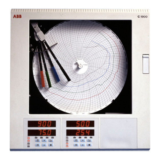
ABB C1900 Series Installation Manual
Informit circular chart recorder and recorder/controller
Hide thumbs
Also See for C1900 Series:
- Operating manual (44 pages) ,
- Installation manual (28 pages) ,
- User manual (20 pages)

Related Manuals for ABB C1900 Series


Summary of Contents for ABB C1900 Series
- Page 1 Inform Installation Guide IM/C1900–INS_10 Circular Chart Recorder and Recorder/Controller C1900 Series...
- Page 2 Cert. No. Q 05907 As a part of ABB, a world leader in process automation technology, we offer customers application expertise, service and support worldwide. EN 29001 (ISO 9001) We are committed to teamwork, high quality manufacturing, advanced technology and unrivalled service and support.
-
Page 3: Table Of Contents
CONTENTS 1 INTRODUCTION The series of COMMANDER 1900 instruction manuals is shown Section Page in Fig. 1.1. The , including the specification Standard Manuals sheet, are supplied with all instruments. The Supplementary INTRODUCTION ............1 supplied depend on the specification of the instrument. Manuals PREPARATION ............. -
Page 4: Preparation
2 PREPARATION 2.1 Accessories – Fig. 2.1 2.2 Checking the Code Number – Fig. 2.2 2.2.1 Non-upgradeable Version Note. The 1901J is a basic, non-upgradeable single pen recorder. This version is not fitted with an analog output, relay, transmitter power supply unit or digital inputs and no additional modules can be fitted. -
Page 5: Mechanical Installation
3 MECHANICAL INSTALLATION 3.1 Siting – Figs 3.1 and 3.2 3.2 Mounting – Figs. 3.3 to 3.5 Dimensions in inches (mm) Minimum Sensor 15.04 (382) A – Close to Sensor 15.23 (386.8) B – At Eye-level Location C – Avoid Vibration 1.30 (33) Fig. -
Page 6: Wall-/Pipe-Mounting
…3 MECHANICAL INSTALLATION 3.2.1 Wall-/Pipe-Mounting – Fig. 3.4 Mark fixing centers on wall (4) . 8 1 ( 3 7 6 . 3 . 0 6 ( 2 8 1 . 0 Drill suitable holes (4) Secure mounting brackets (4) to case Secure instrument to wall using suitable fixings A –... -
Page 7: Panel Mounting
3 MECHANICAL INSTALLATION 3.2.2 Panel Mounting – Fig. 3.5 Dimensions in inches (mm) Drill four suitable holes 4 holes 0.281 dia. or tap for thread Mark four mounting holes 14.00 (355.6) 12.72 (323.08) minimum 14.19 11.25 (360.4) 12.72 (285.8) (323.1) minimum 1.70 (43.2) -
Page 8: Electrical Installation
4 ELECTRICAL INSTALLATION Warnings. • Instruments not fitted with the optional internal on/off switch and fuse must have a disconnecting device such as a switch or circuit breaker conforming to local safety standards fitted to the final installation. It must be fitted in close proximity to the instrument within easy reach of the operator and must be marked clearly as the disconnection device for the instrument. -
Page 9: Identifying The Input/Output Modules
4 ELECTRICAL INSTALLATION… 4.1 Identifying the Input/Output Modules – Fig. 4.2 To gain access to the modules, open the door and chassis – see Fig. 2.2. There are six module positions as shown in Fig. 4.2. 4.2 Channel Connections are made directly to the terminal block Channel 1 connections mounted on the motherboard. -
Page 10: Selecting The Analog Input Type(S)
…4 ELECTRICAL INSTALLATION 4.2.1 Selecting the Analog Input Type(s) – Figs. 4.3 and 4.4 Plug-in links are used to select the input type: PL1 & PL8 on the main p.c.b. (Fig. 4.3) Channel 1 PL1 & PL3 on the module (Fig. 4.4) Channels 2 to 4 TR10 mV THC... -
Page 11: Voltage And Current
4 ELECTRICAL INSTALLATION… 4.2.2 Voltage and Current – Fig. 4.5 4.2.5 Resistance Thermometer (RTD) – Fig. 4.5 Input impedances: If long leads are necessary it is preferable to use a 3-lead Low voltage (mV) >10MΩ resistance thermometer. Voltage >10MΩ If 2-lead resistance thermometers are used each input must be Current (mA) 100Ω... -
Page 12: Motorized Valve
…4 ELECTRICAL INSTALLATION 4.2.9 Motorized Valve – Fig. 4.6 A motorized valve with or without feedback requires 2 relays (common and normally open terminals) to drive the valve in either direction. Any two relays can be allocated for this function. Fig. 4.6 A shows two possible combinations. Note. -
Page 13: Module Connections
4 ELECTRICAL INSTALLATION… 4.3 Module Connections 4.3.3 Eight Digital Inputs or Outputs (Module Types 4 and 5 respectively) – 4.3.1 Standard I/O or Analog + Relay Figs. 4.8 and 4.9 (Module Types 1, 2 and 7) – Fig. 4.5 A plug-in link is used to select the board's function; digital inputs The connections are the same as Channel connections to the or digital outputs –... - Page 14 …4 ELECTRICAL INSTALLATION 4.4 Power Supply Selection and AC Connections – Fig. 4.10 1 or 4 Digit 10 Code Label 1 9 x x x x x x x x x x x x x x 3 or 6 2 or 5 Selector not Fitted on 24V AC A –...
-
Page 15: Power Supply Selection And Ac Connections
5 INSTALLATION RECORD... - Page 16 …5 INSTALLATION RECORD...
- Page 17 NOTES...
- Page 18 …NOTES...
- Page 19 Service and Repair Centre. – Food & Beverage – Manufacturing United Kingdom – Metals and Minerals – Oil, Gas & Petrochemical ABB Limited – Pulp and Paper Tel: +44 (0)1480 475321 Fax: +44 (0)1480 217948 Drives and Motors United States of America •...
- Page 20 ABB has Sales & Customer Support The Company’s policy is one of continuous product improvement and the right is reserved to modify the expertise in over 100 countries worldwide information contained herein without notice. www.abb.com Printed in UK (05.05) © ABB 2005 ABB Limited ABB Inc.