Siemens SIMATIC TI505 User Manual
Smart slice
discrete i/o module
Hide thumbs
Also See for SIMATIC TI505:
- User manual (127 pages) ,
- Installation and operation manual (66 pages) ,
- User manual (94 pages)

Related Manuals for Siemens SIMATIC TI505


Summary of Contents for Siemens SIMATIC TI505
- Page 1 SIMATIC TI505 Smart Slice Discrete I/O Module User Manual Order Number: PPX:505–8105–2 Manual Assembly Number: 2586546–0063 Second Edition...
- Page 2 Technical data is subject to change. contents is not permitted without express consent of Siemens Industrial Automation, Inc. All rights, including rights We check the contents of every manual for accuracy at the created by patent grant or registration of a utility model or time it is approved for printing;...
- Page 3 MANUAL PUBLICATION HISTORY SIMATIC TI505 Smart Slice Discrete I/O Module User Manual Order Manual Number: PPX:505–8105–2 Refer to this history in all correspondence and/or discussion about this manual. Event Date Description Original Issue 02/93 Original Issue (2591744–0001) Second Edition 08/93...
- Page 4 LIST OF EFFECTIVE PAGES Pages Description Pages Description Cover/Copyright Second History/Effective Pages Second iii — vii Second 1-1 — 1-2 Second 2-1 — 2-7 Second 3-1 — 3-3 Second 4-1 — 4-3 Second A-1 — A-2 Second Registration Second...
-
Page 5: Table Of Contents
Contents Preface Chapter 1 Product Overview Features ............... . Chapter 2 Installing the Module Overview of Installation . - Page 6 List of Figures SIMATIC TI505 Smart Slice I/O Module ..........
- Page 7 List of Tables I/O Configuration ............. . . Addressing Example .
-
Page 8: Preface
Series 505 products have been developed with consideration of the draft standard of the International Electrotechnical Commission Committee proposed standard (IEC-65A/WG6) for programmable controllers. Contact Siemens Industrial Automation, Inc., for a listing of the standards to which Series 505 complies. Telephoning for... -
Page 9: Chapter 1 Product Overview
Chapter 1 Product Overview Features ............... . Product Overview... -
Page 10: Features
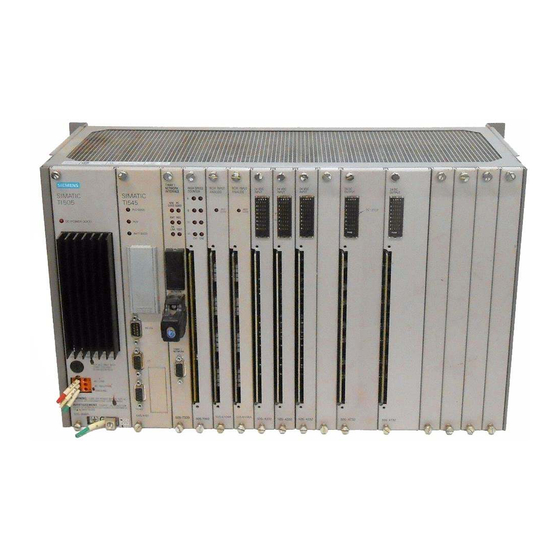
Features The SIMATIC TI505 Smart Slice I/O module (shown in Figure 1-1) allows access to input and output points that are not located near a TI500/TI505 base. The module attaches directly to the RS–485 remote I/O link and emulates a remote base. The module has ten inputs and six outputs. Power is derived from field excitation voltage. - Page 11 Chapter 2 Installing the Module Overview of Installation ............Flow of Tasks .
-
Page 12: Overview Of Installation
Power up Figure 2-1 Flowchart of Installation Visual Inspection If there is any visible damage to the module, contact your Siemens Industrial Automation, Inc. distributor or sales office. If you need assistance in contacting your U.S. sales office, call 1–800–964–4114. -
Page 13: Field Wiring Guidelines
Field Wiring Guidelines WARNING To minimize the potential risk of injury to personnel or damage to the system, use supply wires suitable for at least 75 C. Signal wiring connected to this module must be rated at least 300 V. ATTENTION Employer des fils d’alimentation pour au moins 75 C. -
Page 14: Terminal Block
Terminal Block The module is equipped with a 38-position, removable terminal block. All field wiring is connected to this terminal block. The terminal block accepts wires between 14 and 22 AWG. The terminal block is covered with a hinged shroud, which has a terminal identification label on the inside. -
Page 15: Communication
Internal External Line + Neutral – input circuit I003041 Figure 2-3 Input Wiring Communication The three right-most terminals are dedicated to the connection of the RS–485 communication cable that is connected to the system controller. Refer to Section 2.5 for communications cable configuration. LED status window Identification label PPX:505–9201... -
Page 16: Mounting The Module
Mounting the Module Mounting Tabs Use the mounting tabs to secure the module. The tabs accept #8–32 screws. Clearance for Allow one inch of space around the module to allow for sufficient air flow. Cooling Figure 2-5 shows mounting dimensions. 8.80 8.37 0.21... -
Page 17: Communications Cable Configuration
Communications Cable Configuration Installing Install a terminating resistor across the DATA+ and DATA– terminals. If Terminating your application involves a series of Smart Slices, install a terminating Resistors resistor on the Smart Slice on the end. If your application uses only one Smart Slice, install a terminating resistor on that one. - Page 18 Chapter 3 Programming and Assigning I/O Points Programming the Controller ........... . . Logging the Module into the Controller .
-
Page 19: Programming The Controller
Programming the Controller Refer to the program design manual for your controller for specific details on designing a program. The Smart Slice appears to the controller as a high-density, 16-point input and 8-point output module as shown in Table 3-1. Since the Smart Slice has 10 inputs and 6 outputs, the balance of 6 input points and 2 output points are not used in the I/O configuration table. -
Page 20: Logging The Module Into The Controller
Logging the Module into the Controller Selecting the I/O Figure 3-1 shows a sample I/O definition chart with a module designated Definition Chart with address 01. Refer to your TISOFT manual for detailed instructions. I/O Address Base Number The module is logged in as Displays the unique base address 16 inputs and 8 outputs. -
Page 21: I/O Status Indicators
Chapter 4 Troubleshooting Status Indicators ..............Module Status Indicators . -
Page 22: Status Indicators
The FUSE indicator turns on when the fuse is blown. You also can determine the status of the fuses by using RLL to check the module fail bit in the controller. (See your SIMATIC TI505 Programmable Controller manual.) I/O Status There are six output status LEDs. -
Page 23: Replacing The Fuse
Replacing the Fuse WARNING To minimize the potential risk of injury to personnel or damage to the system, ensure that all user-supplied power is disconnected from the module before attempting the replace the fuse. The fuse is located in the rear of the module, through an access opening. Use an 8 A, 250 VAC 5 20 mm normal-blow replacement fuse. -
Page 24: Appendix A Specifications
Appendix A Specifications Table A-1 Electrical Specifications Specification PPX:505–9201 PPX:505–9202 Description 24 VDC, 10 inputs/6 outputs 110 VAC, 10 inputs/6 outputs Rated voltage 20–30 VDC 90–132 VAC, 47–63 Hz Input type Sinking, high-side common Sinking, high-side common Input on voltage range 15 VDC min, 30 VDC max 79 VAC min, 132 VAC max Input on current range... -
Page 25: Derating For Both Models
Table A-2 Environmental Specifications Wire gauge 14–22 AWG Spade lug for use with connector Amp part number 321462 Ring lug for use with connector Amp part number 327891 Operating temperature 0 to 60 C (32 to 140 F) Storage temperature –40 to +70 C (–40 to 158 F) Relative humidity 5% to 95% noncondensing... - Page 26 SIMATIC is a trademark of Siemens AG. Series 505 and TISOFT are trademarks of Siemens Industrial Automation, Inc. TI500, TI505, TI545, TI560T and TI565T are trademarks of Texas Instruments Incorporated. UL is a registered trademark of Underwriters Laboratories, Inc. CSA is a registered trademark of Canadian Standards Association...
- Page 27 Yes! Please send me a questionnaire. No. Thanks anyway. Your Name: Title: Telephone Number: Company Name: Company Address: Manual Name: SIMATIC TI505 Smart Slice Discrete I/O Module User Manual Edition: Second Manual Assembly Number: 2586546-0063 Date: 08/93 Order Number: PPX:505–8105–2...
- Page 28 UNITED STATES BUSINESS REPLY MAIL PERMIT NO.3 FIRST CLASS JOHNSON CITY, TN POSTAGE WILL BE PAID BY ADDRESSEE ATTN: Technical Communications M/S 3519 SIEMENS INDUSTRIAL AUTOMATION INC. 3000 BILL GARLAND RD P O BOX 1255 JOHNSON CITY TN 37605–1255 FOLD...