Table of Contents
Advertisement
Quick Links
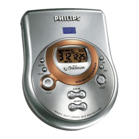
8cm Portable MP3-CD player
TABLE OF CONTENTS
Technical Specification......................................................1-1
Instructions For Use ..................................................1-2...1-6
Service Aids.......................................................................1-7
Handling Chip Components...............................................1-7
Safety & Warnings .............................................................1-8
Service Test Program................................................2-1...2-3
Features List..............................................................2-4...2-5
IC BlockDiagram .......................................................3-1...3-9
BlockDiagram ..................................................................3-10
Printed Circuit Board .................................................4-1...4-2
©
Copyright 2001 Philips Consumer Electronics B.V. Eindhoven, The Netherlands
All rights reserved. No part of this publication may be reproduced, stored in a retrieval
system or transmitted, in any form or by any means, electronic, mechanical, photocopying,
or otherwise without the prior permission of Philips.
Published by YT 0220 Service Audio
Printed in The Netherlands
Subject to modification
Power block...................................................................4-3
CD block........................................................................4-4
CD-Rom block ...............................................................4-5
CPU block .....................................................................4-6
ESP block......................................................................4-7
Audio block....................................................................4-8
Display block .................................................................4-9
Exploded view ...................................................................5-1
Mechanical partslist ...........................................................5-1
Accessories .......................................................................5-1
Electrical partslist ......................................................6-1...6-6
LASER PRODUCT
EXP 411
all versions
CLASS 1
© 3140 785 32100
Advertisement
Table of Contents

Related Manuals for Philips EXP 411


Summary of Contents for Philips EXP 411
-
Page 1: Table Of Contents
LASER PRODUCT © Copyright 2001 Philips Consumer Electronics B.V. Eindhoven, The Netherlands All rights reserved. No part of this publication may be reproduced, stored in a retrieval system or transmitted, in any form or by any means, electronic, mechanical, photocopying, or otherwise without the prior permission of Philips. -
Page 2: Technical Specification
TECHNICAL SPECIFICATIONS General Dimensions (W x H x D) With boxes......................178.0 x 65.0 x 139.0 mm Without boxes....................... 92.0 x 31.5 x 119.5 mm Weight without battery........................188 g Output (CD-DA and MP3) Output level ........................3 mW +1/-2 dB Frequency response.................16 Hz – 20 kHz +/- 3.0 dB (16 ohms) S/N ratio (A-weight) ........................ -
Page 3: Instructions For Use
INSTRUCTIONS FOR USE QUICK START MISE EN SERVICE RAPIDE OPEN HOLD➟OFF PLAY VOLUME CONTROLS (see figure 1) CONTROLS (see figure 1) 1 VOL E ....adjusts the volume % ......type plate 2 LINE OUT/p..3.5 mm line out to connect ^ 4.5V DC ....to connect the external power supply –the headphones –this set to the audio input of your stereo equipment 3 9......stops playback, clears a programme and switches the set off... - Page 4 Visit the homepage PANIUM Mains adapter http://www.expanium.philips.com Only use the AY 3170 mains adapter (4.5 V/300 mA All trademarks used are owned by their respective owners. direct current, positive pole to the center pin). Any other product may damage the set.
- Page 5 INSTRUCTIONS FOR USE BASIC FUNCTIONS POWER SUPPLY/HEADPHONES IMPORTANT! 5 To remove the disc, hold it by its edge and press the hub gently while lifting the disc. • Hearing safety : Do not play your headphones at a high volume. Hearing experts advise that continuous use at high volume can permanently damage Note: After pressing 2;...
- Page 6 INSTRUCTIONS FOR USE FEATURES FEATURES Programming track numbers Storing the last position played-RESUME You can select up to 50 tracks and store them in the memory in a desired You can store the last position played. When restarting, playback continues sequence.
- Page 7 INSTRUCTIONS FOR USE TROUBLESHOOTING TROUBLESHOOTING WARNING: Under no circumstances should you try to repair the set yourself as Prot indication and music file is not played this will invalidate the guarantee. • The music file is protected. Make sure the protection option in your encoder software is deactivated when creating a music file.
-
Page 8: Service Aids
SERVICE AIDS Service T ool: ESD Equipment: Universal Torx driver holder ......4822 395 91019 Anti-static table mat-large Torx bit T10 150mm ........4822 395 50456 1200x650x1.25mm ........4822 466 10953 Torx driver set T6-T20 ......... 4822 395 50145 Anti-static table mat-small Torx driver T10 extended ...... -
Page 9: Safety & Warnings
1 - 8 SAFETY & WARNINGS © ñ WARNING WAARSCHUWING All ICs and many other semiconductors are susceptible to Alle IC´s en vele andere halfgeleiders zijn gevoelig voor electrostatic discharges (ESD). Careless handling during electrostatische ontladingen (ESD). repair can reduce life drastically. Onzorgvuldig behandelen tijdens reparatie kan de levensduur When repairing, make sure that you are connected with the drastisch doen vermindern. -
Page 10: Service Test Program
SERVICE TEST PROGRAM Introduction Purpose: Used for maintenance or to allow the service department to control separately and in a special way the various parts or devices of the set. Inpu ts MODE PROG Keys: Condition: Door must be open in order to enter service mode. Processes Function Service mode... - Page 11 2. Key Test Key Commands Display Min. Play Min. Next Min. Prev Min. Mode Min. rogram Min. Min. ALBUM + Min. ALBUM - Min. Min. Play of Remote control Min. Sec. Stop of Remote control Min. Sec. ext of Remote control Min.
- Page 12 3-1. Motor Test Display Function Next Slide moves outside Image of door SW Image of CDM inner SW (On=0, Off=1) (On=0, Off=1 Prev Slide moves inside Mode Disc motor turns clockwise Stop Exit to main menu Play Enter focus servo test 3-2.
-
Page 13: Features List
FEATURES LIST MP3 Decoder Characteristics MPEG Versions Support [Y/N] MPEG Version 1 (ISO/IEC 11172-3) MPEG Version 2 (ISO/IEC 13818-3) MPEG Version 2.5 (Ext. for low Bitrates) MPEG Layers Support [Y/N] Layer I Layer II Layer III Sample rates [kHz] Support [Y/N] MPEG 1 44.1... - Page 14 Available function Shuffle item Repeat Music Album Repeat Shuffle Repeat Program Track Search Search Search CD type mode mode COMMON 1 COMMON 2 COMMON 3 COMMON 4 (1 PIN) (2 PIN) (3 PIN) (4 PIN) SEGMENT 1 (5 PIN) SEGMENT 2 (6 PIN) SEGMENT 3 (7 PIN)
-
Page 15: Ic Blockdiagram
IC BLOCK DIAGRAMS 7480 : TMS320VC5416 P, C, D, E Buses and Control Signals 64K RAM 64K RAM 16K Program Dual Access 54X cLEAD Single Access Program/Data Data MBus GPIO RHEA TI BUS RHEA Bus Bridge McBSP1 Enhanced XIO McBSP2 McBSP3 16HPI 16 HPI... - Page 16 7850 : SAA7324H/M2B SSA2 DDA2 SSD2 D1 D2 D3 D4 SSA1 DDA1 SSD1 SSD3 DDD1(P) DDD2(C) SYMBOL DESCRIPTION HFREF comparator common mode input HFIN comparator signal input PRE- CONTROL PROCESSING FUNCTION ISLICE current feedback output from data slicer analog ground 1 SSA1 OUTPUT STAGES...
- Page 17 7250 : SC111259AFTA Pin# Symbol Pin Description VIN12 VIN12 SLEEP Sleep input WAKE Wake input OUT1A ERR1 ERR1 Motor Driver Reference Voltage Input(Motor driver) OUT1B ERR4 Control signal input(CH4) SAWTOOTH RSTB Phase correction capacitor connect (CH4) PGND1 Phase correction capacitor connect (CH3) VIN12 ERR3 Control signal input(CH3)
- Page 18 7400 : TMP86CS25F 7400 : TMP86CS25F...
- Page 19 7400 : TMP86CS25F Pin PORT Signals Description 4.233MHz X’tal XOUT TEST TEST Pin DC Supp ly P21 (XTIN) F435 mon itor P22 (XTOUT) MUTE Headpho ne Mute RESET RESET RESET of CPU Active reset Low (PULL UP) P20 (INT5/STOP) DC_IN DC Detect P60 (AIN0) +RCREF...
- Page 20 7800 : SM5903BF YBLKCK Output Interface Input Interface Control YFCLK Input 1 YFLAG YMDATA Input Buffer YMCLK Micro- controller Interface YMLD ZSENSE Compression Through Mode Mode General UC1 to UC5 Port Decoder Encoder YDMUTE Control NRESET Input 2 DRAM Interface NTEST Pin number Pin name...
- Page 21 7481 : MT4LC1M16E5TG-6 DQ15 DQ14 DQ13 DQ12 DQ11 DQ10 CASL# CASH# RAS# NOTE: The "#" symbol indicates signal is active LOW. CASL# DATA-IN BUFFER CAS# CASH# NO. 2 CLOCK DQ15 GENERATOR DATA-OUT BUFFER COLUMN- COLUMN ADDRESS DECODER BUFFER 1,024 REFRESH CONTROLLER SENSE AMPLIFIERS I/O GATING...
- Page 22 V DD 7851 :TZA1024T/N1 7851 :TZA1024T/N1 V DD RGADJ V DD(L) V DD 1× CDRW EQSEL CFIL EQSEL RFFB TZA1024 CDRW 4× RFEQO RFEQO RFFB 2× PWRON CMFB CMFB TZA1024 V GAP RGADJ CFIL V DD PWRON V DD(L) 7350 : BA3574BFS 7851 :TZA1024T/N1 SYMBOL DESCRIPTION...
- Page 23 7482 : M29W400BB70N6T 7482 : M29W400BB70N6T A0-A17 Address Inputs BYTE DQ0-DQ7 Data Inputs/Outputs V SS DQ8-DQ1 Data Inputs/Outputs DQ15A±1 DQ15A±1 Data Input/Output or Address Input DQ14 Chip Enable DQ13 Output Enable Write Enable DQ12 M29W400BB Reset/Block Temporary Unprotect V CC Ready/Busy Output DQ11 BYTE...
-
Page 24: Blockdiagram
3-10 BLOCK DIAGRAM... - Page 25 PRINTED CIRCUIT DIAGRAM 1301 G2 2271 C11 2292 D10 2362 G4 2380 F13 2483 F4 2801 F6 2821 F7 2839 H5 3204 C7 3230 C5 3250 C12 3354 G4 3372 G13 3408 G11 3427 H14 3482 F5 3801 E5 3819 E6 3840 F10 3861 G11 5250 C9...
- Page 26 1300 E12 1302 F12 1501 G5 1502 E7 1503 C5 1504 E6 1505 C4 1506 E7 1507 G4 1508 G4 1509 F6 1510 C4 1511 E3 1512 D4 3501 F3 3502 F7 3503 D6 3504 D6 3505 C5 3506 G5 3507 G5 3508 G4 3509 G5...
-
Page 27: Circuit Diagrams Power Block
CIRCUIT DIAGRAM Power Block 1250 C1 5250 1251 C2 5252 1252 B2 5253 7252 2250 B2 5254 BC869 6252 2251 D3 5256 4.1V 2252 B2 5257 2.7V 2253 D5 5258 SS14 6256 2255 D6 5259 2256 BAT54CW 5257 47uH 2276 2286 2256 A1 5260... -
Page 28: Cd Block
CD Block 1800 D1 F800 A6 1801 B1 F801 B5 2800 C4 F802 A5 CD-RW EXCEPT 3857 3862 Sledge INSW 2801 B5 F803 A6 F800 2.6V +2.6V 2802 C5 F804 A7 3858 3863 Focus +2.6V 7854 BC807-40 2803 A6 F805 E8 LASER ON LASER OFF 3861... -
Page 29: Cd-Rom Block
CD-ROM Block 2480 H2 2481 C2 2482 A3 TMS_RESET 2483 B5 2484 B3 2485 C10 2486 D7 3484 2487 D8 2488 F1 2489 F2 2482 DSP_CLK 100n 2490 F4 2491 D2 2492 F3 2493 D2 2494 F5 2495 C7 2496 D6 +core +3.3V +3.3V... -
Page 30: Cpu Block
CPU Block 1400 E7 1401 F6 F430 F428 F426 F424 F422 F420 F418 F416 F414 F412 F410 F408 F406 F402 3432 F431 F429 F427 F425 F423 F421 F419 F417 F415 F413 F411 F409 F407 +2.6V 100k +2.6V 1402 A6 MP3 0V/CDDA 2.6V +2.6V 2400 E2 3433... -
Page 31: Esp Block
ESP Block 2860 C3 2861 D6 2862 E5 2863 B3 2864 B5 2865 E5 2866 E4 2867 B5 3880 C3 26 25 24 23 22 21 19 18 17 16 15 14 3881 D6 3882 D6 3883 B5 3884 E4 SBSY 3885 E4 SBSY... -
Page 32: Audio Block
AUDIO Block 1300 F8 1301 F4 1302 G5 2351 D5 2352 C4 2353 D4 2354 D4 2355 D4 2356 D3 2357 C3 2358 D2 2359 D2 2360 D3 2361 D2 2362 C3 2363 D7 2364 D6 2365 D5 2366 D6 2367 D8 DBB OFF DBB1... -
Page 33: Display Block
Display Block 1501 B3 1502 C3 1503 D3 1504 F3 1505 G3 1506 B2 1507 C2 1508 D2 1509 F2 1510 G2 +A VDD +A VDD 1511 G5 1512 C8 3501 B3 3502 C3 3503 D3 3506 3501 3504 E3 3505 G3 SPEC.for KEY-SENSE 3506 B1... -
Page 34: Exploded View
EXPLODED VIEWS MECHANICAL PARTS LIST 3140 117 63730 CD DOOR ASSY - EXP411 3140 117 61670 CABINET ASSY /00/01 3140 117 63900 BOTTOM ASSY - EXP411/00 3140 117 63740 BOTTOM ASSY - EXP411/17 203-1 4822 462 41819 RUBBER 3140 111 21950 BASE PLATE (PCB COVER) 3140 111 01090 SPRING TOP CASE (DOOR SPRING) -
Page 35: Electrical Partslist
ELECTRICAL PARTSLIST - MAIN BOARD - MISCELLANEOUS - - CAPACITORS - 1250 8240 005 55800 DC SUPPLY SOCKET 2353 5322 126 11582 6,8nF10% X7R 63V 1301 2422 025 17393 CONNECTOR 11P FPC 2354 2020 552 96305 4,7µF +80-20% Y5V 10V 1400 8240 009 50030 SWITCH-SLIDE 1P 3POS... - Page 36 ELECTRICAL PARTSLIST - MAIN BOARD - CAPACITORS - - CAPACITORS - 2489 4822 126 14305 100nF 10% X7R 16V 2841 5322 126 11579 3,3nF 10% X7R 63V 2490 4822 126 14305 100nF 10% X7R 16V 2842 5322 126 11579 3,3nF 10% X7R 63V 2491 4822 126 14305 100nF 10% X7R 16V...
- Page 37 ELECTRICAL PARTSLIST - MAIN BOARD - RESISTORS - - RESISTORS - 3253 4822 051 30472 4,7K 5% 0,062W 3408 4822 051 30272 2,7K 5% 0,062W 3255 4822 117 13632 100K 1% 0,62W 3410 4822 051 30102 1K 5% 0,062W 3256 4822 051 30103 10K 5% 0,062W 3411...
- Page 38 ELECTRICAL PARTSLIST - MAIN BOARD - RESISTORS - - RESISTORS - 3498 4822 117 12971 15R 5% 0,62W 3854 4822 051 30103 10K 5% 0,062W 3499 4822 051 30101 100R 5% 0,062W 3855 4822 051 30103 10K 5% 0,062W 3800 4822 051 30332 3,3K 5% 0,062W 3856...
- Page 39 ELECTRICAL PARTSLIST - MAIN BOARD - DIODES - - IC & TRANSISTORS - 6252 9322 128 70685 SS14 7408 3198 010 42310 BC847BW 6253 4822 130 11397 BAS316 7480 9322 170 91671 TMS320DA150PGE160 6254 4822 130 11397 BAS316 7481 9322 142 92668 MT4LC1M16E5TG-6 6256 9340 289 00115...
- Page 40 ELECTRICAL PARTSLIST - DISPLAY BOARD - MISCELLANEOUS - 1300 8240 005 52310 HEADPHOE SOCKET 1302 2422 025 17394 CONNECTOR 11P FPC 1501 2422 128 03013 SWITCH-TACT 1502 2422 128 03013 SWITCH-TACT 1503 2422 128 03013 SWITCH-TACT 1504 2422 128 03013 SWITCH-TACT 1505 2422 128 03013...