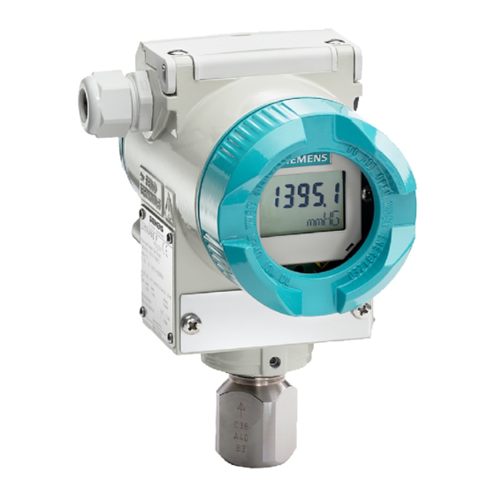
Summary of Contents for Siemens 7MF4033
- Page 1 INSTALLATION GUIDE Siemens Industry, Inc. IGSITRPDS3-1 Rev 5 February 2012 SITRANS P, Series DSIII Transmitters Pressure, Differential Pressure, Flanged Level, and Absolute Pressure Model 7MF4*33-...
-
Page 2: Table Of Contents
Siemens Industry, Inc. assumes no liability for errors or omissions in this document or for the application and use of information in this document. The information herein is subject to change without notice. -
Page 3: February 2012
DSIII for Pressure Differential Pressure, Flanged Level and Absolute Pressure Model 7MF4*33-….). The manual is supplied on the Siemens Process Instrumentation User Manual CD, included with a Series DSIII transmitter shipment. The current version of the User’s Manual, in Portable Document Format (PDF) can also be downloaded at the Siemens public Internet site. -
Page 4: Introduction
User’s Manual UMSITRPDS3-1. Detailed product specifications are also included in the User’s Manual. The User’s Manual is supplied on the Siemens Process Instrumentation User Manual CD, included with a Series DSIII transmitter shipment. To access UMSITRPDS3-1 on the supplied Siemens Process Instrumentation User Manual CD, perform the brief procedure below. -
Page 5: Gauge Construction, Pressure And Absolute Pressure Models
Enclosure rotation limits Electronics module and display; remove Enclosure rotation reference arrow; see the enclosure cap for access Installation section for details This Figure is for Models 7MF4033 and 7MF4233 FIGURE 1 Gauge Construction, Pressure and Absolute Pressure Models February 2012... -
Page 6: Differential Construction; Differential, Flow, And Absolute Models
Installation Guide UMSITRPDS3-1 Process Connection 1/4-18NPT for absolute Side vent for measuring gas (supplement H02) pressure + side Mounting bracket, optional Mounting thread M10, M12 or 7/16-20UNF Enclosure setscrew Blanking plug Enclosure rotation limits (see 14 reference Electrical connection: arrow) Screwed gland M20 x 1.5 Enclosure rotation reference arrow;... -
Page 7: Differential Pressure And Flow Models With H03 Option
IGSITRPDS3-1 Installation Guide Process connection 1/4-18NPT Blanking plug Mounting thread M10 or 7/16-20UMF Access cover over magnetic pushbuttons Field terminals; remove enclosure cap for Electrical connection: access M20 x 1.5 Electronics module and display; remove 1/2-14NPT enclosure cap for access Tag plate Sealing screw Approval plate;... -
Page 8: Flanged Liquid Level Models
Installation Guide UMSITRPDS3-1 Process connection at low side 1/4-18NPT Access cover to magnetic pushbuttons Mounting thread M10, M12, or 7/16-20UNF Sealing screw with vent shown (optional) Blanking plug Enclosure setscrew Electrical connection: Enclosure rotation limits M20 x 1.5 Enclosure rotation reference arrow (not 1/2-14NPT shown;... -
Page 9: Rating, Approval, And Tag Plates
IGSITRPDS3-1 Installation Guide Shown below are the transmitter display and the field (signal) terminals, located at opposite ends of the enclosure. The transmitter enclosure and the display can be rotated for ease of reading regardless of transmitter orientation. An enclosure ground connection is located on the housing beneath the field terminal enclosure cap. The enclosure should always be grounded by a wire connected from this terminal to an earth ground, even when a ground may be provided by metal conduit protecting the loop wiring. -
Page 10: Customer/Product Support
Read and complete the Siemens RMA form(s). For support and the location of your local Siemens representative, refer to the table below for the URL of the Process Instrumentation (PI) portion of the Siemens public Internet site. Once at the site, click Support in the right column and then Product Support. -
Page 11: Installation
IGSITRPDS3-1 Installation Guide INSTALLATION Transmitter mechanical and electrical installation is outlined in this section. IMPORTANT Before installing or servicing the transmitter: • Read the information on the transmitter’s rating and approval plates and ensure that the correct model is at hand and that the correct procedures in this guide and User’s Manual UMSITRPDS3-1 are followed. -
Page 12: Standard Pmc-Style Process Connection
3. Position Tack Weld 4. Fillet Weld FIGURE 10 Nipple Installation Other process connections are available, including a PMC-style minibolt weldable socket version (flush front construction). Refer to the Siemens Process Automation catalog: Field Instruments for Process Automation. February 2012... -
Page 13: Enclosure Rotation
IGSITRPDS3-1 Installation Guide 3. Remove the nipple from the transmitter by unscrewing the lock-ring nut on the transmitter. Save the thin, white Teflon gasket. 4. Screw the dummy plug into the nipple. See Figure 11. 1. Nipple 2. PMC Dummy Plug 3. -
Page 14: Display Orientation
Installation Guide UMSITRPDS3-1 Differential Construction Gauge Construction Enclosure rotation arrow (enclosure rotation reference point) Ramp-shaped recessed area indicating enclosure rotation range; maximum rotation of the enclosure is approximately 135º either direction from the point where the enclosure rotation arrow points directly at the enclosure setscrew. Enclosure setscrew (use a 3/32"... -
Page 15: Electrical Conduit And Cable Installation
IGSITRPDS3-1 Installation Guide 1. Display Mounting Screw 2. Display Assembly 3. Enclosure Setscrew Note: Shown with enclosure cap with sightglass removed. FIGURE 14 Display Removal and Repositioning Electrical Conduit and Cable Installation Figure 15 shows conduit connections. Electrical conduit and wiring is supplied by the user. Field terminals are shown in Figure 6. -
Page 16: Electrical Installation
Installation Guide UMSITRPDS3-1 Electrical Installation This section outlines loop wiring for Point-to-Point and Multi-Drop networks. Refer to User’s Manual UMSITRPDS3-1, Section 4 Installation for wiring diagrams and for installation in a hazardous area. WARNING Hazardous voltage can cause death or serious injury. Remove power from all wires and terminals before working on this equipment.


