Table of Contents
Advertisement
Advertisement
Table of Contents
Troubleshooting

Related Manuals for HP J9979A


Summary of Contents for HP J9979A
- Page 1 HP 1820 Switch Series Installation and Getting Started Guide HP 1820-8G Switch (J9979A) HP 1820-24G Switch (J9980A) HP 1820-48G Switch (J9981A) HP 1820-8G-PoE+ (65W) Switch (J9982A) HP 1820-24G-PoE+ (185W) Switch (J9983A) HP 1820-48G-PoE+ (370W) Switch (J9984A) Power over Ethernet...
- Page 3 HP 1820 Switch Series Installation and Getting Started Guide...
- Page 4 The only warranties for HP products and services are set forth in the express warranty statements accompanying such products and services. Nothing herein should be construed as constituting an additional warranty. HP shall not be liable for technical or editorial errors or omissions contained herein.
-
Page 5: Table Of Contents
Contents 1 Switch Overview Switch Hardware Features ........1-2 Network Ports . - Page 6 HP Customer Support Services ........4-6...
-
Page 7: Switch Overview
Switch Overview The HP 1820 Switch Series are multiport switches that can be used to build high-performance switched workgroup networks. These switches are store- and-forward devices that offer low latency for high-speed networking. Three of the switches also support the IEEE 802.3at standard for providing PoE+ power to connected devices. -
Page 8: Switch Hardware Features
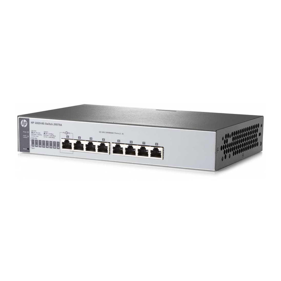
Switch Overview Switch Hardware Features Switch Hardware Features HP 1820-8G Switch (J9979A) PoE PD port Power and Fault/ Locator LEDs Reset button 10/100/1000BASE-T RJ-45 ports Link/Act and Speed LEDs HP 1820-24G Switch (J9980A) Link/Act and Speed LEDs Power and Fault/... - Page 9 Switch Overview Switch Hardware Features HP 1820-8G-PoE+ (65W) Switch (J9982A) PoE+ ports 1-4 Link/Act and Mode LEDs Power and Fault/ Locator LEDs Mode button Reset button 10/100/1000BASE-T RJ-45 ports HP 1820-24G-PoE+ (185W) Switch (J9983A) PoE+ ports 1-12 Power and Fault/...
-
Page 10: Network Ports
IP telephones, wireless LAN Access Points, and other appliances to receive power as well as data over existing LAN cabling. For further information regarding PoE power, see the HP Power over Ethernet (PoE/ PoE+) Planning and Implementation Guide, which is on the HP Web site www.hp.com/support/manuals. ■... -
Page 11: Leds
** The blinking behavior is a 2 second on/off cycle; 1 second on, 1 second off. *** The blinking behavior is a 4 second on/off cycle; 3 seconds on, 1 second off. ‡ (HP 1820 PoE+ switches only) Press the Mode button in for PoE mode, leave the Mode button out for Spd mode. -
Page 12: Mode Button
Switch Hardware Features Mode Button The HP 1820 PoE+ switches have one Mode LED per port. The Mode LED shows either the port speed or the PoE status. In PoE mode, it shows whether the port is configured to provide PoE power. The operation of the Mode LED is controlled by the Mode select button. -
Page 13: Switch Features
The features of the HP 1820 Switches include: 8, 24, or 48 auto-sensing 10/100/1000BASE-T RJ-45 ports. ■ ■ 2 or 4 SFP slots for HP SFP transceivers (1820-24G, 1820-24G-PoE+, 1820- 48G, and 1820-48G-PoE+ Switches only) plug-and-play networking—all ports are enabled—just connect the ■... - Page 14 Switch Overview Switch Features...
-
Page 15: Installing The Switch
Installing the Switch The HP 1820 Switches are easy to install. They come with an accessory kit that includes the brackets for mounting the switches in a standard 19-inch telco rack, in an equipment cabinet, and with rubber feet that can be attached so the switches can be securely located on a horizontal surface. - Page 16 Switzerland 8120-6807 8120-5339 South Africa 8121-0919 8120-5341 South Korea 8120-6811 8120-5336 Taiwan 8121-0964 8121-0967 Thailand 8121-0673 8121-0671 UK/Hong Kong/Singapore/Malaysia 8120-6809 8120-5334 US/Canada/Mexico 8120-6805 8121-0973 The cord for the HP 1820-48G-PoE+ Switch supports a higher amperage and uses a C16 connector.
- Page 17 Installing the Switch Included Parts The 1820-8G external AC/DC power adapters, one of the following: ■ • Universal Inline AC/DC Power Adapter All countries/regions 5066-1122 Power Cords for Inline AC/DC Power Adapter Australia/New Zealand 8121-0870 Thailand 8121-0664 China 8120-8373 India 8121-0702 Israel 8120-6314...
-
Page 18: Installation Precautions
Use only the AC/DC power adapter and power cord (if applicable), supplied with the switch. Use of other adapters or power cords, including those that came with other HP Networking products, may result in damage to the equipment. For those switches that use a power cord, if your installation requires a... -
Page 19: Installation Procedure
19-inch telco rack, in an equipment cabinet, on a wall, under a table, or on a horizontal surface. The HP 1820 8-port switches can be mounted on a wall, under a table, or on a horizontal surface. -
Page 20: Prepare The Installation Site
Before mounting the switch, verify it is working properly by plugging it into a power source and confirming that it passes self test. For the HP 1820 24- and 48-port switches, connect the power cord supplied with the switch to the power connector on the back of the switch, and then into a properly grounded electrical outlet. - Page 21 AC power outlet N o t e The HP 1820 24- and 48-port switches do not have a power switch. They are powered on when the power cord is connected to the switch and to a power source.
- Page 22 Installing the Switch Installation Procedure The HP 1820 8-port switches also do not have a power switch. They are powered on when the external AC/DC power adapter is connected to the switch and the adapter power cord to a power source. The external AC/DC power adapter automatically adjusts to any voltage between 100-240 volts and either 50 or 60 Hz.
-
Page 23: Mount The Switch
Installing the Switch Installation Procedure • The Fault/Locator LED turns off when the self test completes. When the self test completes successfully: • The Power LED remains on. The Fault/Locator LED stays off. • • The port LEDs on the front of the switch go into their normal opera- tional mode: If the ports are connected to active network devices, the Link/Act –... - Page 24 Installing the Switch Installation Procedure E q u i p m e n t The screws supplied with the switch are the correct threading for standard C a b i n e t EIA/TIA open 19-inch racks. If you are installing the switch in an equipment cabinet such as a server cabinet, use the clips and screws that came with the N o t e cabinet in place of the screws that are supplied with the switch.
- Page 25 Installing the Switch Installation Procedure Wall or Under-TableMounting You can mount the HP 1820 24- and 48-port switches on a wall with either the front or rear panel facing up. W A R N I N G For safe operation, please read the “Installation Precautions” on page 2-4 before mounting the switch.
- Page 26 Installing the Switch Installation Procedure Wall anchors are included in the accessory kit for use with plastered brick or concrete walls. Wall anchors 20-mm M4 tap screws For under-table mounting, a third 20-mm M4 tap screw can be placed against one side of the switch to secure it in place. Horizontal Surface Mounting Place the switch on a table or other horizontal surface.
-
Page 27: Connect The Switch To A Power Source
MicroSaver security cable (not included) to attach the switch to an immovable object. 4. Connect the Switch to a Power Source For the HP 1820 24-port and 48-port switches, plug the included power cord into the switch’s power connector and into a nearby AC power source. -
Page 28: Connect The Network Cables
Installation Procedure 2.) Re-check the LEDs during self test. See “Self Test LED Behavior” on page 2-8. For the HP 1820 8-port switches, use the included cable tie to secure the power cord to the switch. 5. Connect the Network Cables... -
Page 29: Installing Or Removing Sfps
SFP. C a u t i o n Use only supported genuine HP SFPs with your switch. Non-HP SFPs are not supported, and their use may result in product malfunction. Should you require additional HP SFPs, contact your HP Networking Sales and Service Office or authorized dealer. - Page 30 You should disconnect the network cable from the SFP before removing it from the switch. Depending on when you purchased your HP SFP, it may have either of three different release mechanisms: a plastic tab on the bottom of the SFP, a plastic collar around the SFP, or a wire bail.
-
Page 31: Configuring The Switch
Configuring the Switch Initial Configuration The HP 1820 Switch Series can be managed through a Web-browser interface that you can access from any PC or workstation connected to the switch. To access the Web interface, you must have the switch’s Internet Protocol (IP) address. - Page 32 See the HP 1820 Switch Series Management and Configuration Guide for more switch configuration information. N o t e If you cannot remember the switch’s IP address or password, you can restore...
-
Page 33: Using The 192.168.1.1 Ip Address
Configuring the Switch Using the 192.168.1.1 IP Address Using the 192.168.1.1 IP Address If the switch does not acquire an IP address via the DHCP request, it defaults to the following configuration: Parameter Factory Default Setting Password <blank> IP address 192.168.1.1 Subnet mask 255.255.255.0... -
Page 34: Where To Go From Here
Where to Go From Here For more information on the Web browser interface and all the features that can be configured on the HP 1820 Switch Series, see the HP 1820 Switch Series Management and Configuration Guide, which is available on the HP Web site, http://www.hp.com/support/manuals... -
Page 35: Troubleshooting
Troubleshooting This section describes how to troubleshoot the switch. For more information, see the chapter “Troubleshooting” in the HP 1820 Switch Series Management and Configuration Guide, available on the HP Web site, http://www.hp.com/support/manuals. This chapter describes the following: ■ basic troubleshooting tips... -
Page 36: Diagnosing With The Leds
Troubleshooting Diagnosing with the LEDs Diagnosing with the LEDs The first section shows LED patterns on the switch that indicate problem conditions for general switch operation troubleshooting. The second section shows LED patterns that indicate problem conditions for PoE troubleshooting. LED patterns for General Switch Troubleshooting Check in the table below for the LED pattern you see on your switch. -
Page 37: Diagnostic Tips
Try power cycling the switch. If the fault indication reoccurs, the switch port may which the Link LED is have failed. To confirm, try a different port that appears to be good. Call your HP- blinking has authorized network reseller, or use the electronic support services from HP to get experienced a self test assistance. -
Page 38: Led Patterns For Poe Troubleshooting
Troubleshooting Diagnosing with the LEDs LED Patterns for PoE Troubleshooting Press the LED Mode button to put the switch into PoE mode and the port Mode LEDs will show which ports are experiencing the problem. The following tables identify the specific problems that are shown by the LEDs. Check in the table for the LED pattern you see on your switch. -
Page 39: Testing The Switch By Resetting It
Troubleshooting Testing the Switch by Resetting It Testing the Switch by Resetting It If you believe the switch is not operating correctly, you can reset the switch to test its circuitry and operating code. To reset the switch, unplug and plug in the power cord (power cycling). -
Page 40: Hp Customer Support Services
Additionally, your HP authorized network reseller can provide you with assistance, both with services they offer and with services offered by HP. Before Calling Support Before calling your networking dealer or HP Support, to make the support... -
Page 41: Switch Specifications
Specifications Switch Specifications Physical Width Depth Height Weight 1820-8G (J9979A) 25.4 cm (10.0 in) 15.95 cm (6.28 in) 4.4 cm (1.73 in) 0.8 kg (1.8 lb) 1820-24G (J9980A) 44.25 cm (17.42 in) 24.61 cm (9.69 in) 4.4 cm (1.73 in) 2.7 kg (6.0 lb) -
Page 42: Environmental
Specifications Switch Specifications The switch automatically adjusts to any voltage between 100-127 or 200-240 volts and either 50 or 60 Hz. The switch can also be powered by a PoE PD connection to Port 1. Port 1 is an IEEE 802.3af Compatible PD (PoE Powered Device) - Class 3. Environmental Operating Non-Operating... -
Page 43: Standards
Specifications Standards Standards Laser safety information Technology Compatible with these EN/IEC standard SFP Lasers IEEE standards compliance 10-T IEEE 802.3 10BASE-T 100-TX IEEE 802.3u 100BASE-TX 1000-T IEEE 802.3ab 1000BASE-T 100-FX IEEE 802.3u 100BASE-FX EN/IEC 60825 Class 1 Laser Product Laser Klasse 1 1000-SX IEEE 802.3z 1000BASE-SX EN/IEC 60825... -
Page 44: Cabling And Technology Information Specifications
Specifications Cabling and Technology Information Specifications Cabling and Technology Information Specifications 10 Mbps Operation Category 3, 4 or 5, 100-ohm unshielded twisted-pair (UTP) or shielded twisted-pair (STP) cable, complying with IEEE 802.3 10BASE-T specifications. 100 Mbps Operation Category 5, 100-ohm UTP or STP cable, complying with IEEE Twisted-pair copper 802.3u 100BASE-TX specifications. -
Page 45: Technology Distance Specifications
Specifications Mode Conditioning Patch Cord Technology Distance Specifications Technology Supported cable type Multimode fiber Supported distances modal bandwidth 100-FX multimode fiber up to 2,000 meters 1000-T twisted-pair copper up to 100 meters 1000-SX multimode fiber 160 MHz*km 2 - 220 meters 200 MHz*km 2 - 275 meters 400 MHz*km... -
Page 46: Installing The Patch Cord
Specifications Mode Conditioning Patch Cord N o t e Most of the time, if you are using good quality graded-index multimode fiber cable that adheres to the standards listed in this appendix, there should not be a need to use mode conditioning patch cords in your network. This is especially true if the fiber runs in your network are relatively short. -
Page 47: Twisted-Pair Cable/Connector Pin-Outs
Specifications Twisted-Pair Cable/Connector Pin-Outs Twisted-Pair Cable/Connector Pin-Outs The Auto-MDIX Feature: In the default configuration, “Auto”, the fixed 10/ 100/1000BASE-T ports on the switches all automatically detect the type of port on the connected device and operate as either an MDI or MDI-X port, whichever is appropriate. - Page 48 Specifications Twisted-Pair Cable/Connector Pin-Outs For 100 Mbps connections to the ports, use 100-ohm Category 5 UTP or ■ STP cable only, as supported by the IEEE 802.3u Type 100BASE-TX standard. ■ For 1000 Mbps connections, 100-ohm Category 5e or better cabling is recommended.
-
Page 49: Straight-Through Twisted-Pair Cable For 10 Mbps Or 100 Mbps Network Connections
Specifications Twisted-Pair Cable/Connector Pin-Outs Straight-through Twisted-Pair Cable for 10 Mbps or 100 Mbps Network Connections Because of the Auto-MDIX operation of the 10/100 ports on the switch, for all network connections, to PCs, servers or other end nodes, or to hubs or other switches, you can use straight-through cables. -
Page 50: Crossover Twisted-Pair Cable For 10 Mbps Or 100 Mbps Network Connection
Specifications Twisted-Pair Cable/Connector Pin-Outs Crossover Twisted-Pair Cable for 10 Mbps or 100 Mbps Network Connection The Auto-MDIX operation of the 10/100 ports on the switch also allows you to use crossover cables for all network connections, to PCs, servers or other end nodes, or to hubs or other switches. -
Page 51: Straight-Through Twisted-Pair Cable For 1000 Mbps Network Connections
Specifications Twisted-Pair Cable/Connector Pin-Outs Straight-Through Twisted-Pair Cable for 1000 Mbps Network Connections 1000BASE-T connections require that all four pairs of wires be connected. Cable Diagram N o t e Pins 1 and 2 on connector “A” must be wired as a twisted pair to pins 1 and 2 on connector “B”. - Page 52 Specifications Twisted-Pair Cable/Connector Pin-Outs A-12...
-
Page 53: B Emc Regulatory Statements
EMC Regulatory Statements Regulatory Statements U.S.A. FCC Class A This equipment has been tested and found to comply with the limits for a Class A digital device, pursuant to part 15 of the FCC Rules. These limits are designed to provide reasonable protection against harmful interference when the equipment is operated in a commercial environment. - Page 54 EMC Regulatory Statements Regulatory Statements Japan VCCI Class A Korea Taiwan...
- Page 55 … 1-2 cross-over cable acoustic specifications … A-2 pin-out … A-10 auto MDI/MDI-X operation … A-9, A-11 HP Auto-MDIX feature … A-7 description front of switch … 1-2 back of switch LEDs … 1-5 power connector … 1-6 switch …...
- Page 56 10/100BASE-TX, location on switch … 1-2–1-3 10/100Base-TX, location on switch … 1-2–1-3 connecting to … 2-14–2-15 LEDs HP Auto-MDIX feature … A-7 behavior during self test … 2-8 network connections … 2-14–2-15 descriptions of … 1-5 power connector … 1-6 error indications …...
- Page 57 … A-10 pin-outs … A-7, A-9, A-11 straight-through cable pin-out … A-9, A-11 switch-to-computer connection … A-9, A-11 switch-to-switch or hub connection … A-10 twisted-pair ports HP Auto-MDIX feature … A-7 wiring rules for twisted-pair cables … A-7 Index-3...
- Page 58 Index-4...
- Page 59 © Copyright 2015 Hewlett-Packard Development Company, L.P. The information contained herein is subject to change without notice. The only warranties for HP products and services are set forth in the express warranty statements accompanying such products and services. Nothing herein should be construed as constituting an additional warranty.