Philips AZ1060 Service Manual
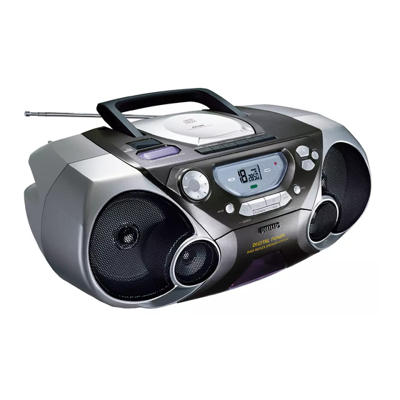
Cd stereo radio recorder
Hide thumbs
Also See for AZ1060:
- User manual (52 pages) ,
- Specifications (2 pages) ,
- User manual (44 pages)
Table of Contents
Advertisement
Quick Links
CD Stereo Radio Recorder
TABLE OF CONTENTS
Handling chip components and safety
Technical Specification & Service Tools
..................................................
................................................
.................................................
...................................................
........................................
.............................................................
...........................................................
.......................................................
.......................................................
...................................................
circuit diagram
.......................................................
POWER BOARD
.......................................................
circuit diagram
.......................................................
layout diagram
Safety regulations require that the set be restored to its original
condition and that parts which are identical with those specified
be used.
C
Copyright 1995 Philips Consumer Electroncis B.V. Eindhoven, The Netherlands
All rights reserved. No part of this publication may be reproduced, stored in a retrieval
system or transmitted, in any form or by any means, electronic, mechanical, photocopying,
or otherwise without the prior permission of Philips.
Published by SS 0047 Service Audio
PCS 107 111
chapter
.............................
1 - 1
..........................
2 - 1
2 - 2
3 - 1
4 - 1
5 - 1
5 - 2
6 - 1
6 - 2
7 - 1, 7 - 3
7 - 2
8 - 1
8 - 1
Printed in The Netherlands
.......................................................
circuit diagram
.......................................................
layout diagram
REOCRDER BOARD
.......................................................
circuit diagram
.......................................................
layout diagram
CD MODULE
.......................................................
circuit diagram
.......................................................
layout diagram
EXPLODED VIEWS DIAGRAM
.................................................................
cabinet
............................................................
.....................................................
...............................................
Electrical partslist
Copyright reserved
Subject to modification
AZ1060
AZ1065
all versions
chapter
9 - 1
9 - 2
10 - 1
10 - 2
11 - 2
11 - 1
12 - 1
12 - 2
12 - 2
13 - 1 to 13 - 8
CLASS 1
LASER PRODUCT
3140 785 22530
GB
Advertisement
Table of Contents

Related Manuals for Philips AZ1060


Summary of Contents for Philips AZ1060
-
Page 1: Table Of Contents
LASER PRODUCT Copyright 1995 Philips Consumer Electroncis B.V. Eindhoven, The Netherlands All rights reserved. No part of this publication may be reproduced, stored in a retrieval system or transmitted, in any form or by any means, electronic, mechanical, photocopying, or otherwise without the prior permission of Philips. - Page 2 1 - 1 HANDLING CHIP COMPONENTS © ñ WARNING WAARSCHUWING All ICs and many other semiconductors are susceptible to Alle IC´s en vele andere halfgeleiders zijn gevoelig voor electrostatic discharges (ESD). Careless handling during electrostatische ontladingen (ESD). repair can reduce life drastically. Onzorgvuldig behandelen tijdens reparatie kan de levensduur When repairing, make sure that you are connected with the drastisch doen vermindern.
-
Page 3: Technical Specifications
TECHNICAL SPECIFICATIONS TUNER - AM SECTION GENERAL Tuning range MW : 531 - 1602 kHz Mains voltage -/00/05/14 : 230 V -/17 : 530 - 1700 kHz -/01/11/16 : 120 / 230 V LW : 153 – 279 kHz -/17 : 120 V IF frequency : 468 kHz ±... -
Page 4: Service Measurement
SERVICE MEASUREMENT Tuner FW Bandpass LF Voltmeter 250Hz-15kHz e.g. PM2534 e.g. 7122 707 48001 RF Generator e.g. PM5326 S/N and distortion meter e.g. Sound Technology ST1700B Use a bandpass filter to eliminate hum (50Hz, 100Hz) and disturbance from the pilottone (19kHz, 38kHz). Tuner AM (MW,LW) Bandpass LF Voltmeter... -
Page 5: Connections & Controls
CONNECTIONS AND CONTROLS PCS 107 113... -
Page 6: Instructions For Use
INSTRUCTIONS FOR USE PCS 107 114... - Page 7 INSTRUCTIONS FOR USE PCS 107 115...
- Page 8 INSTRUCTIONS FOR USE PCS 107 116...
- Page 9 INSTRUCTONS FOR USE PCS 107 117...
- Page 10 INSTRUCTIONS FOR USE PCS 107 118...
- Page 11 DISASSEMBLY DIAGRM A. To remove Top Cabinet Assy B. To remove AF Board C. To remove Rear Cabinet D. To remove Tape Deck E. To remove Front Panel Assy F. To remove Front Board G. To remove Volume Board PCS 107 119...
-
Page 12: Cd Service Test Program
CD SERVICE TEST PROGRAM To enter Service CD TEST TUNER TEST To enter Service Testprogramm hold Testprogramm hold PLAY & STOP buttons PLAY & STOP buttons STOP button pressed in any step returns depressed while switching depressed while switching to begin of Service Testprogram. CD mode on. - Page 13 Abbreviations and Pin-description of CD Ics Abbreviations and Pin-description of CD Ics SERVO PROCESSOR SAA7325H SERVO PROCESSOR SAA7325H SYMBOL DESCRIPTION SYMBOL DESCRIPTION HFREF comparator common mode input microcontroller interface R/W and load control line input (4-wire bus mode) HFIN comparator signal input SILD microcontroller interface R/W and load control line input (4-wire bus mode) ISLICE...
-
Page 14: Block Diagram
4 OHM POWER UP/DOWN VOLUME To mp 6 AMPLIFIER (AZ1065 ONLY) CD - 99 (FOR AZ1065) CD MODULE Tuner (Volume Board) ROTARY VOLUME (FOR AZ1060) +Tuner V.M. (AZ1060 ONLY) To mp Vcc2 ECO6 TUNER MODULE To Tuner Transformer MUTE To CD... -
Page 15: Wiring Diagram
WIRING DIAGRAM FRONT BOARD CD99 /DA11 AUDIO BOARD CD99MB /DA11 ECO-6-PA SECONDARY CD DOOR LATCH SWITCH POWER BOARD ECO-MTF-PA-SD-MS (FE) PRIMARY PRIMARY (for non /01 /11 /16) (for /01 /11 /16) PCS 107 121... -
Page 16: Front Board Circuit Diagram
3459 3465 3451 3480 3481 4498 4499 7407 P = PROVISIONAL MODEL TUNER MODE # = FOR AZ1060 (non RC + ROT VOL) AZ1060 CD MODE * = FOR AZ1065 (RC + UP/DN VOL) 100n 100n 100p 470p 470R AZ1065... -
Page 17: Layout Diagram
50KBX2 L-TOP T503 T504 R-TOP T505 AF BOARD R-TAP T506 R-VC T507 T508 L-VC FE-ST-VK-N FOR AZ1060 ONLY 1488 T509 3487 T510 FRONT BOARD 1503 VOLUME 1504 VOLUME EH-S DOWN FOR AZ1065 ONLY VOLUME BOARD - LAYOUT DIAGRAM PCS 107 123... -
Page 18: Af Board
AF BOARD (AZ1060) - CIRCUIT DIAGRAM T11 B1 T22 D1 T30 G1 T42 E13 T51 F13 T59 D13 T76 C10 1301-D G5 1502 D1 2309 B1 2345 B12 2353 D11 2363 G2 2508 C5 2522 C6 2530 D8 3303 B11... -
Page 19: Layout Diagram
AF BOARD - LAYOUT DIAGRAM PCS 107 125... - Page 20 AF BOARD (AZ1065) - CIRCUIT DIAGRAM T11 B1 T22 D1 T30 G1 T42 E13 T51 F13 T59 D13 T76 C10 1301-D G5 1502 D1 2338 D10 2347 B12 2357 C10 2503 B4 2515 A4 2525 B7 2533 B9 3306 D11 3323 H9 3333 F11 3508 G3...
- Page 21 POWER BOARD - CIRCUIT & LAYOUT DIAGRAM F01 C1 F02 C1 Mains F03 B3 Supply F04 B3 POWER TRANSFORMER C-PAD VOLTAGE SELECTOR 0001 AC INLET F05 D9 9001 1012 F06 B9 F07 B10 110V SET POWER CORD F08 C8 9004 0001 A7 1011 Mains...
- Page 22 TUNER BOARD ECO6 - CIRCUIT DIAGRAM 1105 A1 5114 B11 1121 F14 5119 G9 1122 E14 5121 E11 TUNER BOARD ECO6 / PORTABLE AUDIO 2101 A3 5122 H5 2103 C7 5123 G5 AM-IF1 VERSION PROGRAMMING COMPONENTS 2104 A3 5130 E6 5111 450kHz 2106 B4...
-
Page 23: Tuner Board
TUNER BOARD ECO6 - LAYOUT DIAGRAM TUNER ADJUSTMENT TABLE ( ECO6 FM/MW- and FM/MW/LW - versions with AM-frame aerial ) Waverange Input frequency Input Tuned to Adjust Output Scope/Voltmeter 1105 B7 2106 D6 2129 C5 2155 C5 2191 A2 5102 D7 5110 B3 5114 B3 5122 B6... - Page 24 10-1 10-1 RECORDER BOARD - CIRCUIT DIAGRAM 1707 C 3 1709 A14 2706 B 4 2711 F 6 2719 C 8 2727 F 7 2733 H13 2750 D 6 3703 D 3 3712 E 7 3720 F 7 3730 F12 3743 C 9 3761 G 6 7705 G 4...
- Page 25 10-2 10-2 RECORDER BOARD - LAYOUT DIAGRAM 71 A 1 2729 C 5 3733 B 2 9756 C 3 72 D 5 2730 D 1 3734 D 5 9757 D 3 73 A 5 2731 C 1 3735 D 3 9759 D 4 74 A 1 2732 B 1...
- Page 26 11-1 11-1 CD99 DA11 - LAYOUT DIAGRAM 1800 3703 3876 CD99 Board component side view CD99 Board copper side view 1801 3704 3877 1810 3705 3878 1821 3728 3879 1822 3745 3880 2840 5802 1823 3750 3881 1824 3751 3882 2701 3757 3883...
- Page 27 11-2 11-2 11-2 CD99 DA11 - CIRCUIT DIAGRAM 1800 D1 2806 E4 2813 E9 2820 B10 2827 C14 2834 F5 2841 C1 2865 D5 2875 D5 3801 A1 3808 A2 3815 E5 3822 E7 3829 A11 3838 D14 3845 G12 3852 F5 3859 H5 3890 B4...
- Page 28 12-1 12-1 12-1 EXPLODED VIEW DIAGRAM - CABINET SCREW LIST 1. T2 x 8 2. T2 x x10 3. T2 x 16 426d 4. T3 x 8 5. T3 x 10 6. T3 x 16 7. T3 x 25 426c 8.
-
Page 29: Tape Deck
406 3140 114 36130 Bracket Didital LCD 407 4822 492 11776 Spring Cass Door 408 3140 117 60370 Front Cab. Assy Grill (For AZ1060) 408 3140 117 60690 Front Cab. Assy Grill (For AZ1065) 409 4822 691 10612 Tape Deck... - Page 30 13-1 13-1 ELECTRICAL PARTSLIST - FRONT BOARD (AZ1060) ELECTRICAL PARTSLIST - FRONT BOARD (AZ1060) - CAPACITORS - - RESISTORS - - RESISTORS - - DIODES - 2400 3198 017 42230 22nF Y5V 50V 3416 4822 051 30472 4K7 5% 0,062W...
- Page 31 13-2 13-2 ELECTRICAL PARTSLIST - FRONT BOARD (AZ1065) ELECTRICAL PARTSLIST - FRONT BOARD (AZ1065) - CAPACITORS - - RESISTORS - - RESISTORS - - COILS - 2400 3198 017 42230 22nF Y5V 50V 3409 4822 117 13632 100K 1% 0.62W 3475 4822 117 10361 680R 1% 0,1W...
- Page 32 13-3 13-3 ELECTRICAL PARTSLIST - AF BOARD ELECTRICAL PARTSLIST - AF BOARD - CAPACITORS - - RESISTORS - - IC & TRANSISTORS - 2305 4822 124 80483 47µF 20% 6,3V 3326 4822 051 20561 560R 5% 0,1W 7301 4822 209 31544 IC TA8227P 2306 4822 124 12052 220µF 20% 6,3V 3327...
- Page 33 13-4 13-4 ELECTRICAL PARTSLIST - TUNER BOARD ECO6 ELECTRICAL PARTSLIST - TUNER BOARD ECO6 - CAPACITORS - - CAPACITORS - - COILS, CRYSTAL & FILTERS - 2101 4822 122 33777 47pF 5% NP0 63V 2194 5322 126 11578 1nF 10% X7R 50V 5102 4822 157 71634 MW Aerial 2103...
- Page 34 13-5 13-5 ELECTRICAL PARTSLIST - CD99 DA11 ELECTRICAL PARTSLIST - CD99 DA11 - CAPACITORS - - CAPACITORS - - RESISTORS - - RESISTORS - 2801 482212441751 47µF 2855 482212411912 220µF 20% 6,3V 3826 482205120273 0,1W 3883 482205110102 1K 2% 0,25W 2802 482212441751 47µF...
- Page 35 13-6 ELECTRICAL PARTSLIST - CD99 DA11 - RESISTORS - 4888 482205120008 Jumper 4889 482205120008 Jumper - COILS & FILTERS - 1810 482224273557 Filter CST8,46MTW-TF01 5803 482215711231 Coil LAN02TB1R0J - DIODES - 6877 482213011564 Diode UDZ3.9B - IC & TRANSISTORS - 7800 482220917324 IC SAA7325H...
- Page 36 13-7 ELECTRICAL PARTSLIST - RECORDER BOARD - CAPACITORS - - RESISTORS - 2703 482212481151 22µF 3727 482211652256 0,5W 2704 482212481151 22µF 3730 482211683868 150R 0,5W 2706 482212440433 47µF 20% 25V 3731 482211652291 0,5W 2707 482212440196 220µF 20% 16V 3732 482211652176 0,5W 2708 482212440433...
- Page 37 13-8 ELECTRICAL PARTSLIST - POWER BOARD - CAPACITORS - 2028 4822 126 12882 100nF +80-20% 50V 2029 4822 126 12882 100nF +80-20% 50V 2030 5322 121 42386 100nF 5% 63V 2031 4822 126 12882 100nF +80-20% 50V 2032 4822 126 12882 100nF +80-20% 50V - DIODES - 6004 4822 130 31878 Diode 1N4003G...