Advertisement
Table of Contents
- 1 Table of Contents
- 2 Programme for Environmental Protection
- 3 I. Introduction
- 4 Application of the Standards for X-Ray Emission
- 5 Packing and Transport
- 6 Checking on Receipt
- 7 Storage
- 8 Handling
- 9 Description
- 10 Instructions for Operation of the Circuit Breaker
- 11 Installation
- 12 Putting into Service
- 13 Maintenance
- 14 Spare Parts and Accessories
- Download this manual
-
D ISTR I BU TI ON S O LU T I ON S
Vmax
Installation and service instructions
12 ... 17.5 kV - 630 ... 1250 A - 16 ... 31.5 kA
-
For your safety!
• Make sure that the installation room (spaces,
divisions and ambient) is suitable for the electrical
apparatus.
• Check that all the installation, putting into service
and maintenance operations are carried out by
qualified personnel with suitable knowledge of the
apparatus.
• Make sure that the standard and legal
prescriptions are complied with during
installation, putting into service and maintenance,
so that installations according to the rules of good
working practice and safety in the work place are
constructed.
• Strictly follow the information given in this
instruction manual.
Index
I.
Introduction
1.
2.
3.
7.
• Check that the rated performance of the
apparatus is not exceeded during service.
• Check that the personnel operating the apparatus
have this instruction manual to hand as well as the
necessary information for correct intervention.
• Pay special attention to the danger notes
indicated in the manual by the following symbol:
Responsible behaviour safeguards
your own and others' safety!
For any requests, please contact the
ABB Assistance Service.
2
2
3
4
5
6
7
8
17
19
29
31
34
Advertisement
Table of Contents

Related Manuals for ABB Vmax 12


Summary of Contents for ABB Vmax 12
-
Page 1: Table Of Contents
For any requests, please contact the working practice and safety in the work place are ABB Assistance Service. constructed. • Strictly follow the information given in this instruction manual. -
Page 2: Programme For Environmental Protection
VMAX - INSTALLATION AND SERVICE INSTRUCTIONS — Introduction This publication contains the information needed to necessary to consult the latest technical install medium voltage Vmax circuit breakers and put documentation (circuit and wiring diagrams, them into service. assembly and installation drawings, any protection For correct use of the product, please read it coordination studies, etc.), especially regarding any carefully. -
Page 3: Application Of The Standards For X-Ray Emission
D I ST RI B U T I O N SO LU TI O N S — III. Application of the X-ray emission Standards One of the physical properties of vacuum insulation is • application of a voltage higher than the withstand the possibility of X-ray emission when the interrupter voltage at industrial frequency or of a direct current contacts are open. -
Page 4: Packing And Transport
VMAX - INSTALLATION AND SERVICE INSTRUCTIONS — 1. Packing and transport The circuit breaker is shipped in special packing, in the open position and with the springs discharged. Each piece of apparatus is protected by a plastic cover to prevent any infiltration of water during the loading and unloading stages and to keep the dust off during storage. -
Page 5: Checking On Receipt
Should any damage or irregularity be noted in the supply on unpacking, notify ABB (directly or through the agent or supplier) as soon as possible and in any case within five days of receipt. -
Page 6: Storage
VMAX - INSTALLATION AND SERVICE INSTRUCTIONS — 3. Storage When a period of storage is foreseen, our work-shops can (on request) provide suitable packing for the specified storage conditions. On receipt the apparatus must be carefully unpacked and checked as described in Checking on receipt (chap. -
Page 7: Handling
D I ST RI B U T I O N SO LU TI O N S — 4. Handling Before carrying out any operations, always make sure that the operating mechanism springs are discharged and that the apparatus is in the open position. -
Page 8: Description
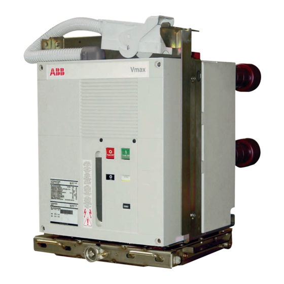
1VCP000169. For special installation requirements, please contact 5.3. Fixed circuit breaker ABB. The fixed circuit breaker (fig. 4) is the basic version The following versions are available: complete with structure and front protection screen. - Page 9 D I ST RI B U T I O N SO LU TI O N S Caption 1 Lever for manual closing spring charging 2 Signalling device for circuit breaker open/closed 3 Rating plate 4 Opening pushbutton 5 Closing pushbutton 6 Undervoltage release mechanical override (on request) 7 Signalling device for closing springs charged/discharged 8 Operation counter...
- Page 10 Tropicalization IEC: 60068-2-30, 60721-2-1 Electromagnetic compatibility IEC 62271-1 (*) This version cannot be sold loose; this version can only be supplied for 2000 A; Vmax/FH version must be ordered together with ABB UniGear 500R switchgear. (**) Up to 15 kV...
- Page 11 D IST RI BUT ION S OLUT IONS 11 11 Vmax 12 Vmax 17 Vmax/F 12 (*) Vmax/F 17 (*) Vmax 15 • • • • • • • • • • • • • • • 17.5 17.5 17.5 17.5...
- Page 12 VMAX - INSTALLATION AND SERVICE INSTRUCTIONS 12 12 — 5. Description 5.4. Withdrawable circuit breaker The withdrawable circuit breaker is fitted with special locks on the front crosspiece, which allow hooking up The withdrawable circuit breakers (see fig. 5) are into the corresponding couplings of the switchgear.
- Page 13 D I ST RI B U T I O N SO LU TI O N S Caption 1 Lever for manually charging the closing springs 2 Signalling device for circuit breaker open/closed 3 Rating plate 4 Opening pushbutton 5 Closing pushbutton 6 Signalling device for closing springs charged/discharged 7 Operation counter 8 Isolating contacts...
- Page 14 VMAX - INSTALLATION AND SERVICE INSTRUCTIONS — 5. Description 5.4.1. General characteristics of withdrawable circuit breakers (12 - 17.5 Circuit breaker kV) for UniGear ZS1 type units 550 mm wide, for PowerCube PB1 Use in switchgear/enclosure modules 600 mm wide and for UniSecswitchgear IEC 62271-100 CEI EN62271-100 (file 7642) Standards...
- Page 15 D IST RI BUT ION S OLUT IONS Vmax/L 12 Vmax/L 17 Vmax/W 12 Vmax/W 17 Vmax/W 15 Vmax/Sec 12 Vmax/Sec 17 UniGear 550 UniGear 550 PowerCube PowerCube PowerCube UniSec WBC/WBS UniSec WBC/WBS • • • • • • • •...
- Page 16 VMAX - INSTALLATION AND SERVICE INSTRUCTIONS — 5. Description 5.5. Characteristics of the electrical Auxiliary contacts of the circuit breaker 24 ... 250 V AC-DC accessories Rated current: = 10 A Insulation voltage: 2000 V 50 Hz (for 1 min) Shunt opening release (-MBO1);...
-
Page 17: Instructions For Operation Of The Circuit Breaker
D I ST RI B U T I O N SO LU TI O N S 17 17 — 6. Instructions for operating the circuit breaker 6.1. Safety indications Vmax circuit breakers guarantee a minimum IP2X degree of protection when installed in the following conditions: •... - Page 18 VMAX - INSTALLATION AND SERVICE INSTRUCTIONS — 6. Instructions for operating the circuit breaker 6.3. Circuit breaker closing and The geared motor automatically recharges the springs after each closing operation until the yellow opening operations signalling device (7) appears. Circuit breaker operation can be either manual or If the power is cut off during charging, the geared electrical (fig.
-
Page 19: Installation
• IEC60694/DIN VDE 0101 For special installation requirements or other • VDE 0105: Electrical installation service operating conditions, please contact ABB. • DIN VDE 0141: Earthing systems for installations with rated voltage above 1 kV The areas involved by the passage of •... - Page 20 VMAX - INSTALLATION AND SERVICE INSTRUCTIONS — Installation 7.2.3. Trip curves The following graphs show the number of closing-opening cycles (No.) allowed, of the vacuum interrupters, according to the breaking capacity (Ia). Fig. 8a Fig. 8b Caption Nr. Number of closing- opening cycles allowed for the vacuum interrupters.
- Page 21 D I ST RI B U T I O N SO LU TI O N S 21 21 7.3. Preliminary operations 7.6. Withdrawable circuit breakers with ABB truck for UniGear ZS1 • Clean the insulating parts with clean dry cloths. • Check that the top and bottom terminals are clean 550 mm wide, and UniSec...
- Page 22 VMAX - INSTALLATION AND SERVICE INSTRUCTIONS — Installation 7.7. Power circuit connections of Assembly procedure • Put the connections in contact with the circuit fixed circuit breakers breaker terminals taking care to avoid mechanical stresses (traction / compression) on, for example, 7.7.1.
- Page 23 D I ST RI B U T I O N SO LU TI O N S 7.8. Earthing For the fixed version circuit breaker, carry out earthing by means of the special screws marked with the relative symbol (see fig. 4). Clean and degrease the area around the screw to a diameter of about 30 mm and, on completion of assembly, cover the joint again with Vaseline grease.
- Page 24 VMAX - INSTALLATION AND SERVICE INSTRUCTIONS — Installation 7.10. Overall dimensions Vmax - Fixed circuit breakers 12-17.5 kV; 630-1250 A; 16-20-25-31.5 kA TN 1VCD003279-V3198 (*) Insulating shields for 17.5 kV...
- Page 25 D I ST RI B U T I O N SO LU TI O N S Vmax/F - Fixed circuit breakers for UniGear 500R 12-17.5 kV; 630-1250 A; 25-31.5 kA TN 1VCD003516-E0771 (*) Insulating shields for 17.5 kV...
- Page 26 VMAX - INSTALLATION AND SERVICE INSTRUCTIONS — Installation Vmax/F - Fixed circuit breakers for UniGear 500R 12-17.5 kV; 1600-2000 A; 25-31.5 kA TN 1VCD003558-V2315 18XM10 R 47 79,5 426,5 86,5 51,5 11,5 135,5 155,5 26,5 (*) Insulating shields for 17.5 kV...
- Page 27 D I ST RI B U T I O N SO LU TI O N S Vmax/L - Withdrawable circuit breakers for UniGear 550 12-17.5 kV; 630-1250 A; 16-20-25-31.5 kA TN 1VCD003334-V2296 (*) Insulating shields for 17.5 kV...
- Page 28 VMAX - INSTALLATION AND SERVICE INSTRUCTIONS — Installation Vmax/W - Withdrawable circuit breakers for PowerCube modules 12-17.5 kV; 630-1250 A; 16-20-25-31.5 kA TN 1VCD003280-V3519 Vmax/SEC - Withdrawable circuit breakers for UniSec switchgear 12-17.5 kV; 630-1250 A; 16-20-25 kA TN 1VCD003280-V3519 492 19,37 15,5 0,61 123,5 4,86...
-
Page 29: Putting Into Service
• check tightness of the power connections at the All the operations regarding putting circuit breaker terminals; into service must be carried out by ABB • establish the setting of the primary electronic personnel or by suitably qualified overcurrent release (if provided);... - Page 30 VMAX - INSTALLATION AND SERVICE INSTRUCTIONS — 8. Putting into service ITEM INSPECTED PROCEDURE POSITIVE CHECK Key lock (if provided). Open the circuit breaker, keep the opening Neither manual nor electrical closing takes pushbutton depressed, then turn the key and place remove it from the housing.
-
Page 31: Maintenance
(discoloured surface) (also see the “Repairs” regulations. Furthermore, is recommended that ABB paragraph). service personnel should be called in, at least to • If any anomalous conditions are found, appropriate check the service performances and for repair work. - Page 32 Dismantling and replacement of the operating mechanism (snap-on box) can • The nuts and screws are tightened in the factory only be carried out by ABB personnel or by qualified and specially trained per- sonnel, especially for the necessary adjustments.
- Page 33 Note discharged. Dismantling and replacement of the interrupter assembly can only be carried out by ABB personnel or by qualified and specially trained personnel, espe- All power supply sources must be disconnected and cially for the necessary adjustments. made safe against any reclosing during removal and installation work.
-
Page 34: Spare Parts And Accessories
• Shunt opening release following the instructions enclosed with • Additional shunt opening release the spare parts, by ABB personnel or by • Undervoltage release suitably qualified customer personnel • Time delay device for undervoltage release with in-depth knowledge of the •... - Page 35 D I ST RI B U T I O N SO LU TI O N S...
- Page 36 More product information: abb.com/mediumvoltage Your contact center: abb.com/contactcenters More service information: abb.com/service The data and illustrations are not binding. We reserve the right to modify the contents of this document following technical developments. © Copyright 2018 ABB. All rights reserved...