Advertisement
Quick Links
Owner's Manual
Pocket Multimeter
Model: 82351
CAUTION: Read, understand and
follow Safety Rules and Operating
Instructions in this manual before
using this product.
© Sears, Roebuck and Co., Hoffman Estates, IL 60179 U.S.A.
www.craftsman.com
ONE YEAR FULL WARRANTY
ONE YEAR FULL WARRANTY ON CRAFTSMAN MULTIMETER
If this CRAFTSMAN Multimeter fails to give complete satisfaction within one
year from the date of purchase, RETURN IT TO THE NEAREST SEARS
STORE OR OTHER CRAFTSMAN OUTLET IN THE UNITED STATES, and
Sears will replace it, free of charge.
This warranty gives you specific legal rights, and you may also have other
rights which vary from state to state.
Sears, Roebuck and Co., Dept. 817WA, Hoffman Estates, IL 60179
For Customer Assistance Call 9am - 5pm (ET)
Monday through Friday 1-888-326-1006
WARNING: USE EXTREME CAUTION IN THE USE OF THIS DEVICE.
Improper use of this device can result in injury or death. Follow all safeguards
suggested in this manual in addition to the normal safety precautions used in
working with electrical circuits. DO NOT service this device if you are not
qualified to do so.
SAFETY INSTRUCTIONS
This meter has been designed for safe use, but must be operated with
caution. The rules listed below must be carefully followed for safe operation.
1.
NEVER apply voltage or current to the meter that exceeds the specified
maximum:
Function
V DC or V AC
mA AC/DC
A AC/DC
Resistance, Diode Test,
Continuity
Temperature
2.
USE EXTREME CAUTION when working with high voltages.
3.
DO NOT measure voltage if the voltage on the "COM" input jack exceeds
600V above earth ground.
4.
NEVER connect the meter leads across a voltage source while the
function switch is in the current, resistance, or diode mode. Doing so can
damage the meter.
5.
ALWAYS discharge filter capacitors in power supplies and disconnect the
power when making resistance or diode tests.
6.
ALWAYS turn off power and disconnect test leads before opening the
covers to replace the fuse or battery.
7.
NEVER operate the meter unless the back cover and the battery and fuse
• Safety
covers are in place and fastened securely.
8.
If the equipment is used in a manner not specified by the manufacturer,
• Operation
the protection provided by the equipment may be impaired.
• Maintenance
• Español
SAFETY SYMBOLS
This symbol adjacent to another symbol, terminal or operating
device indicates that the operator must refer to an explanation
in the Operating Instructions to avoid personal injury or damage
to the meter.
061906
This WARNING symbol indicates a potentially hazardous
WARNING
situation, which if not avoided, could result in death or serious
injury.
This CAUTION symbol indicates a potentially hazardous
CAUTION
situation, which if not avoided, may result damage to the
product.
MAX
This symbol advises the user that the terminal(s) so marked
600V
must not be connected to a circuit point at which the voltage
with respect to earth ground exceeds 600V.
This symbol adjacent to one or more terminals identifies them
as being associated with ranges that may, in normal use, be
subjected to particularly hazardous voltages. For maximum
safety, the meter and its test leads should not be handled when
these terminals are energized.
This symbol indicates that a device is protected throughout by
double insulation or reinforced insulation.
Input Protection Limits
Maximum Input
600V AC and DC
500mA DC/AC
10A DC/AC (for 30 seconds max. every 15
minutes)
250V DC/AC
250V DC/AC
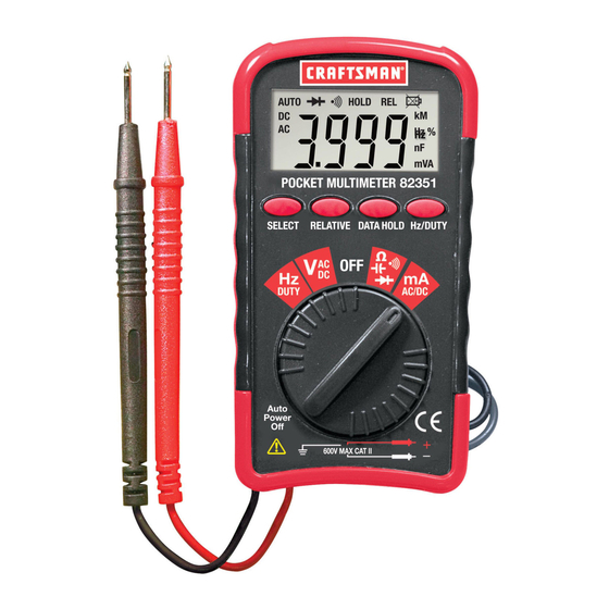
CONTROLS AND JACKS
1
1.
3 3/4 Digit (4000 count)
2
2.
RELATIVE button
3
3.
SELECT button
4
4.
DATA HOLD button
5.
Hz/DUTY button
5
6.
Function switch
6
7.
Rubber holster
7
SPECIFICATIONS
Function
Range
DC Voltage
400.0mV
4.000V, 40.00V,
400.0V,500V
AC Voltage
4.000V, 40.00V
(40-400Hz)
400.0V, 500V
DC Current
40.00mA
400.0mA
AC Current
40.00mA
(50-60 Hz)
400.0mA
Resistance
400.0 , 4.000k , 40.00k ,
400.0k
4.000M
40.00M
Capacitance
4.000nF
40.00nF
400.0nF
4.000 F, 40.00 F, 200.0 F ±(10.0% reading + 15 digits)
Frequency
9.999Hz, 99.99Hz, 999.9Hz,
9.999kHz, 99.99kHz,
999.9kHz, 10MHz
Duty Cycle
0.1-99%
Max input voltage
500V AC/DC
Input Sensitivity,
10Vrms min. <9.999KHz
(Frequency Ranges)
40Vrms min. >99.99KHz
Diode Test
Test current 1mA max., open circuit voltage of 1.5V
typical
Continuity Check
Audible signal if the resistance is < 60
Display
4000 count 3
digit LCD
Over range indication
LCD displays "OL"
Polarity
Minus (-) sign for negative polarity.
Low Battery Indication "BAT" symbol indicates low battery condition.
Battery
CR2032 3V Lithium
o
o
o
Operating Temperature 41
F to 104
F (5
C to 40
o
o
o
Storage Temperature
14
F to 122
F (-10
C to 50
Operating Humidity
Max 80% up to 87ºF (31ºC) decreasing linearly to
50% at 104ºF (40ºC)
Storage Humidity
<80%
Operating Altitude
7000ft. (2000meters) maximum.
Weight
1.7oz (50g)
Size
4.25x2.2x.5" (108x56x11.5mm)
Safety
For indoor use and in accordance with the
requirements for double insulation to IEC1010-1
(1995): EN61010-1 (1995) Overvoltage Category II
600V, Pollution Degree 2. UL, CE Approved
Accuracy
±(0.7% reading + 3 digits)
±(1.0% reading + 3 digits)
±(1.3% reading + 3 digits)
±(1.0% reading + 10 digits)
±(2.3% reading + 5 digits)
±(2.0% reading + 5 digits)
±(2.5% reading + 10 digits)
±(2.0% reading + 5 digits)
±(5.0% reading + 5 digits)
±(10.0% reading + 5 digits)
±(5.0% reading + 0.3nF)
±(5.0% reading + 30 digits)
±(3.0% reading + 15 digits)
±(2.0% reading + 5 digits)
±(2.0% reading + 5 digits)
o
C)
o
C)
Advertisement

Related Manuals for Craftsman 82351


Summary of Contents for Craftsman 82351
- Page 1 Polarity Minus (-) sign for negative polarity. If this CRAFTSMAN Multimeter fails to give complete satisfaction within one product. Low Battery Indication “BAT” symbol indicates low battery condition. year from the date of purchase, RETURN IT TO THE NEAREST SEARS...
- Page 2 CAPACITANCE MEASUREMENT BATTERY INSTALLATION DATA HOLD BUTTON The Data Hold function allows the meter to “freeze” a measurement for later WARNING: To avoid electric shock, disconnect power to the unit under WARNING: To avoid electric shock, disconnect the test leads from any reference test and discharge all capacitors before taking any capacitance source of voltage before removing the battery cover.