ABB REF 541 Product Manual
Feeder terminal
Hide thumbs
Also See for REF 541:
- User manual (36 pages) ,
- Technical reference manual, general (132 pages) ,
- Technical reference manual (118 pages)
Table of Contents
Advertisement
Quick Links
Advertisement
Table of Contents

Related Manuals for ABB REF 541


Summary of Contents for ABB REF 541
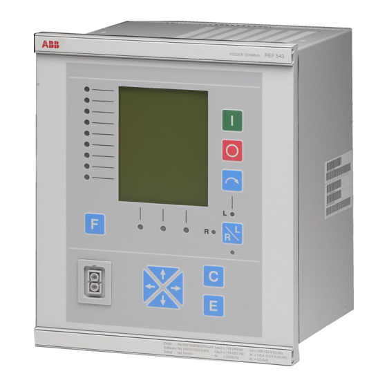
- Page 1 Feeder Terminal REF 541, REF 543, Product Guide 545.
- Page 3 Feeder Terminal REF 541, REF 543, REF 545. 1MRS750443-MBG Issued: June 1999 Status: Updated Version: G/28.05.2010 Data subject to change without notice Features • Feeder terminal for protection, control, • Additional functions including synchro- measurement and supervision of medium check, frequency protection, capacitor voltage networks.
- Page 4 Feeder Terminal REF 541, REF 543, REF 545. 1MRS750443-MBG Application The REF 541, REF 543 and REF 545 feeder Application area also covers protection func- terminals are designed to be used for protec- tions for a large variety of applications, e.g.
- Page 5 The status of different objects, e.g. open/ includes pulse counter inputs. The number of close/undefined, displayed in the MIMIC pulse inputs varies from 7 (REF 541) to 10 view can be freely designed. (REF 545) according to the REF variant.
- Page 6 Feeder Terminal REF 541, REF 543, REF 545. 1MRS750443-MBG Other functions Each analog channel is separately configured with the Relay Configuration Tool. Both the measuring unit for each analog channel and Low auxiliary voltage indication the type of signal to be measured are to be The REF 54_ feeder terminal is provided configured.
- Page 7 The alarm channels include time tagging for detected alarms. The time tagging principle RTD/analogue inputs used depends on the operation mode. The REF 541 and REF 543 feeder terminals equipped with an RTD/analogue module Interlocking LED indicator (RTD1) have eight general purpose analogue The interlocking LED indicates that control inputs for DC measurement.
- Page 8 Feeder Terminal REF 541, REF 543, REF 545. 1MRS750443-MBG • optically isolated serial communication IEC 61850 communication using SPA-ZC port 400 on the rear connector X3.2 The 9-pin D-type subminiature male connec- • backlight and contrast control tor (RS-232 connection) on the rear panel •...
- Page 9 Feeder Terminal REF 541, REF 543, REF 545. 1MRS750443-MBG Feeder terminal configuration Lon network configuration The LON Network Tool is used for binding The Relay Configuration Tool, based on the network variables between RED 500 termi- IEC 61131-3 standard, is used for configuring nals.
- Page 10 Feeder Terminal REF 541, REF 543, REF 545. 1MRS750443-MBG Profibus is available through the SPA-ZC 302 The digital input and output contacts of the Gateway and IEC 61850 is available through feeder terminal are connected to the multi- the SPA-ZC 400 Ethernet Adapter pole connectors.
- Page 11 Feeder Terminal REF 541, REF 543, REF 545. 1MRS750443-MBG X4.1 Mains PS1_4_ACFail PS1_4_TempAlarm X1.1 X3.2 Ch 10, VT4 100V SERIAL BUS Ch 9, VT3 100V X3.3 SERIAL BUS Ch 8, VT2 100V X4.1 I R F Ch 7, VT1 100V...
- Page 12 Feeder Terminal REF 541, REF 543, REF 545. 1MRS750443-MBG X4.1 PS2_4_ACFail Mains PS2_4_TempAlarm X1.1 X3.2 100V Ch 10, VT4 SERIAL BUS 100V Ch 9, VT3 X3.3 SERIAL BUS 100V Ch 8, VT2 X4.1 I R F 100V Ch 7, VT1...
- Page 13 Feeder Terminal REF 541, REF 543, REF 545. 1MRS750443-MBG A050205 Fig. 6 Terminal diagram of the RTD/analog module Auxiliary voltage The feeder terminal is provided with a 48- hour capacitor back-up protection that For its operation, the REF 54_ terminal,...
- Page 14 Feeder Terminal REF 541, REF 543, REF 545. 1MRS750443-MBG Technical data Table 1: General functions Function Description INDRESET Resetting of operation indicators, latched output signals, registers and waveforms i.e. the disturbance recorder MMIWAKE Activation of HMI backlight SWGRP1 Switchgroup SWGRP1...
- Page 15 Feeder Terminal REF 541, REF 543, REF 545. 1MRS750443-MBG Table 2: Standard functions Function Description Comparison to greater or less Complement Extensible OR connection R_TRIG Rising edge detector REAL_TO_* Type conversion from REAL to USINT / UINT / UDINT / SINT / INT /...
- Page 16 Feeder Terminal REF 541, REF 543, REF 545. 1MRS750443-MBG Table 4: Control functions Function ANSI IEC symbol Description device no. CO3DC1 CO3DC1 I<->O 3DC1 Three-state disconnector (1) with indication CO3DC2 CO3DC2 I<->O 3DC2 Three-state disconnector (2) with indication COCB1 COCB1 I<->O CB1...
- Page 17 Feeder Terminal REF 541, REF 543, REF 545. 1MRS750443-MBG Power factor controller settings Power factor controller, COPFC The number of capacitor banks to be controlled 1...4 The relational step sizes and the type of the switching 1:1:1:1 linear; 1:1:1:1 circul.; 1:1:2:2 circul.;...
- Page 18 Feeder Terminal REF 541, REF 543, REF 545. 1MRS750443-MBG Table 5: Measurement functions Function ANSI Description device no. symbol MEFR1 System frequency measurement MEPE7 Three-phase power and energy measurement MEVO1A Residual voltage measurement, stage A MEVO1B Uo_B Uo_B Residual voltage measurement, stage B...
- Page 19 Feeder Terminal REF 541, REF 543, REF 545. 1MRS750443-MBG Analogue output on RTD/analogue module, MEAO1...4 (AO1...AO4) The analogue output function blocks handle the scaling of any internal REAL type IEC 61131-3 based signal to fit a selectable 0…20 mA or 4…20 mA range for use with the outputs on the RTD/analogue module.
- Page 20 Feeder Terminal REF 541, REF 543, REF 545. 1MRS750443-MBG Table 6: Protection functions Function ANSI Description device no. symbol AR5Func O-->I Auto-reclose function (5 shots) CUB1Cap 51NC-1 dI>C Current unbalance protection for shunt capacitor banks CUB3Cap 51NC-2 3dI>C Three-phase current unbalance protection for H-bridge connected...
- Page 21 Feeder Terminal REF 541, REF 543, REF 545. 1MRS750443-MBG Settings of protection functions Three-phase non-directional overcurrent protection, low-set stage, NOC3Low, 3I> (51-1) Start current 0.10…5.00 x In Operate time at DT mode 0.05…300.00 s Time multiplier at IDMT mode 0.05…1.00...
- Page 22 Feeder Terminal REF 541, REF 543, REF 545. 1MRS750443-MBG Three-phase directional O/C function, low-set stage, DOC6Low, 3I>(67-1) Operation mode Not in use; Definite time Extremely inv.; Very inverse Normal inverse Long-time inv.; RI-type inverse RD-type inverse Start current 0.05…40.00 x In Operate time 0.05…300.00 s...
- Page 23 Feeder Terminal REF 541, REF 543, REF 545. 1MRS750443-MBG Note! The values below apply when f/fn = 0.95...1.05 Operation accuracy 0.1...10 x In: ±2.5% of set value or ±0.01 x In 10...40 x In: ±5.0% of set value ±2.5% of measured voltage or ±0.01 x Un ±2...
- Page 24 Feeder Terminal REF 541, REF 543, REF 545. 1MRS750443-MBG Note! The values below apply when f/fn = 0.95...1.05 Operation accuracy ±2.5% of set value or + 0.01 x In Start time Injected currents > 2.0 x start current: internal time < 32 ms total time <...
- Page 25 Feeder Terminal REF 541, REF 543, REF 545. 1MRS750443-MBG Directional earth-fault protection, high-set stage, DEF2High, Io>> (67N-2), and instantaneous stage, DEF2Inst, Io>>> (67N-3) Start current 1.0…500.0% of In Start voltage 2.0…100.0% of Un Operate time 0.1…300.0 s Operation mode Not in use...
- Page 26 Feeder Terminal REF 541, REF 543, REF 545. 1MRS750443-MBG Residual overvoltage protection, high-set stage, ROV1High, Uo>> (59N-2), and instantaneous stage, ROV1Inst, Uo>>> (59N-3) Start voltage 2.0…100.0% of Un Operate time 0.05…300.00 s Operation mode Not in use Definite time Measuring mode...
- Page 27 Feeder Terminal REF 541, REF 543, REF 545. 1MRS750443-MBG Three-phase thermal overload protection for motors, generators and transformers, TOL3Dev, 3Ithdev> (49M/G/T) BASIC SETTINGS Starting current of the motor 0.10...10.00 x In Max. starting time permitted for the motor 0.1...120.0 s Number of starts allowed from cold state 1...3...
- Page 28 Feeder Terminal REF 541, REF 543, REF 545. 1MRS750443-MBG Three-phase overvoltage protection, low-set stage, OV3Low, 3U> (59-1) Start voltage 0.10…1.60 x Un Operate time 0.05…300.00 s Time multiplier 0.05…1.00 Operation mode Not in use Definite time A curve B curve Measuring mode Phase-to-phase voltages;...
- Page 29 Feeder Terminal REF 541, REF 543, REF 545. 1MRS750443-MBG Note! The values below apply when f/fn = 0.95...1.05 Operation accuracy ±35 ms Start time Injected voltages < 0.5 x start voltage: internal time < 32 ms total time < 40 ms Reset time 40...1000 ms (depends on the minimum pulse width set for...
- Page 30 Feeder Terminal REF 541, REF 543, REF 545. 1MRS750443-MBG Note! The values below apply when f/fn = 0.95...1.05 Operation accuracy ± 2.5% of set value or ± 0.01 x Un Trip time U2> operation: Injected negative-seq. voltage = 1.1 x start value: internal time <...
- Page 31 Feeder Terminal REF 541, REF 543, REF 545. 1MRS750443-MBG Start-up supervision for motors, MotStart, I t n< (48) Start current (for motor) 1.0...10.0 x In Start time (for motor) 0.3...250.0 s Time-based restart inhibit limit 1.0...500.0 s Countdown rate of the time counter 2.0...250.0 s/h...
- Page 32 Feeder Terminal REF 541, REF 543, REF 545. 1MRS750443-MBG Current unbalance protection for shunt capacitor banks, CUB1Cap, dI>C (51NC-1) Operation mode Not in use; Definite time; Extremely inv.; Very inv.; Normal inv.; Long-time inv.; RI-type inv.; RD-type inv. Alarm mode Normal mode;...
- Page 33 Feeder Terminal REF 541, REF 543, REF 545. 1MRS750443-MBG Three-phase current unbalance protection for H-bridge connected shunt capacitor banks, CUB3Cap, 3dI>C (51NC-2) Operation mode Not in use; Definite time; Extremely inv.; Very inv.; Normal inv.; Long-time inv.; RI-type inv.; RD-type inv.
- Page 34 Feeder Terminal REF 541, REF 543, REF 545. 1MRS750443-MBG Phase discontinuity protection, CUB3Low, Iub> (46) Start unbalance 10.0…95.0% Operate time 1.0…300.0 s Operation mode Not in use Definite time Note! The values below apply when f/fn = 0.95...1.05 Operation accuracy ±2.5% of set value or ±1% unit...
- Page 35 Feeder Terminal REF 541, REF 543, REF 545. 1MRS750443-MBG Settings of power quality functions Current waveform distortion measurement, PQCU3H, PQ 3inf (PQ 3inf) The current waveform distortion measurement PQCU3H is used for measurement and statistical analysis of current waveform distortion. The standards concerning voltage distortion measurement are applied to current distortion measurement in PQCU3H.
- Page 36 Feeder Terminal REF 541, REF 543, REF 545. 1MRS750443-MBG Monitored values THD (3 sec and 10 min mean values) 0.0 ... 120.0% Harmonic components from 1st to 13th (3 sec mean values) 0.0 ... 120.0% Un Harmonic components from 2nd to 13th (10 min mean values) 0.0 ...
- Page 37 Feeder Terminal REF 541, REF 543, REF 545. 1MRS750443-MBG Table 8: Energizing inputs Voltage inputs rated voltage 100 V/110 V/115 V/120 V (parameterization) voltage withstand, continuously 2 x U (240 V) burden at rated voltage <0.5 VA Sensor inputs, max 9 AC voltage range 9.4 V RMS...
- Page 38 Feeder Terminal REF 541, REF 543, REF 545. 1MRS750443-MBG Table 10: Digital inputs Power supply version PS1/240 V (High) PS1/240 V (Medium), PS1/48 V (Low), PS2/240 V PS2/48V Input voltage, dc 220 V 110/125/220 V 24/48/60/110/125/ 220 V Operating range, dc 155…265 V...
- Page 39 Feeder Terminal REF 541, REF 543, REF 545. 1MRS750443-MBG Table 13: Power outputs Max system voltage 250 V ac/dc Continuous carry Make and carry for 0.5 s 30 A Make and carry for 3 s 15 A Breaking capacity when control circuit time constant 5 A/3 A/1 A L/R <40 ms, at 48/110/220 V dc...
- Page 40 Feeder Terminal REF 541, REF 543, REF 545. 1MRS750443-MBG Table 17: Electromagnetic compatibility tests The EMC immunity test level fulfills the requirements listed below 1 MHz burst disturbance test, common mode 2.5 kV class III, IEC 60255-22-1 differential mode 1.0 kV...
- Page 41 Feeder Terminal REF 541, REF 543, REF 545. 1MRS750443-MBG Table 18: Data communication Rear interface, connector X3.1 not used, reserved for future purposes Rear interface, connector X3.2 RS-232 connection RER 123 fibre-optic Bus Connection Module protocols SPA, IEC_103, DNP 3.0...
- Page 42 Feeder Terminal REF 541, REF 543, REF 545. 1MRS750443-MBG Table 19: General Toolboxes CAP 501 CAP 505 LNT 505 Event recording all events are recorded in higher level syntax: reason, time, date the last 100 events are recorded Data recording...
- Page 43 Hardware number: 115, 118, 127, 129, 133 Functionality level: C = Control, B = Basic, M = Multi Software revision: A, B, C, D, E, F, G, H, K Feeder terminal type: REF 541, REF 543, REF 545 A050601 The functionality level (C) determines the...
- Page 44 Feeder Terminal REF 541, REF 543, REF 545. 1MRS750443-MBG The REF 541, REF 543 and REF 545 feeder Terminals can optionally be ordered with an terminals differ from each other as to the ANSI front panel. number of digital inputs and outputs as fol- lows.
- Page 45 Feeder Terminal REF 541, REF 543, REF 545. 1MRS750443-MBG Functionality levels, protection functions FUNCTIONALITY LEVELS ANSI Function Code REF541/3/5 REF541/3/5 REF541/3/5 Code Symbol CONTROL BASIC MULTI 59N-3 Uo >>> Residual overvoltage, ROV1Inst instantaneous stage OVERLOAD 3Ith> Three-phase thermal TOL3Cab overload (feeders & cables)
- Page 46 Feeder Terminal REF 541, REF 543, REF 545. 1MRS750443-MBG Functionality levels, protection functions FUNCTIONALITY LEVELS ANSI Function Code REF541/3/5 REF541/3/5 REF541/3/5 Code Symbol CONTROL BASIC MULTI LOAD SHEDDING AND RESTORATION 81-1 Underfrequency or Freq1St1 overfrequency inc. rate of change, stage 1...
- Page 47 Feeder Terminal REF 541, REF 543, REF 545. 1MRS750443-MBG Functionality levels, other functions FUNCTIONALITY LEVELS ANSI Function Code REF541/3/ REF541/3/ REF541/3/ Code Symbol 5 BASIC 5 MULTI CONTROL 3U_B 3U_B Three-phase voltage, B MEVO3B stage Residual voltage MEVO1A Uo_B Uo_B...
- Page 48 Feeder Terminal REF 541, REF 543, REF 545. 1MRS750443-MBG Functionality levels, other functions FUNCTIONALITY LEVELS ANSI Function Code REF541/3/ REF541/3/ REF541/3/ Code Symbol 5 BASIC 5 MULTI CONTROL CO3DC1 I<->O Three state disconnector 1, CO3DC1...2 CO3DC2 3DC1, 3DC2 (3 state inputs / 4 control outputs) COIND1…...
- Page 49 Feeder Terminal REF 541, REF 543, REF 545. 1MRS750443-MBG Optional functionality Function Code Ordering number ANSI Function Order Code device no. Symbol CAPACITOR BANK PROTECTION Three-phase overload protection 3I>3I< OL3Cap 1MRS100116 for shunt capacitor banks Current unbalance protection for 51NC-1 dI>C...
- Page 50 Feeder Terminal REF 541, REF 543, REF 545. 1MRS750443-MBG Overview of REF hardware configurations Hardware modules of REF 541 Order number Analogue interface Sensor channels (current or voltage) 9 9 9 9 9 9 Current transformer 1/5 A 4 4 4 4 4 4 4 4 4 4 4 4 4 4 4 4 4 4 4 4 Current transformer 0.2/1 A...
- Page 51 Feeder Terminal REF 541, REF 543, REF 545. 1MRS750443-MBG Hardware modules of REF 543 Order number Analogue interface Sensor channels (current or voltage) 9 9 9 9 9 9 Current transformer 1/5 A 4 4 4 4 4 4 4 4 4 4 4 4 4 4 4 4 4 4 4 4 Current transformer 0.2/1 A...
- Page 52 Feeder Terminal REF 541, REF 543, REF 545. 1MRS750443-MBG Hardware modules of REF 545 Order number Analogue interface Sensor channels (current or voltage) 9 9 9 Current transformer 1/5 A 4 4 4 4 4 4 4 4 4 4 Current transformer 0.2/1 A...
- Page 53 Feeder Terminal REF 541, REF 543, REF 545. 1MRS750443-MBG Parts and assembly forms a whole for which no separate spare parts can be supplied. In the event of mal- descriptions function, please consult your feeder terminal To achieve the best possible operation accu- supplier.
- Page 54 Feeder Terminal REF 541, REF 543, REF 545. 1MRS750443-MBG Application examples 3I > 50/51 > 50N/51N CBFP * /62 CBCM REF 54_ SPAU 341 p> I > CBFP * /62 SPAD 346C 50/51 3I > 3I > & REA 101 CBCM 3U >...
- Page 55 Feeder Terminal REF 541, REF 543, REF 545. 1MRS750443-MBG 3I > 50/51 > 50N/51N CBCM CBFP * /62 REF 54_ SPAU 341 I > p> CBFP * /62 SPAD 346C 50/51 3I > 3I > & REA 101 > CBCM 3U >...
- Page 56 Feeder Terminal REF 541, REF 543, REF 545. 1MRS750443-MBG 3I > 50/51 > CBCM > > DI> f < CBFP * /62 REF 54_ EXFDR1 Fig. 9 An REF 54_ feeder terminal used for the protection, control, measurement and supervision func- tions of a utility feeder (main single-line diagram presentation).
- Page 57 Feeder Terminal REF 541, REF 543, REF 545. 1MRS750443-MBG 3U > 3U > 3U < 3U < > > f < f < REF 54_ REF 54_ EXMEAS1 Fig. 10 REF 54_ feeder terminals used for the protection, control, measurement and supervision functions of a utility/industrial measurement cubicle (main single-line diagram presentation).
- Page 58 Feeder Terminal REF 541, REF 543, REF 545. 1MRS750443-MBG 3I > 50/51 > 50N/51N > CBCM CBFP * /62 REF 54_ SPAU 341 I > CBFP * /62 p> SPAD 346C 50/51 3I > 3I > & REA 101 CBCM 3I>...
- Page 59 Feeder Terminal REF 541, REF 543, REF 545. 1MRS750443-MBG 3I> > CBCM SYNC f < 3U > 3U < CBFP * /62 REF 54_ EXFDR3 3I > & REA 101 Fig. 12 An REF 54_ feeder terminal and an REA arc monitoring system (main single-line diagram presen- tation) used for the protection, control, measurement and supervision functions of a utility/industrial ring/meshed network cable feeder.
- Page 60 Feeder Terminal REF 541, REF 543, REF 545. 1MRS750443-MBG 3I > 50/51 > 50N/51N > CBCM DI> CBFP * /62 REF 54_ EXFDR4 Fig. 13 An REF 54_ feeder terminal used for the protection, control, measurement and supervision func- tions of a utility/light industrial cable feeder (main single line diagram presentation). The earthing of...
- Page 61 Feeder Terminal REF 541, REF 543, REF 545. 1MRS750443-MBG 3I > 50/51 > 50N/51N > CBCM CBFP * /62 REF 54_ SPAU 341 p> I > > > CBFP * /62 SPAD 346C 3I > 3I> & > 50N/51N REA 101 CBCM 3U >...
- Page 62 Feeder Terminal REF 541, REF 543, REF 545. 1MRS750443-MBG 3I > 50/51 > 50N/51N CBCM > DI> f < CBFP * /62 REF 54_ EXFDR2 Fig. 15 An REF 54_ feeder terminal used for the protection, control, measurement and supervision func- tions of a utility feeder (main single-line diagram presentation).
- Page 63 Feeder Terminal REF 541, REF 543, REF 545. 1MRS750443-MBG 3U> 3U< REF 54_ 3I> 50/51 I > 3I>3I< 51C,37C, CBCM 51NC DI> CBFP 62BF REF 54_ Fig. 16 REF 54_ used for the protection of a double Y connected capacitor bank...
- Page 64 Feeder Terminal REF 541, REF 543, REF 545. 1MRS750443-MBG 3U> 3U< < > > REF 54_ 3I> 50/51 I > I > CBCM I t, n< 48,14,66 CBFP 62BF REF 54_ Fig. 17 REF 54_ used for the protection of a motor with direct-on-line starting...
- Page 65 Feeder Terminal REF 541, REF 543, REF 545. 1MRS750443-MBG = multiple-stage three-phase overcurrent protection, low-set, high-set and instantaneous 3I > 50/51 stage available 3I> = multiple-stage three-phase directional overcurrent protection, low-set, high-set and instantaneous stage available > = multiple-stage directional earth-fault protection, low-set, high-set and instantaneous stage available >...
- Page 66 Feeder Terminal REF 541, REF 543, REF 545. 1MRS750443-MBG , n< = three-phase start-up supervision for motors 48, 14, 16 = three-phase thermal overload protection for devices ,> ,<U > 27, 47, 59 = phase-sequence voltage protection, stages 1 and 2 available DI>...
- Page 67 Feeder Terminal REF 541, REF 543, REF 545. 1MRS750443-MBG = energy counter, forward or reverse active / reactive energy = current waveform distortion measurement 3I~harm 3U~harm = voltage waveform distortion measurement = annunciating, event generating and value recording functions = disturbance recorder...
- Page 68 Feeder Terminal REF 541, REF 543, REF 545. 1MRS750443-MBG Application selection tables for REF 541, REF 543 and REF 545 functions Table 20: Protection functions Function ANSI IEC symbol Description device no. AR5Func O-->I Auto-reclose function (5 shots) CUB1Cap 51NC-1 dI>C...
- Page 69 Feeder Terminal REF 541, REF 543, REF 545. 1MRS750443-MBG Table 21: Measurement functions Function ANSI device IEC symbol Description MEAI1 General measurement 1 / analog input on RTD/analog module MEAI2 General measurement 2 / analog input on RTD/analog module MEAI3...
- Page 70 Feeder Terminal REF 541, REF 543, REF 545. 1MRS750443-MBG Table 23: Control functions Function ANSI device IEC symbol Description COIND2 COIND2 I<->O IND2 Switching device 2 indication COIND3 COIND3 I<->O IND3 Switching device 3 indication COIND4 COIND4 I<->O IND4 Switching device 4 indication...
- Page 71 Feeder Terminal REF 541, REF 543, REF 545. 1MRS750443-MBG References Additional information Feeder Terminal REF 54_ Technical 1MRS750527-MUM ReferenceManual, General Technical Descriptions of Functions 1MRS750889-MCD (CD-ROM only) Installation Manual 1MR 750526-MUM Operator’s Manual 1MR 750500-MUM Technical Reference Manual RER 103...
- Page 76 ABB Oy Distribution Automation P.O. Box 699 FI-65101 Vaasa, FINLAND Tel +358 10 22 11 Fax +358 10 224 1094 www.abb.com/substationautomation...