Table of Contents
Advertisement
Quick Links
Download this manual
See also:
Instruction Manual
QQ
3 7 63 1515 0
SERVICE MANUAL
1
2004
MA049
TE
L 13942296513
1
PRECAUTION. . . . . . . . . . . . . . . . . . . . . . . . . . . . . . . . . . . . . . . . . . . . . . . . . . . . . . . . . . . . . . . . . . . . . . . . . 1-3
2
SPECIFIC SERVICE INSTRUCTIONS . . . . . . . . . . . . . . . . . . . . . . . . . . . . . . . . . . . . . . . . . . . . . . . . . . . . . . 1-5
3
DISASSEMBLY . . . . . . . . . . . . . . . . . . . . . . . . . . . . . . . . . . . . . . . . . . . . . . . . . . . . . . . . . . . . . . . . . . . . . . . 1-6
4
ADJUSTMENT . . . . . . . . . . . . . . . . . . . . . . . . . . . . . . . . . . . . . . . . . . . . . . . . . . . . . . . . . . . . . . . . . . . . . . . 1-27
5
TROUBLE SHOOTING . . . . . . . . . . . . . . . . . . . . . . . . . . . . . . . . . . . . . . . . . . . . . . . . . . . . . . . . . . . . . . . . . 1-28
.
http://www.xiaoyu163.com
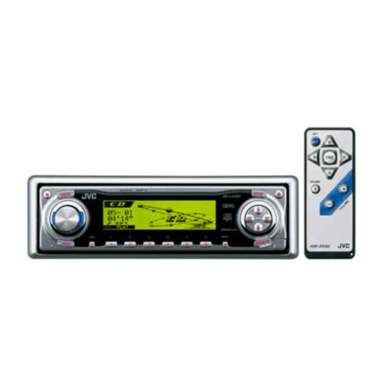
CD RECEIVER
KD-LH305
TABLE OF CONTENTS
x
u163
y
i
COPYRIGHT © 2004 VICTOR COMPANY OF JAPAN, LIMITED
http://www.xiaoyu163.com
2 9
8
Q Q
3
6 7
1 3
1 5
co
.
9 4
2 8
Area suffix
U --------------------- Other Areas
0 5
8
2 9
9 4
2 8
m
No.MA049
9 9
9 9
2004/1
Advertisement
Chapters
Table of Contents

Related Manuals for JVC KD-LH305


Summary of Contents for JVC KD-LH305
-
Page 1: Table Of Contents
3 7 63 1515 0 SERVICE MANUAL CD RECEIVER MA049 2004 KD-LH305 Area suffix U --------------------- Other Areas L 13942296513 TABLE OF CONTENTS PRECAUTION............... . . 1-3 SPECIFIC SERVICE INSTRUCTIONS . - Page 2 http://www.xiaoyu163.com 3 7 63 1515 0 SPECIFICATION AUDIO AMPLIFIER SECTION Maximum Power Output Front 50 W per channel Rear 50 W per channel 19 W per channel into 4 Ω, 40 Hz to 20 000 Hz at no more than Continuous Power Output Front (RMS)
-
Page 3: Precaution
http://www.xiaoyu163.com 3 7 63 1515 0 SECTION 1 PRECAUTION Safety Precautions Burrs formed during molding may be left over on some parts of the chassis. Therefore, pay attention to such burrs in the case of preforming repair of this system. Please use enough caution not to see the beam directly or touch it in case of an adjustment or operation check. - Page 4 http://www.xiaoyu163.com 3 7 63 1515 0 Preventing static electricity Electrostatic discharge (ESD), which occurs when static electricity stored in the body, fabric, etc. is discharged, can destroy the laser diode in the traverse unit (optical pickup). Take care to prevent this when performing repairs. 1.2.1 Grounding to prevent damage by static electricity Static electricity in the work area can destroy the optical pickup (laser diode) in devices such as CD players.
-
Page 5: Specific Service Instructions
http://www.xiaoyu163.com 3 7 63 1515 0 SECTION 2 SPECIFIC SERVICE INSTRUCTIONS This service manual does not describe SPECIFIC SERVICE INSTRUCTIONS. L 13942296513 u163 (No.MA049)1-5 http://www.xiaoyu163.com... -
Page 6: Disassembly
http://www.xiaoyu163.com 3 7 63 1515 0 SECTION 3 DISASSEMBLY Main body 3.1.1 Removing the front panel assembly Front panel assembly (See Fig.1) (1) Push the detach button in the lower right part of the front panel assembly. (2) Remove the front panel assembly. Detach button Fig.1 3.1.2 Removing the heat sink... - Page 7 http://www.xiaoyu163.com 3 7 63 1515 0 3.1.3 Removing the top chassis assembly Bottom chassis assembly (See Figs.3 to 6) • Prior to performing the following procedures, remove the heat sink. Reference: Remove the front panel assembly as required. (1) From the bottom side of the main body, remove the two screws C attaching the top chassis assembly to the bottom chassis assembly.
- Page 8 http://www.xiaoyu163.com 3 7 63 1515 0 3.1.4 Removing the front chassis Top chassis assembly (See Figs.7 and 8) • Prior to performing the following procedure, remove the front panel assembly, heat sink and top chassis assembly. (1) From the both sides of the top chassis assembly, remove the two screws E attaching the front chassis.
- Page 9 http://www.xiaoyu163.com 3 7 63 1515 0 3.1.6 Removing the CD mechanism assembly Top chassis (See Fig.10) • Prior to performing the following procedures, remove the front panel assembly, heat sink and top chassis assembly. Reference: Remove the mechanism control board as required. (1) From the inside of the top chassis assembly, remove the three screws G attaching the CD mechanism assembly.
- Page 10 http://www.xiaoyu163.com 3 7 63 1515 0 3.1.8 Removing the rear bracket Wire Main board (See Fig.13) • Prior to performing the following procedures, remove the front Wire holde panel assembly, heat sink, top chassis assembly and main Rear bracket board. (1) From the rear side of the main board, remove the wire from the rear bracket in the direction of the arrow.
- Page 11 http://www.xiaoyu163.com 3 7 63 1515 0 3.1.10 removing the front board (See Figs.15 to 18) Rear cover assembly • Prior to performing the following procedures, remove the front panel assembly. (1) From the rear side of the front panel assembly, remove the four screws P attaching the rear cover assembly to the front panel assembly.
- Page 12 http://www.xiaoyu163.com 3 7 63 1515 0 CD Mechanism section 3.2.1 Removing the top cover (See Figs.1 and 2) (1) Remove the four screws A on the both side of the body. (2) Lift the front side of the top cover and move the top cover backward to release the two joints a.
- Page 13 http://www.xiaoyu163.com 3 7 63 1515 0 3.2.2 Removing the connector board Wires (See Figs.3 to 5) CAUTION: Before disconnecting the flexible wire from the pickup, solder the short-circuit point on the pickup. No observance of this in- struction may cause damage of the pickup. (1) Remove the screw B fixing the connector board.
- Page 14 http://www.xiaoyu163.com 3 7 63 1515 0 3.2.3 Removing the DET switch (See Figs.6 and 7) (1) Extend the two tabs c of the feed sw. holder and pull out the switch. (2) Unsolder the DET switch wire if necessary. switch Connector board Pickup...
- Page 15 http://www.xiaoyu163.com 3 7 63 1515 0 3.2.4 Removing the chassis unit (See Figs.8 and 9) • Prior to performing the following procedure, remove the top Chassis unit cover and connector board. Suspension spring (L) Suspension spring (R) (1) Remove the two suspension springs (L) and (R) attaching the chassis unit to the frame.
- Page 16 http://www.xiaoyu163.com 3 7 63 1515 0 3.2.5 Removing the clamper assembly (See Figs.10 and 11) • Prior to performing the following procedure, remove the top cover. (1) Remove the clamper arm spring. Clamper arm spring (2) Move the clamper assembly in the direction of the arrow to release the two joints d.
- Page 17 http://www.xiaoyu163.com 3 7 63 1515 0 3.2.6 Removing the loading / feed motor assembly (See Figs.12 and 13) • Prior to performing the following procedure, remove the top cover, connector board and chassis unit. (1) Remove the screw C and move the loading / feed motor as- sembly in the direction of the arrow to remove it from the chassis rivet assembly.
- Page 18 http://www.xiaoyu163.com 3 7 63 1515 0 3.2.7 Removing the pickup unit Pickup unit (See Figs.14 to 18) • Prior to performing the following procedure, remove the top cover, connector board and chassis unit. (1) Remove the screw D and pull out the pu. shaft holder from Part e the pu.
- Page 19 http://www.xiaoyu163.com 3 7 63 1515 0 3.2.9 Removing the trigger arm Joint k (See Figs.19 and 20) • Prior to performing the following procedure, remove the top cover, connector board and clamper unit. (1) Turn the trigger arm in the direction of the arrow to release Trigger arm the joint k and pull out upward.
- Page 20 http://www.xiaoyu163.com 3 7 63 1515 0 3.2.11 Removing the mode sw. / select lock arm Link plate Joint t (See Figs.22 and 23) Mode sw. • Prior to performing the following procedure, remove the top plate assembly. Select lock arm (1) Bring up the mode sw.
- Page 21 http://www.xiaoyu163.com 3 7 63 1515 0 3.2.12 Reassembling the mode sw. / select lock arm Select lock arm spring (See Figs.24 to 26) Hook w REFERENCE: Reverse the above removing procedure. Joint v (1) Reattach the select lock arm spring to the top plate and set Joint v the shorter end of the select lock arm spring to the hook w on the top plate.
- Page 22 http://www.xiaoyu163.com 3 7 63 1515 0 3.2.13 Removing the select arm R / link plate Link plate Joint c' Joint r (See Figs.27 and 28) Select arm R Joint b' • Prior to performing the following procedure, remove the top plate assembly.
- Page 23 http://www.xiaoyu163.com 3 7 63 1515 0 3.2.15 Removing the loading roller assembly (See Figs.31 to 33) Loading roller assembly • Prior to performing the following procedure, remove the Roller guide clamper assembly and top plate assembly. spring (1) Push inward the loading roller assembly on the gear side and detach it upward from the slot of the joint g' of the lock arm rivet assembly.
- Page 24 http://www.xiaoyu163.com 3 7 63 1515 0 3.2.16 Removing the loading gear 5, 6 and 7 Loading gear bracket (See Figs.35 and 36) • Prior to performing the following procedure, remove the top Loading gear 6 cover, chassis unit, pickup unit and top plate assembly. (1) Remove the screw K attaching the loading gear bracket.
- Page 25 http://www.xiaoyu163.com 3 7 63 1515 0 3.2.17 Removing the gears Joint p' (See Figs.37 to 40) • Prior to performing the following procedure, remove the top Change plate cover, chassis unit, top plate assembly and pickup unit. rivet assembly • Pull out the loading gear 3. (See Fig.35.) (1) Pull out the feed gear.
- Page 26 http://www.xiaoyu163.com 3 7 63 1515 0 3.2.18 Removing the turn table / spindle motor Turn table (See Figs.41 and 42) • Prior to performing the following procedure, remove the top cover, connector board, chassis unit and clamper assembly. (1) Remove the two screws L attaching the spindle motor as- sembly through the slot of the turn table on top of the body.
-
Page 27: Adjustment
Exclusive dummy load should be used for AM,and FM. For FM (7) Tracking offset meter dummy load,there is a loss of 6dB between SSG output and (8) Test Disc JVC :CTS-1000 antenna input.The loss of 6dB need not be considered since (9) Extension cable for check direct reading of figures are applied in this working standard. -
Page 28: Trouble Shooting
http://www.xiaoyu163.com 3 7 63 1515 0 SECTION 5 TROUBLE SHOOTING Feed section Is 5v or 0V at IC621 Is the wiring for IC621 Is 5V present at IC681 Check CD8V. pin 40? pin 40 correct? pin 6? Check the vicinity of IC621. -
Page 29: Www Ao
http://www.xiaoyu163.com 3 7 63 1515 0 Signal processing section Compare the L-ch and Is the sound output from No sound from either R-ch to locate the both channels (L, R)? channel. defective point. Normal Is 9V present at IC161 Is 9V present at IC901 Check IC901 and its pin 26? pin 13? - Page 30 http://www.xiaoyu163.com 3 7 63 1515 0 Maintenance of laser pickup Replacement of laser pickup (1) Cleaning the pick up lens Before you replace the pick up, please try to clean the lens Turn of the power switch and, disconnect the with a alcohol soaked cotton swab.
- Page 31 http://www.xiaoyu163.com 3 7 63 1515 0 16 PIN CORD DIAGRAM Black Green OR/WH Violet BL/WH Gray Blue WH White Yellow WH/BK Brown Orange GN/BK VI/BK GY/BK MEMORY 16 YL 8 BK 7 RD 15 OR/WH 13 BR 3 GN 11 GN/BK 2 VI L 13942296513 10 VI/BK...
- Page 32 http://www.xiaoyu163.com 3 7 63 1515 0 L 13942296513 u163 VICTOR COMPANY OF JAPAN, LIMITED AV & MULTIMEDIA COMPANY MOBILE ENTERTAINMENT CATEGORY 10-1,1chome,Ohwatari-machi,Maebashi-city,371-8543,Japan (No.MA049) Printed in Japan http://www.xiaoyu163.com...
- Page 33 3 7 63 1515 0 SCHEMATIC DIAGRAMS CD RECEIVER KD-LH305 CD-ROM No.SML200401 Area suffix U --------------------- Other Areas L 13942296513 Contents Block diagram Standard schematic diagrams Printed circuit boards 2-5, 6 u163 No.MA049SCH COPYRIGHT 2004 VICTOR COMPANY OF JAPAN, LTD.
-
Page 34: Tel 13942296513
http://www.xiaoyu163.com 3 7 63 1515 0 Safety precaution Burrs formed during molding may be left over on some parts of the chassis. Therefore, pay attention to such burrs in the case of preforming repair of this system. Please use enough caution not to see the beam directly or touch it in case of an adjustment or operation check. -
Page 35: Block Diagram
http://www.xiaoyu163.com 3 7 6 3 1 5 1 5 0 Block diagram J321 IC573 TU.L FRONT X571 IC361 TU.R LINE OUT CLOCK GEN. FM/AM IC381 VA,VB REAR VOUTL CD.L-CH TUNER VE,VF LINE AMP VOUTR IC572 CD.R-CH MD,LD LINE OUT IC571 VREF IC601 RWSEL,IOP... -
Page 36: Standard Schematic Diagrams
http://www.xiaoyu163.com Standard schematic diagrams 3 7 6 3 1 5 1 5 0 Main amplifier and system control section CN141 QGA2006C1-04 J321 QNN0490-001 R331 R332 R351 R352 QAU0204-002 IC201 R321 M62449FP-X Q331 Q351 R341 KTD1304-X KTD1304-X R141 R151 Q341 Q321 C214 KTD1304-X KTD1304-X... - Page 37 http://www.xiaoyu163.com CD servo control section 3 7 6 3 1 5 1 5 0 R585 C585 C587 C589 R613 R581 R583 C611 CD.L-CH 120p 4.7/35 R589 4.7/35 R614 R612 R611 R610 C577 C610 R572 C586 C588 C590 R582 R584 2.2M Q573 L571 2SB624/4/-X...
- Page 38 http://www.xiaoyu163.com 3 7 6 3 1 5 1 5 0 LCD and Key control section D453 NSCM315C-W D451 NSCM315C-W R845 R844 R830 R843 1.5k R829 KEY0 R842 1.5k C809 4.7/6.3 R604 R603 R602 R601 R841 1.5k C808 4.7/6.3 C807 4.7/6.3 CN801 NNZ0098-001X S602...
-
Page 39: Printed Circuit Boards
http://www.xiaoyu163.com 3 7 6 3 1 5 1 5 0 Printed circuit boards Main board Main board Forward side Reverse side C962 J321 J321 CN901 CN141 J801 C142 D341 C141 L961 R851 R978 C151 D961 CN901 D851 CN141 R983 D852 C184 D854 D961... - Page 40 http://www.xiaoyu163.com 3 7 6 3 1 5 1 5 0 Front board Front board Forward side Reverse side D402 D403 R607 S616 D404 R899 R430 R608 Q404 D401 R606 R429 C805 R839 R836 R835 R838 C831 D808 Q480 D801 R873 Q803 S611 R842...
-
Page 41: Ao Y U163
http://www.xiaoyu163.com 3 7 63 1515 0 < M E M O > L 13942296513 u163 http://www.xiaoyu163.com... - Page 42 http://www.xiaoyu163.com 3 7 63 1515 0 L 13942296513 u163 VICTOR COMPANY OF JAPAN, LIMITED AV & MULTIMEDIA COMPANY MOBILE ENTERTAINMENT CATEGORY 10-1,1chome,Ohwatari-machi,Maebashi-city,371-8543,Japan Printed in Japan (No.MA049SCH) http://www.xiaoyu163.com...
- Page 43 3 7 63 1515 0 PARTS LIST [ KD-LH305] * All printed circuit boards and its assemblies are not available as service parts. Area suffix U --------------------- Other Areas L 13942296513 - Contents - 3- 2 Exploded view of general assembly and parts list (Block No.M1) 3- 4 CD mechanism assembly and parts list (Block No.MB)
- Page 44 http://www.xiaoyu163.com 3 7 63 1515 0 Exploded view of general assmbly and parts list Block No. L 13942296513 u163 http://www.xiaoyu163.com...
- Page 45 GE30860-001A FM/AM BUTTON GE30861-002A EQ BUTTON GE31173-001A EJECT BUTTON GE31203-004A R.COVER ASSY VKZ4777-001 MINI SCREW (x4) GE40218-006A SHEET (x2) u163 GE40218-008A SHEET GE40204-001A JVC BADGE GE31175-001A LCD CASE GE40218-007A SHEET GE30984-005A LCD LENS LV33404-001A LENS CASE LV42884-001A LCD FILTER http://www.xiaoyu163.com...
- Page 46 http://www.xiaoyu163.com 3 7 63 1515 0 CD mechanism assembly and parts list Block No. TN-2001-1013 Grease TNG-87 GP-501MK CFD-005Z GP-501A L 13942296513 u163 http://www.xiaoyu163.com...
- Page 47 http://www.xiaoyu163.com 3 7 63 1515 0 CD mechanism Block No. [M][B][M][M] Symbol No. Part No. Part Name Description Local 30320101T FRAME 30320102T TOP COVER 30320115T DANPER F (x2) 30320116T DANPER R 303205505T CHASSIS RIVET 303205503T CHANGE P. RVT A 303205301T CLAMPER ASSY 303205302T...
- Page 48 http://www.xiaoyu163.com 3 7 63 1515 0 Electrical parts list Main board Symbol No. Part No. Part Name Description Local Block No. [0][1][0][0] D781 MA111-X SI DIODE Symbol No. Part No. Part Name Description Local D782 UDZS11B-X Z DIODE D851 RB160M-30-X SB DIODE...
- Page 49 http://www.xiaoyu163.com 3 7 63 1515 0 Symbol No. Symbol No. Part No. Part Name Description Local Part No. Part Name Description Local C257 QERF1HM-225Z E CAPACITOR 2.2uF 50V M C783 QERF1CM-107Z E CAPACITOR 100uF 16V M C259 QERF0JM-476Z E CAPACITOR 47uF 6.3V M C801...
- Page 50 http://www.xiaoyu163.com 3 7 63 1515 0 Symbol No. Symbol No. Part No. Part Name Description Local Part No. Part Name Description Local R251 NRSA63J-104X MG RESISTOR 100kΩ 1/16W J R734 NRSA63J-682X MG RESISTOR 6.8kΩ 1/16W J R252 NRSA63J-473X MG RESISTOR 47kΩ...
- Page 51 http://www.xiaoyu163.com 3 7 63 1515 0 Symbol No. Symbol No. Part No. Part Name Description Local Part No. Part Name Description Local R951 NRSA63J-102X MG RESISTOR 1kΩ 1/16W J D402 SML-310LT/MN/-X R976 NRSA63J-682X MG RESISTOR 6.8kΩ 1/16W J D403 SML-310LT/MN/-X R977...
- Page 52 http://www.xiaoyu163.com 3 7 63 1515 0 Symbol No. Symbol No. Part No. Part Name Description Local Part No. Part Name Description Local C831 NBE21VM-104X TA E CAPACITOR 0.1uF 35V M R822 NRSA63J-102X MG RESISTOR 1kΩ 1/16W J C834 NBE21CM-105X TA E CAPACITOR 1uF 16V M...
- Page 53 http://www.xiaoyu163.com 3 7 63 1515 0 CD mecha control board Symbol No. Part No. Part Name Description Local Block No. [0][3][0][0] C607 NCB31HK-103X C CAPACITOR 0.01uF 50V K Symbol No. Part No. Part Name Description Local C608 NCB31CK-104X C CAPACITOR 0.1uF 16V K C609...
- Page 54 http://www.xiaoyu163.com 3 7 63 1515 0 Symbol No. Symbol No. Part No. Part Name Description Local Part No. Part Name Description Local R520 NRSA63J-101X MG RESISTOR 100Ω 1/16W J R615 NRSA63J-151X MG RESISTOR 150Ω 1/16W J R521 NRSA63J-101X MG RESISTOR 100Ω...
- Page 55 http://www.xiaoyu163.com 3 7 63 1515 0 <MEMO> L 13942296513 u163 3-13 http://www.xiaoyu163.com...
- Page 56 http://www.xiaoyu163.com 3 7 63 1515 0 Packing materials and accessories parts list Block No. A1 A2 A3 A4 A5 A6 A8 L 13942296513 KIT : A9 A10 A11A12A13 u163 3-14 http://www.xiaoyu163.com...
- Page 57 http://www.xiaoyu163.com 3 7 63 1515 0 Packing and accessories Block No. [M][3][M][M] Symbol No. Part No. Part Name Description Local ENG CHI(TAIWAN) GET0202-001B INST BOOK THA ARA GET0202-002B INST BOOK GET0202-003A INSTALL MANUAL GET0202-004A INSTALL MANUAL GET0165-003A DEMO MODE SHEET LVT1120-003A MP3 GUIDE LVT1121-001A...