Table of Contents
Advertisement
Quick Links
Advertisement
Chapters
Table of Contents
Troubleshooting

Related Manuals for Hitachi EX1900-5


Summary of Contents for Hitachi EX1900-5
- Page 2 Moreover, when replacement parts are required, be Write product identification numbers in the Machine sure to use genuine Hitachi parts. Failure to do so may Numbers section. Accurately record all the numbers to result in voiding the warranty and/or denial of field im- help in tracing the machine should it be stolen.
-
Page 3: Machine Numbers
MACHINE NUMBERS MACHINE TYPE AND SERIAL NUMBER TYPE: PRODUCT IDENTIFICATION NUMBER: M18C-01-001 PRODUCT IDENTIFICATION NUMBER PRODUCT IDENTIFICATION NUMBER: NOTE: Marks to indicate the start and ∗18CP000101∗ end of the PIN PRODUCT IDENTIFICATION NUMBER (PIN) M18C-01-001 ENGINE TYPE AND SERIAL NUMBER TYPE: MFG. - Page 4 MACHINE NUMBERS SWING MOTOR TYPE AND SERIAL NUMBER TYPE: MFG. NO.: M18C-01-003 HYDRAULIC PUMP TYPE AND SERIAL NUMBER TYPE: MFG. NO.: M18C-01-004 FRONT TYPE AND SERIAL NUMBER (Loading Shovel) TYPE: MFG. NO.: M117-12-001 BUCKET TYPE AND SERIAL NUMBER (Loading Shovel) TYPE: MFG.
- Page 5 MACHINE NUMBERS FRONT TYPE AND SERIAL NUMBER (Backhoe Boom) TYPE: MFG. NO.: M18C-01-033 FRONT TYPE AND SERIAL NUMBER (Backhoe Arm) TYPE: MFG. NO.: BUCKET TYPE AND SERIAL NUMBER (Backhoe) M18C-01-005 TYPE: MFG. NO.: M146-01-020...
-
Page 6: Table Of Contents
CONTENTS MACHINE NUMBERS Avoid Applying Heat to Lines Containing Flammable Fluids........S-26 SAFETY Remove Paint Before Welding or Heating ..S-26 Recognize Safety Information......S-1 Prevent Battery Explosions .......S-27 Understand Signal Words........S-1 Service Air Conditioning System Safely ....S-27 Handle Chemical Products Safely.....S-28 Follow Safety Instructions ........ - Page 7 Parking the Machine.......... 4-11 Indicator Light Check Switch......1-26 OPERATING THE MACHINE Level Check Switch ........1-27 Buzzer Stop Switch........1-28 Control Lever (HITACHI Pattern Backhoe) ..5-1 Dimmer Switch..........1-29 Control Lever (ISO Pattern Backhoe) ....5-2 Engine Speed Control Lever ......1-29 Control Lever (HITACHI Pattern Work Light Switch ..........1-30...
- Page 8 CONTENTS Loading Shovel Front Joint Pins ....7-22 Seasonal Maintenance........ 7-87 Backhoe Front Joint Pins......7-25 Electrical System ........7-88 Swing Bearing..........7-28 Batteries ............7-88 Swing Internal Gear ........7-29 Replace Batteries ........7-91 Center Joint ..........7-30 Replacing Fuses.......... 7-92 Operating the Lubricator ......7-31 Power Source Terminal.......
-
Page 9: Safety
SAFETY RECOGNIZE SAFETY INFORMATION • These are the SAFETY ALERT SYMBOLS. • When you see these symbols on your machine or in this manual, be alert to the potential for personal injury. • Follow recommended precautions and safe operating practices. SA-688 001-E01A-0001 UNDERSTAND SIGNAL WORDS... -
Page 10: Follow Safety Instructions
SAFETY FOLLOW SAFETY INSTRUCTIONS • Carefully read and follow all safety signs on the machine and all safety messages in this manual. • Safety signs should be installed, maintained and re- placed when necessary. • If a safety sign or this manual is damaged or missing, order a replacement from your authorized dealer in the same way you order other replacement parts (be sure to state machine model and serial number when order-... -
Page 11: Wear Protective Clothing
SAFETY WEAR PROTECTIVE CLOTHING • Wear close fitting clothing and safety equipment appro- priate to the job. You may need: A hard hat Safety shoes Safety glasses, goggles, or face shield Heavy gloves Hearing protection Reflective clothing Wet weather gear SA-438 Respirator or filter mask. -
Page 12: General Precautions For Cab
SAFETY GENERAL PRECAUTIONS FOR CAB • Before entering the cab, thoroughly remove all dirt and/or oil from the soles of your work boots. If any con- trols such as a pedal is operated while with dirt and/or oil on the soles of the operator’s work boots the opera- tor’s foot may slip off the pedal, possibly resulting in a personal accident. -
Page 13: Use Handholds And Steps
SAFETY USE HANDHOLDS AND STEPS • Falling is one of the major causes of personal injury. • When you get on and off the machine, always face the machine and maintain a three-point contact with the steps and handrails. • Do not use any controls as handholds. •... -
Page 14: Fasten Your Seat Belt
SAFETY FASTEN YOUR SEAT BELT • If the machine should overturn, the operator may be- come injured and/or thrown from the cab. Additionally the operator may be crushed by the overturning machine, resulting in serious injury or death. • Prior to operating the machine, thoroughly examine webbing, buckle and attaching hardware. -
Page 15: Operate Only From Operator's Seat
SAFETY OPERATE ONLY FROM OPERATOR’S SEAT • Inappropriate engine starting procedures may cause the machine to runaway, possibly resulting in serious injury or death. • Start the engine only from the operator’s seat. • NEVER start the engine while standing on the track or on ground. -
Page 16: Investigate Job Site Beforehand
SAFETY INVESTIGATE JOB SITE BEFOREHAND • When working at the edge of an excavation or on a road shoulder, the machine could tip over, possibly resulting in serious injury or death. • Investigate the configuration and ground conditions of the job site beforehand to prevent the machine from falling and to prevent the ground, stockpiles, or banks from collapsing. -
Page 17: Provide Signals For Jobs Involving Multiple Numbers Of Machines
SAFETY PROVIDE SIGNALS FOR JOBS INVOLVING MULTIPLE NUMBERS OF MACHINES • For jobs involving multiple numbers of machines, provide signals commonly known by all personnel involved. Also, appoint a signal person to coordinate the job site. Make sure that all personnel obey the signal person’s direc- tions. -
Page 18: Drive Machine Safely
SAFETY DRIVE MACHINE SAFELY • Before driving the machine, always confirm that the travel levers/pedals direction corresponds to the direc- tion you wish to drive. • Be sure to detour around any obstructions. • Avoid traveling over obstructions. Soil, fragments of rocks, and/or metal pieces may scatter around the machine. -
Page 19: Avoid Injury From Rollaway Accidents
SAFETY AVOID INJURY FROM ROLLAWAY ACCI- DENTS • Death or serious injury may result if you attempt to mount or stop a moving machine. To avoid rollaways: • Select level ground when possible to park machine. • Do not park the machine on a grade. •... -
Page 20: Avoid Injury From Back-Over And Swing Accidents
SAFETY AVOID INJURY FROM BACK-OVER AND SWING ACCIDENTS • If any person is present near the machine when backing or swinging the upperstructure, the machine may hit or run over that person, resulting in serious injury or death. To avoid back-over and swing accidents: •... -
Page 21: Keep Person Clear From Working Area
SAFETY KEEP PERSON CLEAR FROM WORKING AREA • A person may be hit severely by the swinging front at- tachment or counterweight and/or may be crushed against an other object, resulting in serious injury or death. • Keep all persons clear from the area of operation and machine movement. -
Page 22: Avoid Tipping
SAFETY AVOID TIPPING DO NOT ATTEMPT TO JUMP CLEAR OF TIPPING MACHINE --- SERIOUS OR FATAL CRUSHING INJU- RIES WILL RESULT MACHINE WILL TIP OVER FASTER THAN YOU CAN JUMP FREE FASTEN YOUR SEAT BELT • The danger of tipping is always present when operating on a grade, possibly resulting in serious injury or death. -
Page 23: Dig With Caution
SAFETY DIG WITH CAUTION • Accidental severing of underground cables or gas lines may cause an explosion and/or fire, possibly resulting in serious injury or death. • Before digging check the location of cables, gas lines, and water lines. • Keep the minimum distance required, by law, from ca- bles, gas lines, and water lines. -
Page 24: Object Handling
SAFETY OBJECT HANDLING • If a lifted load should fall, any person nearby may be struck by the falling load or may be crushed underneath it, resulting in serious injury or death. • When using the machine for craning operations, be sure to comply with all local regulations. -
Page 25: Park Machine Safely
SAFETY PARK MACHINE SAFELY To avoid accidents: • Park machine on a level surface. • Lower bucket to the ground. • Turn auto-idle switch and H/P mode switch off. • Run engine at slow idle speed without load for 5 min- utes. -
Page 26: Practice Safe Maintenance
SAFETY PRACTICE SAFE MAINTENANCE To avoid accidents: • Understand service procedures before doing work. • Keep the work area clean and dry. • Do not spray water or steam inside cab. • Never lubricate or service the machine while it is mov- ing. -
Page 27: Warn Others Of Service Work
SAFETY • Sufficiently illuminate the work site. Use a mainte- nance work light when working under or inside the machine. • Always use a work light protected with a guard. In case the light bulb is broken, spilled fuel, oil, antifreeze fluid, or window washer fluid may catch fire. -
Page 28: Prevent Parts From Flying
SAFETY PREVENT PARTS FROM FLYING • Grease in the track adjuster is under high pressure. Failure to follow the precautions below may result in se- rious injury, blindness, or death. • Do not attempt to remove GREASE FITTING or VALVE ASSEMBLY. •... -
Page 29: Prevent Burns
SAFETY PREVENT BURNS Hot spraying fluids: • After operation, engine coolant is hot and under pressure. Hot water or steam is contained in the engine, radiator and heater lines. Skin contact with escaping hot water or steam can cause severe burns. •... -
Page 30: Avoid High-Pressure Fluids
SAFETY AVOID HIGH-PRESSURE FLUIDS • Fluids such as diesel fuel or hydraulic oil under pressure can penetrate the skin or eyes causing serious injury, blindness or death. • Avoid this hazard by relieving pressure before discon- necting hydraulic or other lines. •... -
Page 31: Prevent Fires
SAFETY PREVENT FIRES Check for Oil Leaks: • Fuel, hydraulic oil and lubricant leaks can lead to fires. • Check for oil leaks due to missing or loose clamps, kinked hoses, lines or hoses that rub against each other, damage to the oil-cooler, and loose oil-cooler flange bolts. -
Page 32: Evacuating In Case Of Fire
SAFETY Check Emergency Engine Stop Switch: • If a fire breaks out, failure to release pressurized air in- side the hydraulic tank will escalate fire, hampering fire fighting. • Check the emergency engine stop switch function every 250 hours: Start the engine and run it at slow Idle. Turn the emergency engine stop switch to the EMERG. -
Page 33: Precautions For Welding And Grinding
SAFETY PRECAUTIONS FOR WELDING AND GRIND- • Welding may generate gas and/or small fires. • Be sure to perform welding in a well ventilated and prepared area. Store flammable objects in a safe place before starting welding. • Only qualified personnel should perform welding. Never allow an unqualified person to perform welding. -
Page 34: Avoid Heating Near Pressurized Fluid Lines
SAFETY AVOID HEATING NEAR PRESSURIZED FLUID LINES • Flammable spray can be generated by heating near pressurized fluid lines, resulting in severe burns to your- self and bystanders. • Do not heat by welding, soldering, or using a torch near pressurized fluid lines or other flammable materi- als. -
Page 35: Prevent Battery Explosions
SAFETY PREVENT BATTERY EXPLOSIONS • Battery gas can explode. • Keep sparks, lighted matches, and flame away from the top of battery. • Never check battery charge by placing a metal object across the posts. Use a voltmeter or hydrometer. •... -
Page 36: Handle Chemical Products Safely
• Improperly disposing of waste can threaten the environ- ment and ecology. Potentially harmful waste used with HITACHI equipment includes such items as oil, fuel, coolant, brake fluid, filters, and batteries. • Use leakproof containers when draining fluids. Do not use food or beverage containers that may mislead someone into drinking from them. -
Page 37: Safety Signs
SAFETY SIGNS SS-411 SS-691 SS-442 M18C-01-006 M144-07-107 SS-445 S-29... - Page 38 SAFETY SIGNS SS-723 (Loading Shovel) SS-446 SS3076117 SS-723 SS-723 SS-410 S-30...
- Page 39 SAFETY SIGNS SS3091476 M146-01-035 S-31...
- Page 40 SAFETY SIGNS SS-413 M18C-01-007 M18C-01-008 S-32...
- Page 41 SAFETY SIGNS M18C-01-010 SS-449 SS4420336 • Sign indicates a burn hazard from spurting hot water or oil if radiator or hydraulic tank is uncapped while hot. Al- M18C-01-009 low radiator or hydraulic tank to cool before removing cap. S-33...
- Page 42 SAFETY SIGNS MEMO ..............................................................................................................................................................................................................................................................................................................................................................................................................................................................................................................................................................................................................................................................................................................................................................................................................................................................................................................................................................................................................................................................................................................................S-34...
-
Page 43: Components Name
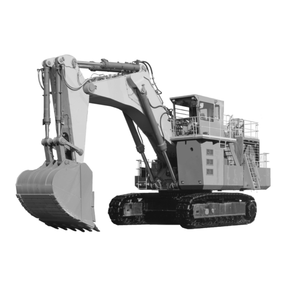
COMPONENTS NAME COMPONENTS NAME Loading Shovel 1- Bucket 10 11 12 2- Bucket Cylinder 3- Arm 4- Level Cylinder 5- Arm Cylinder 6- Boom Cylinder 7- Boom 8- Cab 9- Emergency Escape Device Hanger 10- Emergency Escape Device Case 11- Fuel Tank 12- Radiator·Intercooler M18C-01-038 13- Counterweight... -
Page 44: Handling Ladder/Emergency Escape Device
HANDLING LADDER / EMERGENCY ESCAPE DEVICE USING LADDER Always use ladder (1) when getting on and off the machine. Do not attempt to climb onto or off the machine any other way. CAUTION: Be sure to extend or retract ladder to locked position. -
Page 45: Operating Ladder On The Ground
HANDLING LADDER / EMERGENCY ESCAPE DEVICE OPERATING LADDER ON THE GROUND Extending 1. Pull down chain (4) to release lock. 2. Pull down handle (3) to lower ladder (1) to locked po- sition. Retracting 1. Pull down chain (2) to release lock. 2. -
Page 46: Emergency Escape
HANDLING LADDER / EMERGENCY ESCAPE DEVICE EMERGENCY ESCAPE How to Use Emergency escape device is provided in case (1) at the left outside the cab. 1. Unlock latch (2) on case (1) to open the cover. 2. Hang hook (3) onto the cab upper-left surface hanger (4). -
Page 47: Emergency Exit
HANDLING LADDER / EMERGENCY ESCAPE DEVICE EMERGENCY EXIT If the operator’s cab door should not open in an emergency, escape in the following methods: 1. Open left window (1). Escape through the window. CAUTION: Be sure to wear a safety glasses be- fore breaking the window glass. - Page 48 HANDLING LADDER / EMERGENCY ESCAPE DEVICE If a fire breaks out, evacuate the machine in the following way: 1. Stop the engines by turning emergency engine stop EMERG.STOP switch (5) to the EMERG STOP position if there is time. 2. Pull the pilot control shut-off lever to the LOCK posi- tion.
-
Page 49: Operator's Station
OPERATOR’S STATION CAB FEATURES 1- Left Control Lever/Horn Switch 2- Bucket Close Pedal (For Loading Shovel) 3- Left Travel Pedal 4- Left Travel Lever 5- Right Travel Lever 6- Right Travel Pedal 7- Bucket Open Pedal (For Loading Shovel) 8- Right Control Lever 9- Pilot Control Shut-Off Lever M146-01-002 10- Switch Panels (Right) -
Page 50: Monitor Panel And Switch Panels (Left)
OPERATOR’S STATION MONITOR PANEL AND SWITCH PANELS (LEFT) M146-01-039 1- Monitor Panel 2- Switch Panel 3- FM/AM Radio 4- Ashtray 5- Engine Speed Control Lever... -
Page 51: Monitor Panel
OPERATOR’S STATION MONITOR PANEL 1- Fuel Gauge 2- Hydraulic Oil Temperature Gauge 3- Coolant Temperature Gauge 4- Tachometer 5- Alternator Indicator 6- Pump Transmission Oil Pressure Indicator (Warning) 7- Engine Oil Pressure Indicator (Warning) M146-01-039 8- Overheat Indicator (Warning) 9- Hydraulic Oil Level Indicator (Warning) 10- Fuel Level Indicator 11- Engine Oil Level Indicator 12- Download Indicator... -
Page 52: Fuel Gauge
OPERATOR’S STATION FUEL GAUGE Fuel machine before needle reaches “E”. When the needle reaches “E”, approximately 300 liters (79 US gal) of fuel remain. HYDRAULIC OIL TEMPERATURE GAUGE M117-01-055 Start the engine. Run at slow idle until the needle enters white zone (A). -
Page 53: Alternator Indicator
OPERATOR’S STATION ALTERNATOR INDICATOR Red indicator will light when alternator output is low. Check electrical system. M144-01-023 PUMP TRANSMISSION OIL PRESSURE INDI- CATOR (WARNING) Red indicator will light and buzzer will sound when pump transmission oil pressure is low. Stop the engine immedi- ately. -
Page 54: Hydraulic Oil Level Indicator(Warning)
DOWNLOAD INDICATOR M117-01-048 When the monitoring system (optional) is provided, the green indicator comes ON if the system memory is fully occupied. If the indicator comes ON, download the data. Ask your authorized Hitachi dealer for details. M118-01-012 1-12... -
Page 55: Coolant Level Indicator
OPERATOR’S STATION COOLANT LEVEL INDICATOR When level check switch is pushed, green indicator will light if coolant level is adequate for operation. NOTE: This check does NOT take the place of daily inspection HYDRAULIC OIL LEVEL INDICATOR M117-01-035 When level check switch is pushed, green indicator will light if hydraulic oil level is adequate for operation. -
Page 56: Engine Room Light Indicator
OPERATOR’S STATION ENGINE ROOM LIGHT INDICATOR This indicator will light when the lights in the engine room, in the room under the cab, and in the pump room are ON. ENTRANCE LIGHT INDICATOR M117-01-045 This indicator will light when the entrance lights, located at the cab rear is ON. -
Page 57: Coolant Level Indicator (Warning)
Immediately, set the machine in the safety position and stop the engine. Then, contact your nearest Hitachi dealer. NOTE: When the key switch is turned ON, this indicator normally stays ON until the engine starts. -
Page 58: Engine Exhaust Gas Temperature Indicator
OPERATOR’S STATION ENGINE EXHAUST GAS TEMPERATURE IN- DICATOR (WARNING) If the engine exhaust temperature increases abnormally, the yellow indicator comes ON. Reduce the engine speed to the slow idle speed to lower the exhaust temperature. After the indicator goes OFF, check the exhaust system for any failure. -
Page 59: Stop Valve Indicator (Warning)
OPERATOR’S STATION STOP VALVE INDICATOR (WARNING) Red indicator will light and buzzer will sound when stop valve in the low pressure circuit is closed, and the engine cannot be started. EMERGENCY ENGINE STOP INDICATOR M117-01-041 (WARNING) When the emergency engine stop switch is turned to the EMERG STOP position, red indicator will light and the starter cannot be operated. -
Page 60: Switch Panel
OPERATOR’S STATION SWITCH PANEL M18C-01-020 1- Washer Switch 2- Wiper Delay Selector Switch 3- Cigar Lighter 4- Wiper Switch 5- Air Conditioner Rear Panel 6- Air Conditioner Side Panel 7- Air Conditioner Front Panel 8- Indicator Light Check Switch 9- Level Check Switch 10- Buzzer Stop Switch 11- Dimmer Switch 12- Engine Speed Control Lever... -
Page 61: Wiper Switch
OPERATOR’S STATION WIPER SWITCH Wipers (2) can be operated using wiper switch (1) as fol- lows: OFF position (A): Deactivated INT position (B): Wiper (2) operates intermittently. LO position (C): Wiper (2) continuously operates in slow speed. HI position (D): Wiper (2) continuously operates in fast speed. -
Page 62: Air Conditioners
OPERATOR’S STATION AIR CONDITIONERS This machine is equipped with three air conditioners, all located in the room under the cab. Air flow vents for these air conditioners are located inside the cab at the front, side, and rear, respectively. Moreover, three air conditioner con- trol panels are provided in the cab, each designated for one of the three air conditioners. - Page 63 OPERATOR’S STATION Designations and Functions of Controls 7- Ventilation Shift Switch 8- Air Conditioner Switch 9- Air Conditioner Indicator 10- Temperature Control Switches 11- Temperature Indicator 12- Blower Control Switches 13- Blower Speed Indicator Ventilation Shift Switch (7) Each time ventilation shift switch (7) is pressed, ventila- tion mode is shifted between Circulation Fresh Air...
-
Page 64: Cooling
OPERATOR’S STATION COOLING Set the temperature to the lowest setting using temperature control switch (10). (Repeatedly press temperature control switch (10) until only the leftmost indicator (11) is on.) Press blower control switch (12) to turn on the blower fan. Press air conditioner switch (8). (Air conditioner indica- tor (9) should turn on.) Cool air will flow from the vents. -
Page 65: Dehumidifying And Heating
OPERATOR’S STATION DEHUMIDIFYING AND HEATING (To prevent the windshield from clouding) Set the temperature to the highest setting using tempera- ture control switch (10). (Repeatedly press temperature control switch (10) until all temperature indicators (11) turn on.) Press blower control switch (12) to turn on the blower fan. -
Page 66: Defrosting
OPERATOR’S STATION DEFROSTING Set the temperature to the highest setting using tempera- ture control switch (10). (Repeatedly press temperature control switch (10) until all temperature indicators (11) turn on.) Repeatedly press blower switch (12) to the high speed position (until blower indicator (13) comes on). -
Page 67: Blower Operation Without Cooling Or Heating
OPERATOR’S STATION BLOWER OPERATION WITHOUT COOLING OR HEATING Set the temperature to the lowest setting using temperature control switch (10). (Repeatedly press temperature control switch (10) until only the leftmost indicator (11) is on.) Press blower control switch (12) to turn on the blower fan. -
Page 68: Indicator Light Check Switch
OPERATOR’S STATION INDICATOR LIGHT CHECK SWITCH 1. Turn key switch to the ON position. • Alternator indicator (2), pump transmission oil pres- sure indicator (3),engine oil pressure indicator (4), en- gine stop indicator (5), and engine warning indicator (6) will come ON. If either indicator fails to light, the in- dicator bulb may be burned out. -
Page 69: Level Check Switch
OPERATOR’S STATION LEVEL CHECK SWITCH Turn the key switch to the ON position. When engine oil levels (2), coolant level (3) and hydraulic oil level (4) are adequate for operation, these indicators on the monitor panel will light when level check switch (1) is pushed. -
Page 70: Buzzer Stop Switch
OPERATOR’S STATION BUZZER STOP SWITCH The buzzer will sound in the following cases. 1. Coolant level is low. (Coolant level indicator (2) lights also.) 2. Pump transmission oil pressure is low. (Pump transmission oil pressure indicator (3) lights also.) 3. Engine oil pressure is low. (Engine oil pressure indicator (4) lights also.) M18C-01-023 4. -
Page 71: Dimmer Switch
OPERATOR’S STATION DIMMER SWITCH Use dimmer switch (1) to adjust the air cond. panels (2), grouped pilot lamp (3), fuel gauge (4), hydraulic oil tem- perature gauge (5), coolant temperature gauge (6), ta- chometer (7), and switches (8) illumination. Clockwise Turn: Brighter Illumination Counterclockwise Turn: Darker Illumination M18C-01-023... -
Page 72: Work Light Switch
OPERATOR’S STATION WORK LIGHT SWITCH Press work light switch (1) to turn on all work lights (2). In addition, illumination for air cond. panels (3), fuel gauge (4), hydraulic oil temperature gauge (5), coolant temperature gauge (6), tachometer (7), and radio (8) will be lit. NOTE: Work light (2) will stay ON for approx. -
Page 73: Dome Light Switch
OPERATOR’S STATION DOME LIGHT SWITCH Press dome light switch (1) to turn on dome lights (2) and (3), located on the front and rear parts of the cab ceiling. M18C-01-022 M144-01-033 M144-01-034 1-31... -
Page 74: Engine Room Light Switch
OPERATOR’S STATION ENGINE ROOM LIGHT SWITCH Press engine room light switch (1) to turn on lights (3), (4) and (5) located in the room under the cab, in the engine room, and in the pump room, respectively. Engine room light indicator (2) will also light. NOTE: Engine room lights (3), (4) and (5) will stay ON for approx. -
Page 75: Entrance Light Switch
OPERATOR’S STATION ENTRANCE LIGHT SWITCH Press entrance light switch (1) to turn on entrance light (3). Entrance light indicator (2) will also light. NOTE: Entrance light (3) will stay ON approx. 1 minute go OFF after the key switch is turned OFF with entrance light switch (3) ON. -
Page 76: Travel Speed Switch
OPERATOR’S STATION TRAVEL SPEED SWITCH Fast speed (rabbit) and slow speed (turtle) can be selected by pushing travel speed switch (1). 2- Travel Mode Indicator (Slow Speed) 3- Travel Mode Indicator (Fast Speed) M18C-01-020 M18C-01-024 AUTO-IDLE SWITCH While auto-idle switch (4) is turned on, engine speed de- creases to the auto-idle setting from the engine speed con- trol lever setting approximately 4 seconds after the control levers are returned to neutral. -
Page 77: Switch Panel (Right)
OPERATOR’S STATION SWITCH PANEL (RIGHT) 1- Emergency Engine Stop Switch 2- Key Switch EMERGENCY ENGINE STOP SWITCH M117-01-093 If an emergency engine stop is required or if the engine won’t stop due to a failure of the key switch, turn engine emergency stop switch (1) to the EMERG STOP position from the NORMAL position to stop the engine. -
Page 78: Preheat Switch
OPERATOR’S STATION PREHEAT SWITCH Turn key switch (1) to the ACC position. Open preheat switch cover (2) and press preheat switch (3). Preheat indi- cator (4) comes ON, starting preheating. When preheat switch (3) is pressed again within 30 seconds, the switch is turned OFF and preheat indicator (4) goes OFF, completing START preheating. -
Page 79: Engine Troubleshooting Switch
OPERATOR’S STATION ENGINE TROUBLESHOOTING SWITCH Engine troubleshooting switch is located behind side cover (1) of the left console in the cab. If the engine and/or engine related parts fail, and either en- gine warning indicator (3) or engine stop indicator (4) lights or continues flashing, display fault codes (flashing the en- gine warning indicator) by operating engine troubleshooting switch (2). -
Page 80: Hour Meter
OPERATOR’S STATION HOUR METER 1- Hour Meter The right hand number indicates tenths (six minutes) of an hour. M144-01-033 HORN SWITCH M177-01-057 Horn switch (2) is provided on the top of the left control lever. The horn continuously sounds as long as switch (2) is pressed. -
Page 81: Fm/Am Radio Operation
OPERATOR’S STATION FM/AM RADIO OPERATION 1. Controls on the radio 1- Power Switch/Volume Control Knob 2- Tone Adjustment Ring 3- AM/FM Switch 4- Station Preset 5- Tuning Switch 6- Display Mode Change Switch 7- Digital Display Radio M146-01-039 8- Time Set Switch 9- Set Switch 2. -
Page 82: Digital Clock Setting Procedure
OPERATOR’S STATION 3. Station Presetting Procedure (1) Select the desired station using tuning switches (5). (Refer to the “Tuning Procedure” section.) (2) Press and hold one station preset (4) for more than 2 seconds until an electronic tone is heard. Now, the selected station is preset for the selected sta- tion preset. -
Page 83: Operator's Seat Adjustment
OPERATOR’S STATION OPERATOR’S SEAT ADJUSTMENT Seat Angle and Height Adjustment (1) The rear part of the seat height can be adjusted in 5 positions at 15 mm (0.6 in) intervals. Pull up and hold lever (1) to adjust the height of the rear part of the seat, thus adjusting the angle of the seat setting in the rear part. - Page 84 OPERATOR’S STATION Seat Fore-Aft Adjustment Pull up and hold handle (3) to unlock the seat for the seat fore-aft adjustment. With handle (3) pulled up and held, slide the seat to the desired distance from the control levers. 17 posi- tions at 10 mm (0.4 in) intervals (160 mm (6.3 in) range) are provided for the seat fore-aft adjustment.
-
Page 85: Seat Belt
OPERATOR’S STATION SEAT BELT CAUTION: Be sure to use the seat belt when op- erating the machine. Before operating the machine, be sure to examine seat belt (1), buckle (2), or attaching hardware. Replace seat belt (1), buckle (2), or attaching hardware if they are damaged, or worn. -
Page 86: Cab Door Release Button
OPERATOR’S STATION CAB DOOR RELEASE BUTTON When opening the cab door, lock it in the fully opened posi- tion. Open the door all the way until it locks in the latch on the side of the cab. Push button (1) to unlock the door. OPENING CAB LEFT WINDOW The cab left window can be opened. -
Page 87: Break-In
BREAK-IN OBSERVE MACHINE CLOSELY IMPORTANT: 1. Be extra cautious during the first 50 hours, until you become thoroughly familiar with the sound and feel of your new machine. 2. Do not attempt to travel the machine at full speed before the break-in pe- riod is over, as the lower rollers and front idlers may seize. -
Page 88: After The First 50 Hours
BREAK-IN AFTER THE FIRST 50 HOURS 1. Check coolant, engine oil, and hydraulic oil level and for leaks every day. Refill with the recommended oils and coolant. 2. Check and grease the greasing points at the regular intervals. Grease the front attachment pins every day. 3. -
Page 89: Operating The Engine
OPERATING THE ENGINE Level Cylinder INSPECT MACHINE DAILY BEFORE STARTING Boom Loading Shovel Front Attachment Boom Cylinder Bucket Backhoe Front Attachment Arm Cylinder Cylinder Bucket Boom Cylinder Dump Cylinder Bucket Cylinder Cylinder M18C-01-040 Boom Lubricator Swing Device Center Joint Fuel Tank Battery Link B Hydraulic Oil Tank... -
Page 90: Check Instruments Before Starting
OPERATING THE ENGINE CHECK INSTRUMENTS BEFORE STARTING 1. Place pilot control shut-off lever (1) in the LOCK posi- tion. 2. Check that all control levers are in neutral. 3. Indicator Light Check (1) Turn key switch (2) ON. Alternator indicator (4), pump transmission oil pressure indicator (5), en- gine oil pressure indicator (6), and engine stop in- dicator (7) will come ON. -
Page 91: Level Check
OPERATING THE ENGINE LEVEL CHECK 1. Turn key switch to the ON position. 2. Depress level check switch (1). Hydraulic oil level (4), coolant levels (3) and engine oil levels (2) indicators will light if levels are adequate for operation. IMPORTANT: Prevent possible machine damage. -
Page 92: Starting The Engine
OPERATING THE ENGINE STARTING THE ENGINE 1. Pull pilot control shut-off lever (1) up to the LOCK po- sition. 2. Move the engine speed control lever (2) to the LOW position. 3. Turn key switch (3) to the ON position. 4. -
Page 93: Starting In Cold Weather
OPERATING THE ENGINE STARTING IN COLD WEATHER Follow these procedures if the engine is difficult to start in the usual starting method. Preheating 1. Turn key switch (1) to the ACC position. 2. Open preheat switch cover (4). Turn preheat switch START (3) ON. - Page 94 OPERATING THE ENGINE 4. As soon as the engine starts, release key switch (1). The key will automatically return to the ON position. 5. Close preheat switch cover (4). IMPORTANT: Preheating uses a large amount of cur- rent so that the batteries will be quickly discharged if preheating is frequently performed.
-
Page 95: Check Instruments After Starting
OPERATING THE ENGINE CHECK INSTRUMENTS AFTER STARTING IMPORTANT: If indicator lights do not go out after starting engine, IMMEDIATELY STOP THE ENGINE and correct the cause. Check that 1. Hydraulic oil temperature gauge (1) is in the green or white zone. 2. -
Page 96: Using Booster Batteries
OPERATING THE ENGINE USING BOOSTER BATTERIES CAUTION: 1. An explosive gas is produced while batteries are in use or being charged. Keep flames or sparks away from the battery area. Charge the batteries in a well ventilated area. Do not continue to use or charge the battery when electrolyte level is lower than specified. - Page 97 OPERATING THE ENGINE Disconnecting the booster batteries Connecting the Booster Batteries 1. Disconnect black negative (–) cable from machine frame (4) first. 2. Disconnect the other end of black negative (–) cable Upper from booster batteries (3). 3. Disconnect red positive (+) cable from booster batter- ies (2).
-
Page 98: Stopping The Engine
OPERATING THE ENGINE STOPPING THE ENGINE IMPORTANT: Prevent possible engine damage. If engine stops when operating load, remove load. Restart engine immediately. Run 30 seconds at half speed before adding load. 1. Park the machine on a level surface. M18C-01-020 2. -
Page 99: Emergency Engine Stop Switch
OPERATING THE ENGINE EMERGENCY ENGINE STOP SWITCH IMPORTANT: Normally, use the key switch to stop the engine after running the engine at slow NORMAL idle for five minutes. Use the emergency EMERG. STOP engine stop switch only for emergency stops, or if the key switch malfunctions. If the engine is shut off, without cooling down, the turbocharger free-wheels without receiving lubricant, resulting in... -
Page 100: Engine Stoop Switches
OPERATING THE ENGINE ENGINE STOP SWITCHES Engine stop switches (1) are located as follows to ensure safe inspection work in the engine compartment. Engine Compartment: Two Pump, Compartments: Two When engine stop switch (1) is turned to the EMERG. STOP position, the engine won’t be started with key switch. Engine emergency stop indicator (2) will come ON at this time. -
Page 101: Driving The Machine
DRIVING THE MACHINE DRIVE THE MACHINE CAREFULLY IMPORTANT: During freezing weather, park machine on a hard surface to prevent tracks from freezing to the ground. Clean debris from tracks and track frame. If tracks are frozen to the ground, raise tracks using boom, move machine care- fully to prevent damage to drive train and tracks. -
Page 102: Steering The Machine Using Pedals
DRIVING THE MACHINE STEERING THE MACHINE USING PEDALS CAUTION: In the standard travel position, the idlers are positioned at the front of the machine Front Idler and the travel motors at the rear. If the travel mo- tors are positioned at the front of the machine, the control actions of the travel pedals will be re- versed. -
Page 103: Steering The Machine Using Levers
DRIVING THE MACHINE STEERING THE MACHINE USING LEVERS CAUTION: In the standard travel position, the idlers are positioned at the front of the machine Front Idler and the travel motors at the rear. If the travel mo- tors are positioned at the front of the machine, the control actions of the travel levers will be re- versed. -
Page 104: Travel Speed Switch
DRIVING THE MACHINE TRAVEL SPEED SWITCH CAUTION: Tipping accidents can cause serious personal injury. Do not change travel mode while traveling; especially, changing speed to the fast mode when descending slopes will create a very dangerous situation. Always stop the machine before changing the travel mode speed. -
Page 105: Travel Alarm
DRIVING THE MACHINE TRAVEL ALARM The travel alarm functions to alert bystanders when the machine is traveling. CAUTION: If the travel alarm does not sound when the travel levers or pedals are operated, immediately stop the engine and contact your authorized dealer for repair. -
Page 106: Traveling
DRIVING THE MACHINE TRAVELING CAUTION: Use a signal person when moving, swinging or operating the machine in congested areas. Coordinate hand signals before starting the machine. • Be sure to fully pull up the ladder before traveling. • Before moving machine, determine which way to move travel pedals/levers for the direction you want to go. -
Page 107: Operating On Soft Ground
DRIVING THE MACHINE OPERATING ON SOFT GROUND Boom • Avoid traveling on very soft ground that does not have sufficient strength to firmly support the machine. • If the machine is operated on very soft ground or be- comes stuck, it may be necessary to clean the track 90 to 110°... -
Page 108: Towing Machine A Short Distance
DRIVING THE MACHINE TOWING MACHINE A SHORT DISTANCE RIGHT CAUTION: Cables, straps, or ropes can break causing serious injury. Do not tow machine with damaged chains, frayed cables, slings, straps, or Protector wire ropes. Always wear gloves when handling cable, straps or wire ropes. -
Page 109: Operating In Water Or Mud
DRIVING THE MACHINE OPERATING IN WATER OR MUD The machine can be operated in water up to the upper edge of the upper rollers only if worksite footing has suffi- cient strength to prevent the machine from sinking past the upper edge of the upper roller, and only if the water is flow- ing slowly. -
Page 110: Precautions For Traveling On Slopes
DRIVING THE MACHINE PRECAUTIONS FOR TRAVELING ON SLOPES CAUTION: Avoid possible injury from traveling on slopes. Tipping over or skidding down of the machine may result. Thoroughly read and under- stand precautions below and be sure to travel at slow speed on slopes. Never attempt to travel on 0.5 to 1.0 m slopes with the bucket loaded or any load sus- (1′8″... -
Page 111: Parking The Machine On Slopes
DRIVING THE MACHINE PARKING THE MACHINE ON SLOPES CAUTION: Avoid parking machine on slopes. The machine may tip over, possibly resulting in per- sonal injury. If parking the machine on a slope is unavoidable: • Thrust the bucket teeth into the ground. •... - Page 112 DRIVING THE MACHINE MEMO ..............................................................................................................................................................................................................................................................................................................................................................................................................................................................................................................................................................................................................................................................................................................................................................................................................................................................................................................................................................................................................................................................................................................................4-12...
-
Page 113: Operating The Machine
OPERATING THE MACHINE CONTROL LEVER (HITACHI PATTERN BACKHOE) CAUTION: Never place any part of body beyond window frame. It could be crushed by the boom if boom control lever is accidentally bumped or otherwise engaged. If window is missing or bro- ken, replace immediately. -
Page 114: Control Lever (Iso Pattern Backhoe)
OPERATING THE MACHINE CONTROL LEVER (ISO PATTERN BACKHOE) CAUTION: Never place any part of body beyond window frame. It could be crushed by the boom if boom control lever is accidentally bumped or otherwise engaged. If window is missing or bro- ken, replace immediately. -
Page 115: Control Lever (Hitachi Pattern Loading Shovel)
OPERATING THE MACHINE CONTROL LEVER (HITACHI PATTERN LOADING SHOVEL) CAUTION: Never place any part of body beyond window frame. It could be crushed by the boom if boom control lever is accidentally bumped or otherwise engaged. If window is missing or bro- ken, replace immediately. -
Page 116: Control Lever (Iso Pattern Loading Shovel)
OPERATING THE MACHINE CONTROL LEVER (ISO PATTERN LOADING SHOVEL) CAUTION: Never place any part of body beyond window frame. It could be crushed by the boom if boom control lever is accidentally bumped or otherwise engaged. If window is missing or bro- ken, replace immediately. -
Page 117: Bucket Open-Close Pedals (Loading Shovel)
OPERATING THE MACHINE BUCKET OPEN-CLOSE PEDALS (LOADING SHOVEL) 9 − Bucket Closing 10 − Bucket Opening M146-01-010 M117-05-031... -
Page 118: Pilot Control Shut-Off Lever
OPERATING THE MACHINE PILOT CONTROL SHUT-OFF LEVER Pilot control shut-off lever (1) functions to prevent misoperation of the machine from occurring if the control levers are accidentally moved when leaving the operator's seat or when entering the cab. CAUTION: 1. Always pull pilot control shut-off lever (1) into the full LOCK position. -
Page 119: Warming-Up Operation
OPERATING THE MACHINE Warming-up Operation Green Zone IMPORTANT: The proper machine operating hydraulic oil temperature is 50 to 80 ° ° ° ° C corre- sponding to the green zone of the hy- draulic oil temperature gauge on the monitor panel. If the machine is operated excessively when the oil temperature is lower than 20 °... -
Page 120: Warming-Up The Motor And The Cylinders
OPERATING THE MACHINE Warming-up the Motor and the Cylinders IMPORTANT: 1. In cold weather, be sure to thoroughly warm-up the motors and cylinders. 2. If the hydraulic circuit is continuously relieved for a certain amount of time, the temperature in the control valve would rise excessively. -
Page 121: Auto-Idle
OPERATING THE MACHINE AUTO-IDLE With auto-ilde switch (1) turned on, approximately 4 sec- onds after all control levers are returned to neutral, the en- gine speed decreases to the auto-idle setting to save fuel consumption. The engine speed will immediately increase to the speed set by engine speed control lever (2) when any control lever is operated. -
Page 122: Engine Speed Control
OPERATING THE MACHINE ENGINE SPEED CONTROL Increase and decrease the engine speed using engine speed control lever (1) located on the left console, as illus- trated. Slow Idle : Move lever (1) to the LOW position (2) Fast Idle : Move lever (1) to the HIGH position (3) •... -
Page 123: Precautions For Operations
OPERATING THE MACHINE PRECAUTIONS FOR OPERATIONS CAUTION: Investigate the work site before start- ing operations. 1. Be sure to install an overhead cab guard when operating in a work site which has a possibil- ity of falling objects. 2. If operation on soft ground is required, suffi- ciently reinforce the ground beforehand. -
Page 124: Operate The Machine Safely
OPERATING THE MACHINE OPERATE THE MACHINE SAFELY CAUTION: Prevent the machine from tipping over and from being involved in a ground col- lapse. Take the necessary precautions as follows: 1. Make sure the worksite has sufficient strength to firmly support the machine. When working close to an excavation or at road shoulders, operate the machine with the tracks positioned perpendicular to the cliff... -
Page 125: Operating Backhoe
OPERATING THE MACHINE OPERATING BACKHOE 100 mm (4 in) 100 mm (4 in) 1. Place the bucket teeth on the ground with the bottom of the bucket at a 45 degree angle to the ground. 2. Pull the bucket toward the machine using the arm as the main digging force. -
Page 126: Avoid Abusive Operation
OPERATING THE MACHINE AVOID ABUSIVE OPERATION WRONG Do not use travel as an additional digging force. Severe machine damage may result. Do not raise rear of machine to use the machine’s weight as additional digging force. Severe machine damage may result. -
Page 127: Operating Tips
OPERATING THE MACHINE OPERATING TIPS WRONG Do not hit the track with the bucket when digging. Whenever possible, position your machine on a level sur- face. Do not use the bucket as a hammer or pile driver. Do not attempt to shift rocks and break walls using swing motion. IMPORTANT: To avoid damaging cylinders, do not strike the ground with the bucket nor use the bucket for tamping with the bucket... -
Page 128: Loading Shovel Operation
OPERATING THE MACHINE LOADING SHOVEL OPERATION 1. To dig, position the bucket bottom parallel to and touching the ground and extend the arm while crowd- ing the bucket. 2. Digging force increases as the arm is extended. Try to dig with the arm extended where strong digging forces are required. - Page 129 OPERATING THE MACHINE 3. Do not use the rear of the bucket for grading opera- WRONG tion, as this will damage it. M117-05-019 WRONG 4. Do not push rocks or other heavy materials with the side of the bucket (using the swing movement of the upperstructure), as this may damage the front at- tachment.
- Page 130 OPERATING THE MACHINE 5. Do not use the weight of the base machine to pry WRONG earth as illustrated. Doing so will damage the base machine and may cause personal injury. M117-05-009 6. Machine stability is greater when the load is posi- tioned parallel with the tracks.
-
Page 131: Object Handling
OPERATING THE MACHINE OBJECT HANDLING --- IF EQUIPPED CAUTION: When you use machine for object handling, be sure to comply with all local regula- tions. Cables, straps, or ropes can break, causing seri- ous injury. Do not use damaged chains, frayed cables, slings, straps, or ropes to crane. -
Page 132: Overnight Storage Instructions
OPERATING THE MACHINE OVERNIGHT STORAGE INSTRUCTIONS 1. After finishing the day’s operation, drive the machine to a firm, level ground where no possibility of falling stones, ground collapse, or floods. Park the machine referring to the “PARKING THE MACHINE” in the “DRIVING THE MACHINE”... -
Page 133: Maintenance
Use only genuine HITACHI parts. Failure to use recommended fuel, lu- bricants, and genuine Hitachi parts will result in loss of Hitachi product warranty. Never adjust engine governor or hy- draulic system relief valve. Protect electrical parts from water and steam. -
Page 134: Service Your Machine At Specified Intervals
SHORTER INTERVALS. M144-01-033 USE CORRECT FUELS AND LUBRICANTS IMPORTANT: Always use recommended fuels and lu- bricants. Failure to do so will result in machine damage and loss of Hitachi product war- ranty. -
Page 135: Prepare Machine For Maintenance
MAINTENANCE PREPARE MACHINE FOR MAINTENANCE Before performing the maintenance procedures given in the following chapters, park the machine as described be- low, unless otherwise specified. 1. Park the machine on a level surface. 2. Lower the bucket to the ground. 3. - Page 136 MAINTENANCE 9. Before starting to check and/or service the inside of the engine compartment, turn engine stop switch (3) located at the engine compartment entrance to the EMERG. STOP position to assure safety. 10. When using a vacuum pump to create negative pres- sure in the hydraulic oil tank while working on the hy- draulic lines, close stop valve cock (4) on the hydrau- lic oil tank air bleed valve.
-
Page 137: Open Access Doors For Service
MAINTENANCE OPEN ACCESS DOORS FOR SERVICE CAUTION: 1. Do not keep the access doors open when the machine is parked on a slope, or while the wind is blowing hard. The access doors may close accidentally, possibly resulting in per- sonal injury. -
Page 138: Inspection/Maintenance Lights
MAINTENANCE INSPECTION/MAINTENANCE LIGHTS A light is provided for inspection/maintenance work in room (1) under the cab, in engine room (2) and in pump room (3). Use engine room light switch (4), located on the switch panel in the cab, to turn on/off these lights. In Room Under the Cab M141-01-017 In Engine Room... -
Page 139: Use A Chain To Prevent Falling Accidents
MAINTENANCE USE A CHAIN TO PREVENT FALLING ACCI- DENTS When inspection or maintenance is required on cab front step (2), tighten chain (1) as described below to prevent falling from cab front step (2). CAUTION: Before starting inspection or mainte- nance on the cab front step, be sure to attach the chain to the step handrail. - Page 140 MAINTENANCE MEMO ..........................................................................................................................................................................................................................................................................................................................................................................................................................................................................................................................................................................................................................................................................................................................................................................................................................................................................................................................................................................................................................................................................................
-
Page 141: Construction Outline
MAINTENANCE CONSTRUCTION OUTLINE Loading Shovel Front Attachment Level Cylinder Boom Boom Cylinder Bucket Bucket Dump Cylinder Cylinder Cylinder M18C-01-040 Backhoe Front Attachment Arm Cylinder Boom Cylinder Bucket Cylinder Boom Swing Device Lubricator Center Joint Fuel Tank Battery Link B Hydraulic Oil Tank Link A Air Cleaner Bucket... -
Page 142: Hydraulic System
MAINTENANCE HYDRAULIC SYSTEM IMPORTANT: Hydraulic equipment such as hydraulic pumps, control valves, and relief valves have been adjusted at the factory. Do not attempt to disassemble or turn the ad- justing screws, as they are very difficult to readjust. Consult your authorized dealer if any trouble should occur. - Page 143 MAINTENANCE Loading Shovel BUCKET CYLINDER DUMP CYLINDER ARM CYLINDER BOOM CYLINDER LEVEL CYLINDER BUCKET CLOSE PEDAL BUCKET OPEN PEDAL TRAVEL PILOT VALVE LEFT PILOT VALVE RIGHT PILOT VALVE PILOT SHUT-OFF VALVE AIR-CON. COMP. MOTOR ACCUMULATOR CHECK VALVE SWING MOTOR CENTER JOINT CONTROL VALVE: LEFT TRAVEL CONTROL VALVE: BUCKET OPEN AND CLOSE...
- Page 144 MAINTENANCE Backhoe BUCKET CYLINDER ARM CYLINDER BOOM CYLINDER TRAVEL PILOT VALVE LEFT PILOT VALVE RIGHT PILOT VALVE PILOT SHUT-OFF VALVE AIR-CON. COMP. MOTOR ACCUMULATOR CHECK VALVE SWING MOTOR CENTER JOINT CONTROL VALVE: LEFT TRAVEL CONTROL VALVE: BUCKET CONTROL VALVE: BOOM CONTROL VALVE: ARM CONTROL VALVE: RIGHT TRAVEL CONTROL VALVE: SWING...
-
Page 145: Periodic Replacement Of Rubber Hoses
In order to avoid serious personal injury, be sure to replace the hoses listed in the following table every two years, or 8000 hours of operation, whichever comes first. Use genuine Hitachi parts. M18C-07-058 It is very difficult to gauge the extent of deteriora- tion due to aging, fatigue, and abrasion of rubber hoses by inspection alone. - Page 146 MAINTENANCE Hoses Q’ty in Use Transmission Oil Cooler Hose (5) M18C-07-062 7-14...
- Page 147 MAINTENANCE Hoses Q’ty in Use Loading Shovel Main Frame to Front Hoses Boom M144-07-133 Hoses Q’ty in Use Backhoe Front Main Frame to Hoses Boom M144-07-134 7-15...
- Page 148 MAINTENANCE Fuel Hoses Hoses Q’ty in Use Fuel Tank to Water Separator Filter (a) Water Separator to Engine (b) Engine to Fuel Tank (c) M18C-07-007 M18C-07-008 M18C-07-045 7-16...
-
Page 149: Maintenance Interval Guide
MAINTENANCE MAINTENANCE INTERVAL GUIDE A. GREASING (See Page 7-21) Interval (hours) Parts Quantity 500 1000 1500 2000 1. Loader Front Joint Bucket Pins 8 ✱ Pins Other Front Pins 11 ✱ Bucket and Link Pins 2. Backhoe Front Joint 22 ✱ Pins Other Front Pins 14 ✱... - Page 150 MAINTENANCE D. HYDRAULIC SYSTEM (See Page 7-46) Interval (hours) Parts Quantity 2000 2500 4000 12000 1. Check Hydraulic Oil Level 2. Drain Hydraulic Oil Tank Sump 2200 L 3. Change Hydraulic Oil (580 US gal) Replace Full-Flow Filter and Drain Filter 5.
- Page 151 3. Clean Radiator Core 4. Clean Intercooler Core NOTE: ✱ Before leaving the Hitachi factory, the cooling system is filled with a mixture of water and Genuine Hitachi Long-Life Coolant. As long as Genuine Hitachi Long-Life Coolant is used, the service inter- vals between changing the coolant is once every two years, or every 4000 hours, whichever comes first.
- Page 152 MAINTENANCE I. ELECTRICAL SYSTEM (See Page 7-88) J. MISCELLANEOUS (See Page 7-99) Interval (hours) Parts Quantity 1000 1500 3000 1. Check Bucket Teeth for Wear and Looseness 2. Inspect Emergency Rope and Rope Mounting Hardware 3. Check Auto-Lubrication System Check 4.
-
Page 153: Greasing
MAINTENANCE A. GREASING Interval (hours) Parts Quantity 500 1000 1500 2000 1. Loader Front Joint Bucket Pins 8 ✱ Pins Other Front Pins 11 ✱ Bucket and Link Pins 2. Backhoe Front Joint 22 ✱ Pins Other Front Pins 14 ✱ 3. -
Page 154: Loading Shovel Front Joint Pins
MAINTENANCE Loading Shovel Front Joint Pins --- daily (every 10 hours) Add grease to all fittings shown below daily. Most of the fittings are grouped, as shown, for quick and safe lubrication. • Bucket Cylinder Bottom Pin (1) M114-07-008 • Dump Cylinder Bottom Pin (2) M144-07-002 •... - Page 155 MAINTENANCE 2. Grouped Grease Fittings (5) --- Boom : Lubrication M144-07-070 M144-07-078 3. Boom Cylinder Rod Pins (6) M18C-01-001 7-23...
- Page 156 MAINTENANCE 4. Grouped Grease Fittings (7) --- Arm :Lubrication M144-07-005 M144-07-079 7-24...
-
Page 157: Backhoe Front Joint Pins
MAINTENANCE Backhoe Front Joint Pins --- daily Add grease to all fittings shown below daily. Most of the fittings are grouped, as shown, for quick and safe lubrica- tion. 1. Grease Fittings for bucket and link pins. M144-07-081 M144-07-082 7-25... - Page 158 MAINTENANCE • Grease Fittings for Bucket and Link Pins. (Auto-lubrication system equipped) VIEW A VIEW B M18C-07-072 7-26...
- Page 159 MAINTENANCE 2. Grouped Grease Fittings (1) --- Boom/Arm Fittings for boom foot pins and boom cylinder rod pins. M18C-07-009 3. Boom Cylinder Rod Pin (2) M18C-01-001 7-27...
-
Page 160: Swing Bearing
MAINTENANCE Swing Bearing --- every 250 hours (Grouped Grease Fittings --- Main Frame) NOTE: Auto-lubrication can be used for the fittings on the swing bearing. CAUTION: Lubricating both the swing bearing and gear and rotating the upperstructure must be done by one person. Before you lubricate the swing bearing, clear the area of all persons. -
Page 161: Swing Internal Gear
MAINTENANCE Swing Internal Gear --- every 2000 hours CAUTION: Adding or changing swing internal gear grease and rotating the upperstructure must be done by one person. Before you start, clear the area of all persons. Each time you leave the cab •... -
Page 162: Center Joint
MAINTENANCE Center Joint --- every 500 hours (Grouped Grease Fittings --- Main Frame) NOTE: Auto-lubrication can be used for the fittings on the center joint. Each time you leave the cab • • • • Lower the bucket to the ground. •... -
Page 163: Operating The Lubricator
MAINTENANCE OPERATING THE LUBRICATOR The machine is equipped with hose reel and the lubrica- tor, including the grease pump. This device is used for adding grease to the grouped fittings on the main frame and front attachment. Greasing IMPORTANT: Run the engine at medium or higher speed whenever the lubricator is used. - Page 164 MAINTENANCE Replacing Grease When the grease can is empty, replace it following the procedure shown below. 1. Remove wing nuts (7) to remove cover assembly (6) from the grease can. 2. Remove follower plate (8) from the grease can. Replace the grease can with a new one. 3.
-
Page 165: Engine
MAINTENANCE B. ENGINE Interval (hours) Parts Quantity 4000 1000 1500 2000 - 6000 1. Engine Oil Check Oil Level 172 L 2. Engine Oil Change (45.4 US gal) 3. Replace Engine Oil Main Filter 4. Replace Engine Oil Bypass Filter 5. -
Page 166: Engine Oil Level
MAINTENANCE Replenish Engine Oil CAUTION: • Shut down the engine when fueling. Do not smoke while fueling ─ ─ ─ ─ or when handling fuel containers. • Fuel leaked or spilled onto hot surfaces or electri- cal components can cause a fire. •... -
Page 167: Change Engine Oil
MAINTENANCE Change Engine Oil --- every 500 hours Replace Engine Oil Main and Bypass Filters --- every 500 hours 1. Run the engine to warm oil. DO NOT run the engine until oil is hot. 2. Park the machine on a level surface. 3. -
Page 168: Check Alternator Belt Tension
MAINTENANCE 15. Fill the filters with lubricating oil to prevent crankshaft or bearing damage. Apply a light even coat of lubricat- ing oil to the gasket sealing surface prior to installing the filters. 16. Position element to the filter head. Tighten by hand until the seal touches the filter head. -
Page 169: Check Injection Nozzle
MAINTENANCE Check Injection Nozzle --- every 2 000 hours See your authorized dealer. Inspect Bolts and Nuts Outside Engine --- every 2 000 hours (first time after 50 hours) See your authorized dealer. Inspect and Adjust Valve Clearance --- every 2 000 hours See your authorized dealer. -
Page 170: Transmission
MAINTENANCE C. TRANSMISSION Interval (hours) Parts Quantity 500 1000 1500 2000 Check Oil Level 1. Pump Change Oil 26 L (6.9 US gal) Trans- Engine mission Replace Filter Gear Clean Breather Check Oil Level 2. Swing Gear Reduction Change Oil 67 L (17.7 US gal)×2 Gear Clean Breather... - Page 171 MAINTENANCE Pump Transmission Check Oil Level --- every 50 hours (first time after 10 hours) 1. Park the machine on a level surface. 2. Lower the bucket to the ground. 3. Turn the auto-idle switch off. IMPORTANT: The turbocharger may be damaged if the engine is not properly shut down.
- Page 172 MAINTENANCE Change Oil --- every 500 hours (first time after 50 hours) 1. Park the machine on a level surface. 2. Lower the bucket to the ground. 3. Turn the auto-idle switch off. IMPORTANT: The turbocharger may be damaged if the engine is not properly shut down.
- Page 173 MAINTENANCE Replace Filter --- every 500 hours 1. Unscrew cartridge filter (4) from the filter head, dis- card the cartridge filter. 2. Fill the filter with oil. Apply a light even coat of lubricat- ing oil to the gasket sealing surface prior to installing the cartridge filter.
- Page 174 MAINTENANCE Swing Reduction Gear Check Oil Level --- every 50 hours (first time after 10 hours) 1. Park the machine on a level surface. 2. Lower the bucket to the ground. 3. Turn the auto-idle switch off. IMPORTANT: The turbocharger may be damaged if the engine is not properly shut down.
- Page 175 MAINTENANCE Change Gear Oil --- every 1000 hours (first time after 50 hours) 1. Park the machine on a level surface. 2. Lower the bucket to the ground. 3. Turn the auto-idle switch off. IMPORTANT: The turbocharger may be damaged if the engine is not properly shut down.
-
Page 176: Travel Reduction Gear
MAINTENANCE Travel Reduction Gear Check Oil Level --- every 250 hours 1. Park the machine on a level surface. 2. Lower the bucket to the ground. 3. Turn the auto-idle switch off. IMPORTANT: The turbocharger may be damaged if the engine is not properly shut down. - Page 177 MAINTENANCE Change Gear Oil --- every 2000 hours (first time after 500 hours) 1. Park the machine on a level surface. 2. Lower the bucket to the ground. 3. Turn the auto-idle switch off. IMPORTANT: The turbocharger may be damaged if the engine is not properly shut down.
-
Page 178: Hydraulic System
–10 to 50°C Temp. (–4 to 122°F) (14 to 122°F) (–4 to 122°F) (14 to 122°F) (–4 to 122°F) (14 to 122°F) Manufacturer Hitachi Super EX 46HN Idemitsu Kosan Super Hydro 46 WRHU British Petroleum Bartran HV46 Rando Oil Caltex Oil HD46 Rando Oil Texaco INC. -
Page 179: Inspection And Maintenance Of Hydraulic Equipment
MAINTENANCE INSPECTION AND MAINTENANCE OF HYDRAULIC EQUIPMENT CAUTION: During operation the parts of the hydraulic system become very hot. Allow the machine to cool down before be- ginning inspection or maintenance. 1. Be sure that the machine is parked on a level, firm surface before servicing hydraulic equipment. - Page 180 MAINTENANCE 7. When connecting hydraulic hoses and pipes, take special care to keep seal surfaces free from dirt and A couple of threads left unwrapped to avoid damaging them. Keep these precautions in mind: Wash hoses, pipes, and the tank interior with a washing liquid and thoroughly wipe it out before reconnecting them.
- Page 181 MAINTENANCE Check Hydraulic Oil Level --- daily IMPORTANT: Never run the engine without oil in hy- draulic oil tank. 1. Park the machine on a level surface. M142-07-093 2. Position the machine with the front attachment posi- tioned as illustrated on the right. 3.
- Page 182 MAINTENANCE Drain Hydraulic Oil Tank Sump --- every 250 hours IMPORTANT: Never run the engine without oil in hy- draulic oil tank. 1. Park the machine on a level surface with the upper- structure rotated 90° for easier access. 2. Lower the bucket to the ground. 3.
- Page 183 MAINTENANCE Change Hydraulic Oil --- every 4000 hours, 2500 hours or 2000 hours IMPORTANT: Hydraulic oil changing intervals differ according to kind of hydraulic oils used. (See Recommended Oil Chart in this group) CAUTION: Hydraulic oil may be hot. Wait for oil M142-07-092 to cool before starting work.
- Page 184 MAINTENANCE 15. Remove drain plug (2) and loosen drain valve (3). Allow oil to drain. 16. Remove drain plug (6) to drain water and sediment completely. 17. Tighten drain plug (6). 18. Tighten drain valve (3). 19. Clean, install and tighten drain plug (2). 20.
- Page 185 MAINTENANCE Air Bleeding Procedures Bleeding Air from Pump IMPORTANT: If the hydraulic pump is not filled with oil, it will be damaged when the engine is started. 1. Loosen hoses (7) and (8) on the pump to release trapped air. Retighten hoses (7) and (8) after oil flows from the pump.
-
Page 186: Replace Full-Flow Filter And Drain Filter
MAINTENANCE Replace Full-Flow Filter and Drain Filter --- every 500 hours (first time after 50 hours) 1. Park the machine on a level surface. 2. Lower the bucket to the ground as illustrated. 3. Turn the auto-idle switch off. M142-07-093 IMPORTANT: The turbocharger may be damaged if the engine is not properly shut down. - Page 187 MAINTENANCE NOTE: There is spring tension under the cover. Hold down the cover when removing last two bolts. 11. Hold down filter cover (2) against light spring load when removing the last two bolts. Remove filter cover (2). 12. Remove spring (5), valve (6), and element (7). 13.
-
Page 188: Replace Pilot Oil Filter
MAINTENANCE Replace Pilot Oil Filter --- every 500 hours (first time after 50 hours) 1. Park the machine on a level surface. 2. Lower the bucket to the ground as illustrated. 3. Turn the auto-idle switch off. M142-07-093 IMPORTANT: The turbocharger may be damaged if the engine is not properly shut down. - Page 189 MAINTENANCE 12. Remove bolts (2). Hold down filter cover (4) when removing last two bolts. NOTE: There is spring tension under filter cover (4). Hold down filter cover (4) when removing last two bolts (2). 13. Remove spring (5), valve (6), O-ring (7) and filter element (8) from filter housing (9).
-
Page 190: Suction Filter
MAINTENANCE Suction Filter Cleaning Suction Filter --- when replacing hydraulic oil Six unit suction filters are provided in the hydraulic oil tank. Clean them when replacing hydraulic oil. CAUTION: Sufficiently ventilate before entering the hydraulic oil tank after draining hydraulic oil. 1. - Page 191 MAINTENANCE Replace Suction Filter --- every 12000 hours Six unit suction filters are provided in the hydraulic oil tank. Clean them when replacing hydraulic oil. Replace all suc- tion filters. CAUTION: Sufficiently ventilate before entering the hydraulic oil tank after draining hydraulic oil. 1.
-
Page 192: Replace High-Pressure Strainer
MAINTENANCE Replace High-Pressure Strainer --- every 12000 hours 1. Park the machine on a level surface. 2. Lower the bucket to the ground. 3. Turn the auto-idle switch off. IMPORTANT: The turbocharger may be damaged if the engine is not properly shut down. 4. -
Page 193: Clean Oil Cooler Core
MAINTENANCE Clean Oil Cooler Core --- every 500 hours CAUTION: Wear safety glasses or goggles when using compressed air. IMPORTANT: High pressure air or water can damage the cooler core fins. Use air pressure [ [ [ [ 0.2 ) or less] ] ] ] and keep the MPa (2 kgf/cm nozzle more than 500 mm away from the core surface. -
Page 194: Check Hoses And Lines
MAINTENANCE Check Hoses and Lines --- daily --- every 250 hours CAUTION: Escaping fluid under pressure can penetrate the skin causing serious injury. To avoid this hazard, search for leaks with a piece of cardboard. Take care to protect hands and body from high- pressure fluids. - Page 195 (Use proper bend radius) Hose ends and Deformation or Replace M115-07-148 fittings Corrosion (10) NOTE: Refer to the illustrations in Fig.1 for each check point location or for a descrip- tion of the abnormality. Use genuine Hitachi parts. M115-07-149 Fig.1 7-63...
- Page 196 Clamps Missing Replace Deformation Replace NOTE: Refer to the illustrations in Fig.2 for each check point location or for a descrip- tion of the abnormality. Use genuine Hitachi parts. Table 3. Oil cooler Interval(hours) Check Points Abnormalities Remedies Every 250 hours...
-
Page 197: Service Recommendations For Hydraulic Fittings
MAINTENANCE SERVICE RECOMMENDATIONS FOR HY- DRAULIC FITTINGS Two hydraulic fitting designs are used on this machine. Flat Face O-ring Seal Fitting (ORS Fitting) An O-ring is used on the sealing surfaces to prevent oil leakage. M104-07-033 1. Inspect fitting sealing surfaces (6). They must be free of dirt or defects. - Page 198 MAINTENANCE Metal Face Seal Fittings Fittings are used on smaller hoses and consist of a metal flare and a metal flare seat. 1. Inspect flare (10) and flare seat (9). They must be free of dirt or obvious defects. IMPORTANT: Defects in the tube flare cannot be re- paired.
-
Page 199: Fuel System
MAINTENANCE E. FUEL SYSTEM Tank capacity 3085 liter (815 US gal) Interval (hours) Parts Quantity 1000 1500 2000 1. Drain Fuel Tank Sump Drain 2. Water Separator Filter Replacement 3. Replace Fuel Filter Check Fuel Hoses (for leak, loose) − Check Fuel Hoses (for crack, bend, etc.) −... - Page 200 MAINTENANCE CAUTION: Handle fuel carefully. Shut the engine off before fueling. Do not smoke while you fill the fuel tank or work on fuel system. IMPORTANT: Keep all dirt, dust, water and other foreign materials out of the fuel system. NOTE: Take care not to spill fuel on the machine or ground.
- Page 201 MAINTENANCE Drain Fuel Tank Sump --- daily 1. Park the machine on a level surface with the upper- structure rotated 90° for easier access. 2. Lower the bucket to the ground. 3. Turn the auto-idle off. IMPORTANT: The turbocharger may be damaged if the engine is not properly shut down.
- Page 202 MAINTENANCE Replace Fuel Filter --- every 1000 hours IMPORTANT: Be sure to prepare a container large enough to collect fuel when replacing fuel filter to avoid ground contamination and for safety. 1. Stop the engine. M18C-07-028 2. Close cock (6) on the inlet line. 3.
- Page 203 MAINTENANCE Bleed Air From Fuel System After refilling fuel to the FULL level, bleed air from the fuel system following the order of the water separator fil- ter, fuel filter, and fuel injection pump. If air is mixed in the fuel system, the engine won’t start easily and may have any other operational trouble.
-
Page 204: Check Fuel Hoses
MAINTENANCE Check Fuel Hoses --- daily --- every 250 hours CAUTION: Fuel leaks can lead to fires that may result in serious injury. To avoid this hazard : 1. Park the machine on a firm, level surface. Lower the bucket to the ground. Stop the engine. Remove key from the key switch. - Page 205 (Use proper bend ra- dius) Hose ends and fit- Deformation or tings corrosion (10) Replace M115-07-149 NOTE: Refer to the illustrations in Fig. 4 for each check point location or for Fig. 4 a description of the abnormality. Use genuine Hitachi parts. 7-73...
-
Page 206: Air Cleaner
MAINTENANCE F. AIR CLEANER Interval (hours) Parts Quantity 1000 1500 2000 Cleaning As required 1. Air Cleaner Outer Element placement Replace per 6 cleaning when outer element is replaced 2. Air Cleaner Inner Element Replacement Clean Air Cleaner Outer Element --- as required Replace Air Cleaner Outer and Inner Elements... - Page 207 MAINTENANCE CAUTION: Use reduced compressed air pressure. (Less than 0.2 MPa, 2 kgf/cm Clear area of bystanders, guard against flying chips, and wear personal protection equip- ment including goggles or safety glasses. 10. Clean outer element (4) using compressed air. Direct the air to the inside of the filter element, blowing out.
-
Page 208: Cooling System
3. Clean Radiator Core 4. Clean Intercooler Core NOTE: ✱ Before leaving the Hitachi factory, the cooling system is filled with a mixture of water and Genuine Hitachi Long-Life Coolant. As long as Genuine Hitachi Long-Life Coolant is used, the service inter- vals between changing the coolant is once every two years, or every 4000 hours, whichever comes first. - Page 209 MAINTENANCE Antifreeze Mixing Table Mixing Refill Capacities Air temperature Ratio Antifreeze Soft Water °C °F US gal US gal −1 58.5 15.5 136.5 36.0 −4 58.5 15.5 136.5 36.0 −7 58.5 15.5 136.5 36.0 −11 58.5 15.5 136.5 36.0 −15 18.0 33.6 −20...
- Page 210 MAINTENANCE Check Coolant Level --- daily CAUTION: Be sure to supply coolant via the res- ervoir. Don’t remove the radiator cap. Check that the coolant level is between the HIGH and LOW marks on level gauge (2). If the coolant level is below the LOW mark, remove cap (1) and add coolant via the opening.
- Page 211 MAINTENANCE Change Coolant --- twice a year (in spring and autumn) NOTE: Before leaving the Hitachi Factory, the cooling system is filled with a mixture of water and Genuine Hitachi Long-Life Coolant. As long as Genuine Hitachi Long-Life Coolant is...
- Page 212 MAINTENANCE Clean Outside of Radiator --- twice a year (in spring and autumn) Clean the outside of the radiator with radiator cleaner to remove built up rust and scale to extend the radiator life. Clean Radiator Core --- every 500 hours Clean Intercooler Core --- every 500 hours CAUTION: Always wear safety glasses or gog-...
-
Page 213: Air Conditioner
MAINTENANCE H. AIR CONDITIONER Interval (hours) Parts Quantity 1000 1500 2000 Cleaning As required 1. Recirculation Air Filter Replacement Replace per 4 cleaning Cleaning As required 2. Ventilation Air Filter Replacement Replace per 4 cleaning 3. Check Refrigerant Quantity 4. Check Compressor Belt Tension 5. - Page 214 MAINTENANCE Ventilation Air Filter CAUTION: Always wear safety glasses or gog- gles when using compressed air (Less than 0.2 MPa, 2 kgf/cm , 28 psi) to clean filters. IMPORTANT: Plugged ventilation or recirculation air filter will reduce cooling capacity of the air conditioner.
- Page 215 MAINTENANCE Check Refrigerant Quantity --- every 250 hours CAUTION: DO NOT allow liquid refrigerant to contact eye or skin. Liquid refrigerant will freeze eye or skin on contact. Be careful not to loosen connections in the air conditioner circuit. IMPORTANT: (1) Do not operate the compressor without refrigerant in the air condi- tioning circuit, as doing so may damage them.
- Page 216 MAINTENANCE Check Compressor Belt Tension --- every 250 hours Remove box-type cover (2), located on step (1) under the ladder, to gain access to the compressor belt (3). Visually check belt for wear. Replace if necessary. Start the engine and run for 10 minutes. Check belt tension by depressing the midpoint between the hydraulic motor and compressor pulleys with the thumb.
- Page 217 MAINTENANCE Clean Condenser Core --- every 500 hours CAUTION: Always wear safety glasses or gog- gles when using compressed air (Less than 0.2 MPa, 2 kgf/cm , 28 psi) to clean condenser core. Remove condenser cover (2) (three pieces), located in room (1) under the cab.
- Page 218 MAINTENANCE Check Tightening Torque --- every 250 hours Check the tightness of mounting bolts, hose connections and fittings every 250 hours. Tighten to torque specifica- tions if any are loose. Torque Specifications for Hose Connections: Wrench Fastening Torque Size N⋅m (kgf⋅m) (lbf⋅ft) (mm)
- Page 219 MAINTENANCE Seasonal Maintenance --- preseason --- off-season CAUTION: Do not attempt to loosen con- nections in air conditioning circuit when the air conditioner malfunctions. Doing so may cause high pressure gas to spout, resulting in serious injury. Consult your authorized dealer immedi- ately.
-
Page 220: Electrical System
MAINTENANCE I. ELECTRICAL SYSTEM IMPORTANT: Improper radio communication equip- ment and associated parts, and/or im- proper installation of radio communica- tion equipment effects the machine's electronic parts, causing involuntary movement of the machine. Also, improper installation of electrical equipment’s may cause machine failure and/or a fire on the machine. - Page 221 MAINTENANCE If acid is swallowed: 1. Drink large amounts of water or milk. 2. Then drink milk of magnesia, beaten eggs, or vegetable oil. 3. Get medical attention immediately. IMPORTANT: Add water to batteries in freezing weather before you begin operating your machine for the day, or else charge the batteries.
- Page 222 MAINTENANCE Electrolyte Level Check 1. Check the electrolyte level at least once a month. 2. Park the machine on level ground and stop the en- gine. 3. Check the electrolyte level. 3.1 When checking the level from the battery side: Clean around the level check lines with a wet towel.
-
Page 223: Replace Batteries
MAINTENANCE Check electrolyte specific gravity CAUTION: Battery gas can explode. Keep sparks If you spill acid on yourself: and flames away from batteries. Use a flashlight 1. Flush your skin with water. to check the battery electrolyte level. 2. Apply baking soda or lime to help neu- tralize the acid. -
Page 224: Replacing Fuses
MAINTENANCE Replacing Fuses --- as required If any electrical component fails, first check the fuses in the fuse box, located in room (A) under the cab. Remove fuse box cover and confirm that the fuses shown below are provided. IMPORTANT: Install fuse with correct amperage rating to prevent electrical system damage from overload. - Page 225 MAINTENANCE Remove cover (B) on the side wall of the left console in the cab. Also, check the fuses. 1- RADIO (BACK UP) 5A 2- RADIO (ACC) 5A 3- LIGHTER 10A 4- POWER TERMINAL (ACC) 10A Trainer Seat 5- POWER TERMINAL 24V 15A 6- POWER TERMINAL 12V 15A M146-07-048 M18C-01-029...
-
Page 226: Power Source Terminal
MAINTENANCE Power Source Terminal • 12 Volts and 24 Volts Terminal Remove cover (1) on the side wall of the left console in the cab. 12 volts and 24 volts terminal are located in the side wall of the left console. Use this terminal to power electrical devices of 12 volts and 24 volts rating. -
Page 227: Fusible Link
MAINTENANCE Fusible Link Fusible links are located inside battery compartment (A). Fusible link protects electric main circuit against exces- sive current. If fusible link is melted and disconnected by short circuit, see your authorized dealer. 1- Fusible Link 75 A (Fuse Box No. 31 to 33, and 38 to 2- Fuse 75 A (Fuse Box No. -
Page 228: Check Electrical Cables And Wire Harnesses For Short Circuits
MAINTENANCE Check Electrical Cables and Wire Harnesses for Short Circuits CAUTION: Short circuits can cause fires that may result in serious injury. To avoid this hazard: To avoid this hazard: To avoid this hazard: To avoid this hazard: 1. Park the machine on a solid, level surface. Lower the bucket to the ground. - Page 229 Clamps of the har- Missing Replace nesses or connec- Clamping positions Correcting tors (5) Damage Replace M115-07-156 NOTE: Refer to the illustrations in Fig. 1 for each check point location. Fig. 1 Replace the damaged parts with genuine Hitachi parts. 7-97...
-
Page 230: Check Emergency Engine Stop Switch
MAINTENANCE Check Emergency Engine Stop Switch --- Every 250 hours Check the emergency engine stop switch function every 250 hours, following the procedures below: 1. Start the engine and run it at slow idle. NORMAL EMERG. STOP 2. Turn emergency engine stop switch (1) to the EMERG STOP position. -
Page 231: Miscellaneous
MAINTENANCE J. MISCELLANEOUS Interval (hours) Parts Quantity 1000 1500 3000 1. Check Bucket Teeth for Wear and Looseness 2. Inspect Emergency Rope and Rope Mounting Hardware 3. Check Auto-Lubrication System Check 4. Seat Belt Replacement At least once every 3 years 5. -
Page 232: Check Bucket Teeth
MAINTENANCE Check Bucket Teeth --- daily Loading Shovel, Backhoe Std. Check the bucket teeth for wear and looseness Replace teeth (1) if tooth wear exceeds the designated service limit shown below. Dimension A in mm (in) M104-07-056 Parts No. Limit of Use Loading Shovel Bucket PCSA 4179918 469 (1′... - Page 233 MAINTENANCE 3. Clean shank (6) surface. 4. Install rubber pin lock (4) into shank (6) hole as shown. RIGHT WRONG WRONG M104-07-060 5. Position new tooth (1) over shank (6). RIGHT WRONG WRONG M104-07-061 6. Drive locking pin (5) fully into the hole as shown. WRONG RIGHT M104-07-062...
- Page 234 MAINTENANCE Backhoe BE Check the bucket teeth for wear and looseness Replace teeth (1) if tooth wear exceeds the designated service limit shown below. Dimension A in mm (in) Parts No. Limit of Use Backhoe Bucket PCSA 12.0 m 4376025 384 (1′ 3″) 200 (7.9″) M18C-07-073 (15.7 yd Replacing Procedure...
- Page 235 MAINTENANCE Installation 1. Mounting tooth point (1) Clean the top end of adapter (2) nose. If pebbles, dirt, etc., are stuck to the adapter nose, tooth point (1) will not insert properly and the lock pin cannot be driven Also check that lock pin has no cracks. Insert tooth point (1) slowly while turning it to the right.
- Page 236 MAINTENANCE Inspect Emergency Escape Device and Hanger --- daily Inspect emergency escape device (1) and hanger (2) be- fore operating the machine. If any item is worn and/or damaged, replace the equipment and/or hanger with genuine Hitachi parts. M146-07-002 7-104...
-
Page 237: Auto-Lubrication System
MAINTENANCE Auto-Lubrication System The machine is equipped with auto-lubrication system for the front attachment joint pins, swing bearing and center joint. Checking Indicator Pins IMPORTANT: The auto-lubrication system is equipped with injectors (3) for greasing. Check in- dicator pins (2) of injectors (3) every day to confirm that greasing is done cor- rectly. - Page 238 MAINTENANCE Check Grease Level --- daily Remove two wing nuts (4). Open grease-can top cover assembly (5) to check quantity of grease inside. Add grease if necessary. Automatic Greasing Move auto-lubrication toggle switch (1) to the AUTO LUB. position. Disconnect hose (6) at coupler (7). The grease pump intermittently delivers grease for approximately one minute with an interval of 3 minutes according to the greasing schedule preset at the factory.
- Page 239 MAINTENANCE 1. Adjusting Greasing Interval Turn adjusting switch (9) located in room (8) under the cab to the desired position out of four possible po- sitions: 3, 5, 10, and 15 minutes. Greasing Interval (minutes) M18C-01-012 M146-07-050 2. Adjusting Greasing Volume Loosen locknut (11) on injector (3).
- Page 240 MAINTENANCE Manual Greasing Connect hose (7) to coupler (6). Move auto-lubrication toggle switch (1) to the MANUAL position. Apply grease using a grease gun. Refer to pages 7-22 to 7-30 of this manual. After finishing greasing, disconnect hose (7) from cou- pler (6), release grease pressure in hose reel (12) via the grease gun.
-
Page 241: Check And Replace Seat Belt
MAINTENANCE Check and Replace Seat Belt Check --- daily Replace --- every 3 years Always maintain the seat belt in a functional condition and replace when necessary to ensure proper perform- ance. Prior to operating the machine, thoroughly examine belt (1), buckle (2) and attaching hardware (3). -
Page 242: Check And Adjust Track Sag
MAINTENANCE Check and Adjust Track Sag --- every 50 hours CAUTION: Be sure to place blocks under the ma- chine frame to support the machine when one track is raised off ground. 90 to Swing the upperstructure 90° and lower the bucket to raise 110°... - Page 243 MAINTENANCE Loosen the Track CAUTION: Do not loosen valve (1) quickly or loosen it too much as high-pressure grease in the adjusting cylinder may spout out. Loosen care- fully, keeping body parts and face away from valve (1). Never loosen grease fitting (2). IMPORTANT: When gravel or mud is packed between sprockets and track links, remove it be- fore loosening.
-
Page 244: Check Accumulator And Track Adjuster Cylinder Circuit
MAINTENANCE Check Accumulator and Track Adjuster Cylin- der Circuit --- every year CAUTION: Accumulator (1) in the track adjuster cylinder circuit is charged with high-pressure ni- trogen. Be sure to release pressure before servic- ing the hose between accumulator and track ad- juster cylinder circuit, following the procedure shown below. -
Page 245: Check Tightening Torque Of Bolts And Nuts
MAINTENANCE Check Tightening Torque of Bolts and Nuts --- every 250 hours (first time after 50 hours) Check tightness after the first 50 hours then every 250 hours. Tighten to torque shown if any are loose. Bolts and nuts should be replaced with those of the same or higher grade. - Page 246 MAINTENANCE Tightening Torque Chart Hexagon Wrench Wrench Bolt Dia. Size Size M552-07-091 M552-07-090 M157-07-225 Socket Bolt (kgf m) (lbf ft) (kgf m) (lbf ft) (kgf m) (lbf ft) (3.1) (22) (2.0) (15.0) (1.0) (7.4) (6.6) (48) (5.1) (37) (2.0) (15.0) (11.0) (81) (9.2)
-
Page 247: Engine Cushion Rubber Mounting Bolt
MAINTENANCE 1. Engine cushion rubber mounting bolt. Tool: 55 mm Torque: 3140 N m (320 kgf m, 2320 lbf ft) Fan side M18C-07-014 2. Engine bracket mounting bolt. Flywheel housing side Flywheel housing side Tool: 41 mm Torque: 1030 N m (105 kgf m, 760 lbf ft) Fan side Tool: 30 mm... -
Page 248: Hydraulic Oil Tank Mounting Bolt
MAINTENANCE 3. Hydraulic tank mounting bolt. Tool: 46 mm Torque: 1420 N m (145 kgf m, 1050 lbf ft) M18C-07-024 4. Fuel tank mounting bolt. Tool: 46 mm Torque: 1420 N m (145 kgf m, 1050 lbf ft) M18C-07-028 5. Pump transmission mounting bolt. Tool: 19 mm Torque:... -
Page 249: Gear Pump Mounting Bolt
MAINTENANCE 7. Gear pump mounting bolt. Tool: 19 mm Torque: 88 N m (9 kgf m, 65 lbf ft) M18C-07-053 8. Control valve mounting bolt. Tool: 24 mm Torque: 265 N m (27 kgf m, 195 lbf ft) 9. Swing device mounting bolt. M18C-07-042 Tool: 50 mm... -
Page 250: Battery Mounting Bolt
MAINTENANCE 11. Battery mounting bolt. Tool: 17 mm Torque: 49 N m (5 kgf m, 36 lbf ft) M117-07-083 12. Cab mounting bolt. Tool: 27 mm Torque: 295 N m (30 kgf m, 220 lbf ft) M117-07-084 13. Cab bed mounting bolt. Tool: 24 mm Torque:... -
Page 251: Swing Bearing Mounting Bolt
MAINTENANCE 14. Swing bearing mounting bolt. Upperstructure Tool: 70 mm Torque: 4700 N m (480 kgf m, 3470 lbf ft) M18C-01-001 Track Remove cover (A) and check the tightening torque. Tool: 70 mm Torque: 4700 N m (480 kgf m, 3470 lbf ft) M18C-07-076 15. -
Page 252: Engine Bed Mounting Bolt
MAINTENANCE 16. Engine bed mounting bolt. Tool: 30 mm Torque: 1420 N m (145 kgf m, 1050 lbf ft) 17. Oil cooler mounting bolt. Tool: 41 mm Torque: 1370 N m (140 kgf m, 1010 lbf ft) M18C-07-080 18. Radiator mounting bolt. M117-07-086 Tool: 41 mm... -
Page 253: Fan Motor Bracket Mounting Bolt
MAINTENANCE 20. Fan motor bracket mounting bolt. Tool: 19 mm Torque: 88 N m (9 kgf m, 65 lbf ft) M141-07-036 21. Travel motor mounting bolt. Tool: 30 mm Torque: 390 N m (40 kgf m, 290 lbf ft) M144-12-002 22. -
Page 254: Travel Device Mounting Bolt (A)
MAINTENANCE 24. Travel device mounting bolt. Tool: 32 mm Torque: 740 N⋅m (75 kgf⋅m, 540 lbf⋅ft) M18C-07-081 Tool: 50 mm Torque: 2550 N⋅m (260 kgf⋅m, 1880 lbf⋅ft) Tool: 46 mm Torque: 1910 N⋅m (195 kgf⋅m, 1410 lbf⋅ft) M144-12-002 25. Sprocket mounting bolt. Tool: 46 mm Torque:... -
Page 255: Track Guard Mounting Bolt
MAINTENANCE 26. Track guard mounting bolt. Tool: 46 mm Torque: 1910 N⋅m (195 kgf⋅m, 1410 lbf⋅ft) M144-07-063 27. Track shoe bolt. Tool: 50 mm Torque: 3190 N⋅m (325 kgf⋅m, 2350 lbf⋅ft) M144-07-101 28. Side frame mounting bolt. Tool: 70 mm Torque: 4710 N⋅m (480 kgf⋅m, 3470 lbf⋅ft) M144-07-065... -
Page 256: Front Pin-Retaining Bolt (Loader)
MAINTENANCE 29. Front pin-retaining bolt. (Loader) Tool: 30 mm Torque: 390 N⋅m (40 kgf⋅m, 290 lbf⋅ft) Tool: 24 mm Torque: 205 N⋅m (21 kgf⋅m, 152 lbf⋅ft) Tool: 36 mm Torque: 690 N⋅m (70 kgf⋅m, 510 lbf⋅ft) M144-07-004 M144-07-067 M144-07-066 30. Front pin-retaining bolt. (Backehoe) Tool: 30 mm... -
Page 257: Maintenance Under Special Environmental Conditions
MAINTENANCE UNDER SPECIAL ENVIRONMENTAL CONDITIONS MAINTENANCE UNDER SPECIAL ENVIRONMENTAL CONDITIONS Operating Conditions Precautions for Maintenance Muddy Soil, Rainy or Before Operation: Check the tightness of plugs and all drain cocks. Snowy Weather After Operation: Clean the machine and check for cracks, damaged, loose or missing bolts and nuts. - Page 258 MAINTENANCE UNDER SPECIAL ENVIRONMENTAL CONDITIONS MEMO ..............................................................................................................................................................................................................................................................................................................................................................................................................................................................................................................................................................................................................................................................................................................................................................................................................................................................................................................................................................................................................................................................................................................................
-
Page 259: Storing The Machine
STORAGE STORING THE MACHINE 1. Inspect the machine. Repair worn or damaged parts. Install new parts if necessary. 2. Clean the primary air cleaner element. 3. Retract all hydraulic cylinders, if possible. If not, coat exposed cylinder rods with grease. 4. -
Page 260: Removing The Machine From Storage
STORAGE REMOVING THE MACHINE FROM STORAGE CAUTION: Start the engine ONLY in a well- ventilated place. 1. Remove grease from the cylinder rods if coated. 2. Adjust alternator and fan belt tension. 3. Fill the fuel tank. Bleed air from the fuel system. Check all fluid levels. -
Page 261: Troubleshooting
5 more times. IMPORTANT: When the engine warning indicator or the engine stop indicator illuminates, immediately contact your nearest Hitachi M146-01-039 dealer for inspection. NOTE: Depending on electrical signals arriving from the sensors described below, the engine controller... - Page 262 TROUBLESHOOTING 5- Fuel Lever (Throttle Sensor) 6- Auto-Idle Switch 7- Turbo Boost Pressure Sensor 8- Engine Speed Sensor 9- Actuator Sensor 10- Radiator Coolant Temperature Sensor 11- Radiator Coolant Temperature Switch 12- Exhaust Gas Temperature Sensor 13- Engine Oil Pressure Switch (Low) 14- Engine Oil Pressure Switch (High) M146-01-039 15- Radiator Coolant Level Switch...
-
Page 263: Engine
TROUBLESHOOTING ENGINE Problem Cause Solution Engine Cranks But Will Emergency engine stop switch Turn switch off (to NORMAL) Not Start or Hard to Start No fuel Add fuel. Bleed air. Wrong fuel Drain tank. Use correct fuel. Contaminated fuel Drain tank and add clean fuel. Low battery power Charge or install new battery. - Page 264 TROUBLESHOOTING ENGINE Problem Cause Solution Engine Not Developing Full Air filters plugged Replace filter elements. Power Fuel line restricted Repair or replace fuel line. Contaminated fuel Drain fuel tank and clean outlet screen. Refill. Fuel filters plugged Change filters. Plugged fuel tank breather Clean or install new breather.
- Page 265 TROUBLESHOOTING ENGINE Problem Cause Solution Coolant Temperature Too Low Thermostat See your authorized dealer. Temperature gauge or sending unit See your authorized dealer. Low Engine Oil Pressure Engine oil pump or pump drive See your authorized dealer. Low oil level Add oil.
- Page 266 TROUBLESHOOTING ENGINE Problem Cause Solution Exhaust Gas is White Wrong fuel Drain tank. Use correct fuel. Cold engine Run engine until warm. Thermostat faulty or too “cool” See your authorized dealer. Coolant leakage into engine cylinder See your authorized dealer. Turbocharger Excessively Bearings not lubricated Insufficient oil pressure.
-
Page 267: Electrical System
TROUBLESHOOTING ELECTRICAL SYSTEM Problem Cause Solution Nothing Works Battery Recharge or replace. Nothing Works Battery relay Replace relay. (Except clock) Batteries Undercharged Loose or corroded connections Clean and tighten or replace batteries. Alternator belt loose Tighten or install new belt. Alternator not charging See your authorized dealer. - Page 268 TROUBLESHOOTING ELECTRICAL SYSTEM Problem Cause Solution Engine Cranks Slowly Battery discharged or will not hold a Replace battery. charge Starter “dragging” See your authorized dealer. Low battery voltage Recharge or replace battery. Starter Motor Continues to Start relay stuck See your authorized dealer. Run After Engine Starts Starter solenoid stuck See your authorized dealer.
- Page 269 TROUBLESHOOTING ELECTRICAL SYSTEM Problem Cause Solution No Indicators in Gauge Panel Circuit board See your authorized dealer. Operate Wiring harness See your authorized dealer. Fuse Replace fuse. Indicator Light in Gauge Panel Bulb Replace bulb. is Inoperative Fuse Replace fuse. Sender Do sender check.
-
Page 270: Control Levers
TROUBLESHOOTING CONTROL LEVERS Problem Cause Solution Moves Hard Corroded joint See your authorized dealer. Worn out pusher See your authorized dealer. Does Nothing Worn out pusher See your authorized dealer. Pilot valve See your authorized dealer. Does Not Return to Neutral Pilot valve See your authorized dealer. - Page 271 TROUBLESHOOTING HYDRAULIC SYSTEM Problem Cause Solution Oil Foams Air leak in line from reservoir to pump Repair leak or see your authorized dealer. Kinks or dents in oil lines Check lines. Wrong oil Use correct oil. Water in oil Change oil. High or low oil level Correct level.
- Page 272 TROUBLESHOOTING HYDRAULIC SYSTEM Problem Cause Solution One Control Lever Does Not Relief valve pressure low See your authorized dealer. Work Tube or hose damaged Repair or replace. Hydraulic fittings loose Tighten. Damaged O-rings in fittings Install new O-ring. Hydraulic Pump See your authorized dealer.
-
Page 273: Auto-Idle
TROUBLESHOOTING HYDRAULIC SYSTEM Problem Cause Solution Swing Does Not Work Swing motor See your authorized dealer. Pilot valve See your authorized dealer. Swing is Not Smooth Swing gear See your authorized dealer. Swing bearing See your authorized dealer. Lack of grease Apply grease. - Page 274 TROUBLESHOOTING MEMO ..........................................................................................................................................................................................................................................................................................................................................................................................................................................................................................................................................................................................................................................................................................................................................................................................................................................................................................................................................................................................................................................................................................11-14...
-
Page 275: Specifications
SPECIFICATIONS SPECIFICATIONS M18C-12-002 Model EX1900- Hydraulic Excavator Type of Front-End Attachment Loader Front Backhoe BE Front Bucket Capacity (Heaped) PCSA 10.5 m (13.7 yd PCSA 12 m (15.7 yd Operating Weight 185900 kg (409800 lb) 186500 kg (411200 lb) Mitsubishi S12A2-TAA Engine 765 kW/1800 min (1040 PS/1800 rpm) -
Page 276: Working Range (Loading Shovel)
SPECIFICATIONS WORKING RANGE Loading Shovel -6 -6 -12m M18C-12-004 Category Loading Shovel Item 5550 mm (18 ft 3 in) A: Minimum Digging Distance 7650 mm (25 ft 1 in) B: Minimum Level Crowding Distance 4820 mm (15 ft 10 in) C: Level Crowding Distance D: Maximum Digging Reach 13430 mm (44 ft 1 in) -
Page 277: Working Range (Backhoe)
SPECIFICATIONS WORKING RANGE Backhoe BE -12m M18C-12-003 Category Backhoe Item 15250 mm (50 ft 0 in) A: Maximum Digging Reach 14770 mm (48 ft 6 in) B: Maximum Digging Reach (on grond) *8180 mm (26 ft 10 in) C: Maximum Digging Depth *14140 mm (46 ft 5 in) D: Maximum Cutting Height E: Maximum Dumping Height... - Page 278 SPECIFICATIONS MEMO ..........................................................................................................................................................................................................................................................................................................................................................................................................................................................................................................................................................................................................................................................................................................................................................................................................................................................................................................................................................................................................................................................................................12-4...
-
Page 279: Index
Confirm Direction of Machine to be Driven ..S-9 FM/AM Radio Operation........1-39 Construction Outline ..........7-9 Follow Safety Instructions........S-2 Control Lever (HITACHI Pattern Backhoe) ..5-1 Fuel Gauge............1-10 Control Lever (HITACHI Pattern Fuel Level Indicator ........... 1-12 Loading Shovel) ..........5-3 Fuel System............ - Page 280 INDEX HANDLING LADDER/EMERGENCY Operate with Caution.........S-15 ESCAPE DEVICE...........1-2 Operating Backhoe..........5-13 Heating...............1-22 Operating in Water or Mud ........4-9 Horn Switch............1-38 Operating Ladder on the Ground ......1-3 Hour Meter ............1-38 Operating Ladder on the Upperstructure..... 1-3 Hydraulic Oil Level Indicator ......1-13 Operating on Soft Ground ........
- Page 281 INDEX Specifications ............12-1 SPECIFICATIONS ..........12-1 Starting in Cold Weather........3-5 Starting the Engine..........3-4 Stay Clear of Moving Parts ....... S-19 Steering the Machine Using Levers .....4-3 Steering the Machine Using Pedals .....4-2 Stop Valve Indicator (Warning) ......1-17 Stopping the Engine...........3-10 STORAGE ............10-1 Store Attachments Safely .........